1
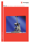
User’s manual
Copyrights
© 2004-2004, Thermopatch bv, Almere, the Netherlands. No part of this publication
may be reproduced by any means without the prior written permission of
Thermopatch bv, the Netherlands.
Thermopatch and the Thermopatch logo, Thermoseal and Thermocrest are
registered trademarks of Thermopatch.
2
NL-19 English Version 1.1 - 2004
Preface
Dear user,
Welcome to the growing group of Thermopatch users. The product you have
purchased has been carefully designed and manufactured to ensure that you, the
user, will gain the maximum benefit.
All Thermopatch products are specifically designed to ensure ease of use with
particular attention to safety requirements.
Should you discover any fault or damage upon receipt of this product, you should
immediately contact your local Thermopatch establishment.
3
NL-19 English Version 1.1 - 2004
EC - STATEMENT OF CONFORMITY
As manufacturer the company
Thermopatch bv
Draaibrugweg 14-16
1332 AD ALMERE - NETHERLANDS
confirms that the heat seal machine
NL-19
meets the requirements as stated in the EC directives for machine safety- and health
rules and is in accordance with the following requirements:
BS EN 292-1:1991
BS EN 292-2:1991
BS EN 60204-1:1991
BS EN 60529:1992
BS EN 418:1992
BS EN 1050:1997
E 55011:1998
EN 50081-1:1992
EN 50082-2:1995
BS 5304:1998
THERMOPATCH B.V.
4
NL-19 English Version 1.1 - 2004
Contents
1.
EC - STATEMENT OF CONFORMITY
4
Introduction
6
1.1
1.2
1.3
1.4
1.5
1.6
2.
Installation
2.1
2.2
2.3
2.4
3.
6
7
7
8
8
9
10
Transport instructions
Installing the machine
Electrical Requirements
Adjusting the pressure
10
10
10
11
How to operate the NL-19
12
3.1
3.2
3.3
3.4
3.5
3.6
3.7
3.8
4.
What did you receive?
Illustration of the NL-19
Specifications of the NL-19
Safety
Safety tips
Conditions for guarantee and product liability
Starting with the NL-19
Working with Heat Seal Materials
Material fusing
Stopping the machine
Pressing pad assembly
Shutting down
Fault diagnosis
Hints, tips and trouble shooting
Maintenance and settings
4.1
4.2
4.3
12
12
13
13
13
14
14
14
16
Daily maintenance
Periodic maintenance
Cleaning
16
16
16
5.
Drawings and diagrams
17
6.
Design Change
18
7.
Guarantee
19
Appendix A.
General Layout
20
Appendix B.
Control Unit
21
Appendix C.
Exploded Diagram & Parts List
22
Appendix D.
Electrical Diagram
23
Appendix E.
Controller – Electrical Diagram
24
5
NL-19 English Version 1.1 - 2004
1. Introduction
The NL-19 is a manually operated heat press for printing caps and similar small
items. It features a simple robust mechanism and electronic control of operating
temperature and dwell time, for accuracy and ease of operation.
The work area of the NL-19 is 15 x 9 cms (6 x 3.6 ins) .
The NL-19 is produced in two versions, nominally 240 Volt AC for the European
market and nominally 110 Volt AC for the American market.
1.1 What did you receive?
The NL-19 has been shrink wrapped, placed in a box, and held in place with foam.
The following articles should have been delivered:
♦
♦
♦
NL-19 complete with mains cable and plug
NL-19 Users’ Handbook
Any extra items ordered
If there is any damage or any article is missing, please contact your supplier
immediately.
6
NL-19 English Version 1.1 - 2004
1.2 Illustration of the NL-19
NL-19
1.3 Specifications of the NL-19
The NL-19 is a manually operated heat press for printing caps and similar small
items.
Specification European machine
Power consumption
Power supply
Compressed air supply
Compressed air consumption
Working temperature
Machine height open
Machine height closed
Machine width
Machine depth
Net weight
Press pad dimensions
Fuses
A-weighted noise level
500 Watt
240 Volts AC
7 bar max
60 litres/min
70-235°C
80 cms
43 cms
28 cms
52 cms
14,5 kg
15 x 9 cms
3.5A
<70dB(A)
7
NL-19 English Version 1.1 - 2004
Specification USA machine
Power consumption
Power supply
Working temperature
Machine height open
Machine height closed
Machine width
Machine depth
Net weight
Press pad dimensions
Fuses
A-weighted noise level
500 Watts
110 Volts AC
160-455°F
31 ins
17 ins
11 ins
21 ins
32 lbs
6 x 3.6 ins
7A
<70dB(A)
1.4 Safety
The Thermopatch NL-19 has been equipped with various safety features to ensure
operator safety.
a
Thermal cut-out
A thermal cut-out on the heating element shuts off the power to the element if the
temperature exceeds 235°C ± 15°C (455°F ± 27°F).
b
Time/temperature controller
The time/temperature controller has a built in facility giving error messages in the
event of faults with the element heating and control system.
1.5 Safety tips
Our customer service department has its own service engineers and, if required,
maintenance is available. This contract ensures prompt service in the event of
machine failure together with additional periodic inspections.
The Thermopatch NL-19 meets the European Legislation standard. Under normal
conditions accidents are rare. However listed below are some practical points to
ensure your safety.
1.
Always switch off the current (and pull plug out of the socket) when
undertaking maintenance work or when cleaning the machine.
2.
Ensure that there is sufficient space around the machine. Cables and
connections must not get jammed. Although the heat radiation of the press is
low, there should be enough space for cooling down.
3.
Avoid contact with the press element.
4.
Do not remove the base board or controller unless qualified to do so - touching
internal parts is dangerous and may cause shock hazard. All electrical
connections inside covers are live. Never operate the press with any covers
and/or guards removed.
5.
Protect the mains cable - damage to the mains cable may cause fire or shock
hazard. When unplugging, hold by the plug only and remove carefully. Take
care that the mains cable does not come into contact with the heat plate (or
moving parts of the mechanism) during operation of the machine.
6.
WARNING – THIS APPARATUS MUST BE EARTHED
7.
CAUTION – The machine gets hot whilst operating. Take care not to touch any
suyrfaces that are labelled “Caution, this plate is HOT”.
8
NL-19 English Version 1.1 - 2004
♦
Operating ambient temperature range - the operating ambient temperature range is
32 °F – 104 °F, (0 - 35°C) and humidity of 20 - 80%. This heat press is fitted with
a thermal cut out to ensure that it cannot operate above 235° ± 15°C (455 ± 27 °F).
♦
Machine fuses - type: ultra rapid (FF) fuses 1¼” 250 Vac max. 3.15 amps. (110 Vac
max. 7 amps).
1.6 Conditions for guarantee and product liability
Thermopatch guarantees correct working of the machine and its components for
twelve months, excluding the cover on the upper plate, the resilient pad of the lower
platen and the thermostat. The guarantee period of the temperature sensor and
heating element is only six months.
9
NL-19 English Version 1.1 - 2004
2. Installation
2.1 Transport instructions
The machine comes to you in a box. If you have to replace the machine at a later
time, it is recommended to pack it in a similar way in the same box. Please let the
press first cool down and lower the handle to the locked position.
2.2 Installing the machine
Take the Thermoseal NL-19 out of the box and put the machine on a worktable near
an earthed socket. Ensure that there is sufficient free space around the machine. Also
ensure that there are no items near the machine, which are sensitive to heat
radiation.
2.3 Electrical Requirements
The Thermoseal NL-19 should be connected to the mains supply (nominally 240V
AC electricity grid (220V or 110V alternating current). Use the machine's power
cable to provide current. The NL-19 is an earthed machine. Ensure that the supply
rating on the machine specification plate corresponds with your local supply and
that the correct plug is fitted.
Mains lead
The wires in this mains lead are coloured in accordance with the following code:
Green and Yellow:..................................................................................................Earth
Blue:.................................................................................................................... Neutral
Brown:...................................................................................................................... Live
As the colours of the wires in the mains lead of this apparatus may not correspond
with the coloured markings identifying the terminals in your plug, proceed as
follows:
♦
The wire coloured green and yellow must be connected to the terminal in the plug
which is marked by the letter E, or by the safety earth symbol coloured green, or
green and yellow.
♦
The wire coloured blue must be connected to the terminal which is marked with the
letter N, or coloured black.
♦
The wire coloured brown must be connected to the terminal which is marked with
the letter L, or coloured red.
♦
NOTE - Replacement of the mains cable must be done by a competent service
engineer.
♦
Heating element - The heating element fitted to this press is rated at 500 Watts.
Never connect to any outlet or power supply having a different voltage/frequency
from that on the machine data plate.
10
NL-19 English Version 1.1 - 2004
2.4 Adjusting the pressure
This press is fitted with a pressure adjusting unit, which enables the heat plate
assembly to be raised or lowered by use of a pressure adjustment knob located on
the top of the machine:
1.
To increase pressure or to use thinner materials turn knob clockwise.
2.
To decrease pressure or to raise the heat plate assembly to enable thicker
materials to be used, turn the adjustment knob anticlockwise.
NOTE - Do not adjust the pressure when the machine is clamped shut
CAUTION - Never increase the pressure to the extent of requiring undue force to
lower the toggle/heat plate assembly into the lock position, as this will place
excessive stress on the press frame, resulting in permanent damage to the press.
11
NL-19 English Version 1.1 - 2004
3. How to operate the NL-19
3.1 Starting with the NL-19
1
Starting
Plug into your supply outlet and switch supply on.
Please ensure the mains plug is easily accessible to the operator so that in the event
of a fault the machine can be unplugged.
2
On/off
Turn on the NL-19; the on/off switch is to the right of the controller. Set the
machine controls as necessary. See instructions for adjusting the pressure, and the
operation of the time temperature unit.
3.2 Working with Heat Seal Materials
1
Transfer paper
Ascertain from the supplier that the transfer paper and/or the suppliers of the
material, that the material to be used is suitable and has been prepared for transfer
printing.
2
Heat and time setting
Obtain from the supplier of the transfer paper the recommended temperature, time
and pressure settings for the material to be worked on. Approximate settings are
usually within the following:
Heat setting .................................................................... 180°C-200°C (350°F-400 °F)
Time dwell setting ................................................................................... 10-30 seconds
3
Operating the machine
Wait until the set temperature has been reached, signalled by the temperature on the
controller display reaching the required figure. Spread the material to be printed on
the worktable, removing all wrinkles. Place the label on the desired location and
lower the press head.
Start the sequence by pulling the button to unlock the handle from its vertical
position. This will activate the microswitch which starts the timer. When the set
time has elapsed, the buzer sounds. The handle is then unlocked and returned to the
vertical position. The head may then be swung aside for unloading and loading.
4
Labels, emblems and transfers
Confirm that the fabric does not have a finish or contain impurities. If necessary,
wash the fabric or put the part where the label will be positioned under the press for
a few seconds.
Use the following press times:
a
Label tapes
Poly/cotton and 100% polyester................................................................... 12 seconds
b
Emblems
Thermocrest, Topline ................................................................................... 12 seconds
Embroidered ................................................................................................. 20 seconds
12
NL-19 English Version 1.1 - 2004
c
Transfers
Truflex .......................................................................................................... 12 seconds
Thermomark (transfers on paper)................................................................... 5 seconds
Attention ! Some modern fabrics like terylene and various types of nylon cannot
withstand the press temperature of 204 °C. If you cannot be sure of the result, use a
sample of the same fabric, if possible, to see the result.
5
Removing heat seal material
Because Thermopatch materials must be wash resistant to all industrial washing
processes, it is not easy to remove heat seal material. You can act as follows:
3.
Put the garments with the label to be removed under the press for about 7
seconds. The glue layer will return to its liquid state.
4.
Leave the garment on the plate and remove the label, if necessary by means of a
pair of blunt scissors or tweezers.
5.
Please take care, the press plate is hot!
6.
Repeat this procedure if you cannot remove the label from the garment.
3.3 Material fusing
When the press is to be used for the fusing of susible interlining/heat bonding etc.,
ascertain from the supplier of the material to be used, the correct settings for time
and temperature for the process.
Heat setting ........................................................................ 120 – 170 C (250F – 340 F)
Time dwell setting ..................................................................................5 – 30 seconds
The method of operation for fusing is the same as for transfer printing.
During the fusing operation it will be found to be advantageous to lay a piece of
PTFE cover material (the same size as the table), over the article being fused. This
will act as an anti-stick barrier to prevent strike through of any surplus adhesive fron
the fusible materials adhering to the heat plate of the press.
Note:
It not advisible that this PTFE cover material be used when the press is being used
for transfer printing.
3.4 Stopping the machine
The machine can be stopped at any time by using the “EMERGENCY STOP”
button on the top of the press. This will automatically lower the worktable.
3.5 Pressing pad assembly
The pressing pad normally supplied with this machine is silicone rubber.
Alternatively a pad of foam with a “Nomex” cover may be supplied to special order.
The pressing pad must be maintained in good condition at all times and replaced
when showing signs of wear. A worn pressing pad will always affect the quality of
printing/fusing. Do not insert items into the machine which would tend to cut the
pressing pad, i.e. buttons, pins, press studs or zips.
13
NL-19 English Version 1.1 - 2004
Important note:
The pressing pad supplied with the machine is of the correct thickness. Using a
thicker pad may invalidate your warranty.
3.6 Shutting down
To shut down the machine, turn off the green illuminated rocker switch to the right
side of the controller. The handle should be in the up position.
3.7 Fault diagnosis
This machine had a built in fault diagnosis. The display may show the following:
1
Heat fault
If the element of the heat press, or the thermal cut-out go open circuit, after
approximately 20 minutes the display will show “Heat fault”. If this display is seen,
contact your machine supplier immediately.
2
Probe fault
If the probe goes open circuit, the display will show “Probe Fault” immediately.
Contact your machine supplier as soon as possible.
3
“CAL” Fault
If “CAL” appears in the controller display the controller will need to be
recalibrated. Switch off the machine and contact your supplier for an instruction
sheet.
CAUTION - In all fault conditions, swich off the power to the machine and unplug
the machine from the electrical supply before contacting your machine supplier.
3.8 Hints, tips and trouble shooting
Transfer printing
1.
Extra care should always be taken to ensure that transfer paper is placed print
down onto the article as mistakes will result in the heat plate becoming soiled
with ink and spoiling following work.
2.
When transfer printing, it may be found advantageous to cover the press pad
with paper to prevent strike-through of surplus ink, particularly when printing
thin material as surplus print on the pressing pad cover can also strike back on
the following work.
Transfer paper/motifs fail to print out correctly
CHECK:
1.
Heat and time dwell settings are correct
2.
Article having transfer applied is locked in contact between pressing pad and
heat plate
3.
Pressing pad is in good condition, is flat and making complete contact over the
whole area of the heat plate. See Pressing Pad details.
Ghosting (=double image) of Transfer Prints
CHECK:
1.
Material being used has been correctly heat set for transfer printing
2.
Material being used does not shrink during printing process, i.e. measure
material before and after printing
14
NL-19 English Version 1.1 - 2004
3.
Transfer paper does not move after printing process upon lift off of the heat
plate
4.
If possible, use adhesive coated paper, particularly to overcome fabric shrinkage
5.
By pre-shrinking of material in press before transfer printing
Inferior press results
Insufficient adhesion of the glue layer
1. Press time too short. Increase the time in steps of 2 seconds and try again.
2.
Temperature too low. Check with Thermolabels and increase the temperature, if
necessary.
3.
Press pad of the lower plate is worn-out. Install a new pad.
4.
The coating of the press element is impure or worn-out. Clean with a damp
cloth and replace it, if necessary. When replacing the , it is very important that
adhesive residue is removed from the heating element. To do this it is necessary
to heat up the machine, scrape off the glue remains by using a blunt pair of
scissors or a blunt filling-knife. Try to minimise the scratching. After this is
done, degrease the heating element and apply the selfadhesive .
Glue layer and/or transfer ink runs
1. Press time too long. Decrease the time in steps of 2 seconds and try again.
2.
Temperature too high. Check with Thermolabels and decrease the temperature,
if necessary.
Machine failures
Press does not warm up, indicator does not light up
1. The machine is not connected to the electricity grid. Put the plug of the power
cable in an earthed socket and switch the machine on.
2.
The machine is not connected. Set the switch at the back of the machine to the
correct position.
Press does not warm up
1. The sensor is defective. Please contact Thermopatch.
2.
The safety thermostat has been activated. Please contact our service department.
3.
The heating element is defective. Please contact our service department.
The press time cannot be correctly set
The electronics are defective. Please contact our service department.
There is no signal at the end of the press time
1. The timer is defective. Replace the timer with a new one.
2.
The electronics are defective. Please contact our service department.
15
NL-19 English Version 1.1 - 2004
4. Maintenance and settings
4.1 Daily maintenance
For good press results it is important to keep the press surfaces clean. Therefore,
clean the coating of the upper plate with a clean, dry cloth. Do not touch the heating
element!
Also clean the rubber of the press shoe daily with a dry cloth. Do not use solvents or
other chemical substances to remove impurities. Do not let buttons, zips, etc. come
between the plates. In this way, the silicone rubber will remain intact for a long
time.
4.2 Periodic maintenance
Put a few drops of oil on the various pivot pins and the pressure adjusting screw
every three months.
The lower press pad should be replaced regularly.
4.3 Cleaning
Clean the outside of the machine regularly with a clean, moist cloth. This may
conveniently be carried out before starting when the machine is cool. First unplug
the machine.
16
NL-19 English Version 1.1 - 2004
5. Drawings and diagrams
In Appendices A, B, C, D and E you find successively:
Appendix A:
General Layout
Appendix B
Control unit – Operation
Appendix C
Exploded diagram and parts list
Appendix D
Electric diagram
Appendix E
Controller – Electrical Diagram
17
NL-19 English Version 1.1 - 2004
6. Design Change
With the policy of constant improvement and/or modification to meet changing
conditions, the right is reserved to change the design and/or specifications at any
time without prior notification, and therefore specifications may vary and not be in
accordance with this manual.
18
NL-19 English Version 1.1 - 2004
7. Guarantee
This press is guaranteed to be free from defects in material and workmanship
(excluding pressing pad assembly) for a period of 12 months from the date of
supply.
Should in our opinion any part of this press be defective in materials or
workmanship, it will be replaced or repaired free of charge, provided that the press
has been installed and operated in the correct manner and not subjected to misuse.
(This is excluding any travelling and/or carriage costs which will be charged at our
discretion.)
A charge will be made for any costs incurred if a reported fault on the press is found
to be due to incorrect installation, operation and/or incorrect materials being used. It
is the responsibility of the press user to ensure the suitability of the materials
operating through the press.
In order for this guarantee to be effective, no return of machine or parts may be
made without prior factory authorisation.
The manufacturer shall not be liable for any injury, loss or damage, direct or
consequential, arising out of the use or the inability to use the product.
19
NL-19 English Version 1.1 - 2004
Appendix A.
General Layout
Drawing 5.1: General Layout
20
NL-19 English Version 1.1 - 2004
Appendix B.
Control Unit
Operation of Control Unit, Setting Time and Temperature
(The head must always be in the up position before the controller is set.)
Drawing 5.2: Control Unit
21
NL-19 English Version 1.1 - 2004
Appendix C.
Exploded Diagram & Parts List
Drawing 5.3: Exploded Diagram & Parts List
22
NL-19 English Version 1.1 - 2004
Appendix D.
Electrical Diagram
Drawing 5.4: Electrical Diagram
23
NL-19 English Version 1.1 - 2004
Appendix E.
Controller – Electrical Diagram
Drawing 5.5: Controller – Electrical Diagram
24
NL-19 English Version 1.1 - 2004