1
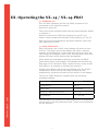
thermopatch.com NL-14 / NL-14-PRO User Manual Sep 2011 ENG Copyrights © 2011, Thermopatch bv, Almere, The Netherlands. No part of this publication may be reproduced by any means without the prior written permission of Thermopatch bv, The Netherlands. thermopatch.com Thermopatch and the Thermopatch logo, Thermoseal and Thermocrest are registered trademarks of Thermopatch. 2 Preface Congratulations and welcome to the ever growing number of Thermopatch users. You have acquired a machine which has been manufactured by Thermopatch with the greatest possible care. We are confident that you will be enjoying the use of this machine for a long time. Please take note of the contents of this manual to familiarize yourself with the workings and safety aspects of the machine. This manual was written for the benefit of all users and technicians who install and maintain the machine. thermopatch.com You will find information on operating, safety and maintenance as well as spare parts and supplies. 3 Table of Contents thermopatch.com Preface3 EC-Declaration of Conformity 5 I.Introduction 6 1.1 WHAT DID YOU RECEIVE? 6 1.2 YOUR SUPPLIER 6 1.3 SPECIFICATIONS OF THE THERMOSEAL NL-14 (PRO) 6 1.4 SAFETY 7 1.5 CONDITIONS OF WARRANTY AND PRODUCT LIABILITY 7 II.Installation 8 2.1 INSTRUCTION FOR HANDLING 8 2.2 INSTALLING AND CONNECTING THE NL-14 (PRO) 8 2.3 ASSEMBLY 8 III. Operating the NL-14 / NL-14-PRO 9 3.1 STARTING UP 9 3.2 FUNCTIONALITY 9 3.3 SAFETY 10 3.4 DISPLAY 10 3.5 TEMPERATURE SETTINGS 11 3.6 TEMPERATURE CHECKS 11 3.7 SETTING AND ADJUSTING THE PRESSURE 11 3.8 TIME SETTINGS 12 3.9 READING THE COUNTERS 12 IV.Maintenance 13 4.1 GENERAL 13 4.2 REPLACING THE FUSES 14 V. Possible faults 15 VI.Supplies 16 6.1 MOST COMMONLY USED PARTS 16 VII.Drawings, parts and schematics 17 4 EC-Declaration of Conformity We, Thermopatch B.V. Draaibrugweg 14 1332 Almere The Netherlands Herewith declare, on our own responsibility, that the machinery: Thermopatch Thermoseal NL-14 and NL-14-PRO, which this declaration refers to, is in accordance with the conditions of the following Directive(s): 2006/42/EG 2004/108/EG (Machinery directive) (EMC directive) The Netherlands, Almere, 01-01-2011 thermopatch.com Jan Bausch, Director 5 I. Introduction 1.1 What did you receive? The Thermoseal NL-14 (PRO) has been packed in a cardboard box. The following items are included: • Thermoseal NL-14 (PRO) heatsealmachine • Water condenser and pressure regulator • (PRO version) Foot pedal • Power cord • CD with manual • CE declaration of conformity If one or more of above are missing, please contact your Thermopatch supplier. 1.2 Your supplier Please look at our website, www.thermopatch.com to find your supplier. E-mail: [email protected] 1.3 Specifications of the Thermoseal NL-14 (PRO) The pneumatic machine NL-14 (PRO) is practical and universally applicable. It can be used to apply patches, textile emblems, heat seal transfers, in short all Thermopatch materials suited for marking and mending to textiles and technical fibres. The NL-14 machine is operated by a bi-manual control and the set temperature, time and pressure are presented upon its display. The NL-14 (PRO) is to be operated with the fitted foot pedal. thermopatch.com The Thermoseal NL-14 (PRO) has been manufactured in accordance with the European guideline for Machines, 2006/42/EC and the EMC guideline 2004/108/EC. This is declared with a general declaration added to this manual and uniquely serial number based to this machine. 6 Specifications: Power consumption during start-up 1000 Watt/230 Volt Power consumption in stand-by mode 10 Watt/230 Volt Power supply 230 Volt Temperature adjustable to maximal 230°C Safety temperature set to maximal 270°C Height (open) 350 mm Height (closed) 245 mm Width 265 mm Depth (including connections) 520 mm Nett weight 20 kg Sealing pad, size 150 x 125 mm Fuses 2 x 6,3 A (slow) A-weighted noise level < 70 dB (A) Pre-pressure < 6 bar Sealing pressure 4-6 bar Safety settings (min/max) 3,8 / 6 bar Compressed air usage (per cycle, 5 bar) +/-1 litre Sealing times, adjustable from - to 1 – 60 seconds Attention! To obtain the required sealing pressure, the NL-14 (PRO) has to be connected to a compressor with a working pressure of at least 6 bars. The air has to be clean and dry. thermopatch.com 1.4 Safety At normal usage no problems are to be expected. Regardless that, we state underneath a few pointers which will limit existing risks to a minimum. • Unplug the machine from the wall socket whenever you are maintaining or cleaning the machine. • Make sure there is enough working space around the machine. Although the heat radiation of the press is very low, it is still necessary to have enough room for cooling down. Extensions and connections must not get snagged. • Avoid contact with the press arm and the heating element. • Pull the fabric tightly over the sealing pad. 1.5 Conditions of warranty and product liability Thermopatch points to its warranty and product liability conditions as laid down in our sales conditions. These can be obtained at your Thermopatch supplier. 7 II. Installation 2.1 Instruction for handling The NL-14 (PRO) has been packed in a cardboard box. If you need the relocate the machine at a later point, we advise you to pack the machine in a similar fashion. Let the machine cool down completely before packing and moving it. 2.2 Installing and connecting the NL-14 (PRO) Take the Thermoseal NL-14 (PRO) from its box and place it onto a stable worktop near an earthed wall socket. Connect the machine with the supplied power cord to the electrical current (230 Volt, alternating current). The NL-14 is earthed and provided with two fuses (6,3 Amps, slow). 2.3 Assembly To ensure a problem-free operating of your NL-14 (PRO), it is essential to work with dry, clean compressed air. The supplied pressure regulator with water condenser is only an added protection of the machine. The user has to make sure that the pressure on the machine does not exceed 6 Bars. Connect a 6 mm air tubing with the compressor or the local compressed air system and connect this subsequently to the water condenser / pressure regulator mounted on the NL-14 (PRO). thermopatch.com The NL-14-PRO is fitted with a foot pedal for its operation. Connect the foot pedal by inserting the connector into its slot, which is placed underneath power entry on the back of the machine. Fasten the securing ring after inserting the connector. 8 III. Operating the NL-14 / NL-14-PRO 3.1 Starting up You can start operating the NL-14 (PRO) as soon as it is connected to the electricity mains. Set the air pressure. Take note of the conditions and working instructions as stated in chapter 2. Switch on the NL-14 (PRO) by pressing the on/off (I-0) switch, which is placed on the back of the machine, to “on (I)”. Wait until the set temperature has been reached, which will take about one minute. 3.2 Functionality When activated, the control unit’s display will show an icon of a fox. The lower part of the display will show a version number of the firmware. In this case this will be fox V01.XX. This image will disappear after a few seconds after which the display will show which setting was last applied. When faults are detected at starting up the NL-14 (PRO), these will be shown in the display. The machine will not warm up. See page 17 for the fault codes; faults will have to be solved first before it is possible to operate the machine. Usually the machine will show in its display only the actual temperature. When the NL-14 (PRO) is ready for use, temperature, pressure and time will be shown in the display. thermopatch.com The NL-14 (PRO) has been supplied with the following standard settings: Sealing time 12 seconds Temperature 204 °C Power safe 30 minutes Minimal – Maximal pressure 3.8 - 6.0 Air pressure 4.0 - 6.0 bar The setting of the sealing time and temperature is dependant on the type of job and materials used. These can be adjusted by the operator. 9 3.3 Safety The NL-14 has been fitted with a bi-manual control. The two push-buttons are mounted on either side of the machine. Both need to be pressed simultaneously for about two seconds; otherwise the machine will not close. The NL-14 also has a safety feature that prevents mechanical pressure to be executed, when the press arm cannot close (to about 8 mm above the sealing pad). The NL-14-PRO has been fitted a foot pedal therefore the machine has an added orange pressure sensitive safety rack, which is mounted on the sealing head to prevent the machine from closing when it detects an obstruction. The sealing cycle can be interrupted at any time by pressing any switch on the display. At the end of the sealing cycle an acoustic signal will sound. A safety thermostat has been integrated into the heating element, which interrupts the heating circuit when the temperature runs too high. This switch will cut off the power at approximately 270 °C. After the machine is switched off and has cooled down to a normal working temperature, the machine is again ready to be operated. When the actual temperature falls 15 °C outside the set temperature, the NL-14 (PRO) cannot be operated. thermopatch.com 3.4 Display The display shows: The set temperature 204 °C The applied pressure 5 bar The set time 12 seconds Day counter 001 Machine is in operational mode Pad lock symbol is closed 10 By using the button “AUTO” the NL-14 (PRO) can be switched () into or out () of the operational mode. Only when set to operational mode (), adjustments to the settings can be made. 3.5 Temperature settings The standard factory setting is 204 °C. When switched to the stand-by mode, the heating element is switched off. Stand-by is activated when the machine is left unused for more than 30 minutes. The working temperature is adjustable from 20 °C – 230 °C. The temperature setting can be adjusted by removing the machine from the auto mode (). By pressing the icon for temperature this will appear in the display and can be adjusted by pressing the – or + keys. Do not touch any keys for about 3 seconds so the setting can be entered into the memory. 3.6 Temperature checks The temperature is shown continually in the display. If required, you can do additional checks of the actual temperature between the sealing platens. This can either be done by a laser gun or by using Thermolabels. Both can be obtained through your Thermopatch supplier. 3.7 Setting and adjusting the pressure The machine is set to a working pressure of 5 Bars. If required, the pressure can be adjusted by turning the knob of the pressure regulator after which the chosen pressure will be shown on the display. thermopatch.com The NL-14 (PRO) has a pressure guarding system. This is set to a maximum of 6 Bars and a minimum of 2,5 Bars. At too high or too low pressure, the machine cannot be operated and an alarm indicator will show on the display. The setting of the lower setting of the air pressure is done by pressing the icon pressure after which the lower setting appears on the display. This can be adjusted by pressing the – or + keys. When the lower pressure is set to 0 (zero), the pressure guarding system is switched off. The upper setting of the air pressure is done by pressing the icon pressure twice, after which the upper setting appears on the display. This can be adjusted by pressing the – or + keys. To adjust the closing and opening speed of the sealing arm can be adjusted by setting two throttle valves. To be able to do this, the left side of the cover has to be removed. 11 Attention! Remove the plug from the wall socket before removing any screws. The throttle valves are situated on the back of the machine; one is for adjusting the upward speed, the other for adjusting the downward speed. By careful turning, the required corrections can be done: • Before correcting, loosen the lock nut and fasten again after the correction is done. • By turning the knob of the respective throttle valve to the right, the press arm will open or close slower, by turning it to the left it will open or close faster. 3.8 Time settings The standard time setting of the NL-14 (PRO) is set to 12 seconds. For adjusting this, remove the machine from its auto mode (). By pressing the time icon, the set time will appear on the display. By pressing the + or – key, this setting can be adjusted. Do not touch any keys on the display so the set time can be stored into the memory. The sleep-time delay can be set by pressing the time icon twice, after which the delay time appears onto the display, in minutes. By pressing the + or – keys, adjustments can be made and the machine will switch itself off after inactivity during the set time. thermopatch.com By pressing one of the push-buttons on the side, the machine can be quickly switched on again. When the set temperature is reached the machine can be re-activated again by pressing both push-buttons. 3.9 Reading the counters By pressing the temperature icon and the + key simultaneously for 3 seconds, the total counter will appear on the display. By pressing – or + keys, the counter can be set to 0 (zero). By pressing the pressure icon and – key simultaneously, the machine counter will appear on the display. This counter cannot be reset. The day counter is reset automatically to 001 after the machine is switched off. 12 IV. Maintenance 4.1 General Ensure that the cycle of the machine is finished, before working on the machine. Depending on the planned job you wish to perform, respectively the power – and air supply can be disconnected. Mechanism: The air cylinder and other parts of the machine are maintenance free and the bearings are self lubricating. The condition is that the heat seal machine is supplied with clean and dry compressed air. The mounted water condenser and pressure regulator is an added safety feature. Arrange for your machine to be maintained by qualified staff or a maintenance service. Moisture and unclean air disrupt the self lubricating properties of the air cylinder. Ensure that the pre-pressure does not exceed 6 Bars. Temperature: The temperature of the heating plate can be tested regularly by using Thermolabels or a laser gun. Both can be obtained at your Thermopatch supplier. Teflon cover: The Teflon cover of the heating plate should always be clean to prevent labels or patches sticking to it or soiling the heat seal products. Clean the cover with a dry, clean cloth when the machine is still warm. Repeat this several times a day when using the machine intensively. thermopatch.com Damaged or soiled Teflon covers need to be replaced. These can be obtained at your Thermopatch supplier. Sealing pad: Clean the sealing pad while it is still warm. Use a clean, lint free cloth to clean it regularly. Do not heat seal on zippers, staples, buttons etc. to avoid damage by puncturing or tearing the sealing pad. Never use solvents to clean the sealing pad. Replacing the Teflon cover or Sealing pad: The Teflon cover or the Sealing pad should, depending on their condition, be replaced regularly. When performing the replacement, make sure the machine has cooled down sufficiently. Peel off the self-adhesive Teflon cover (like a used band-aid). Then carefully remove any glue residue that was left behind. Make sure that all residue is removed and the metal surface is clean, before placing the new cover, without bubbles. Teflon covers and sealing pads can be obtained at your Thermopatch supplier. 13 Water condenser and pressure regulator: The water condenser and pressure regulator needs to be emptied of collected water on a daily basis. This can be done by pushing the pin at the bottom of the filter. Cleaning: Apart from taking care of the outside of the machine, the inside needs cleaning periodically. Undo the screws of the back cover and remove the housing. Attention! Remove the plug from the wall socket before removing any screws. 4.2 Replacing the fuses Ensure that the machine is disconnected from the electrical power and is unplugged from the wall socket. Replace the fuses on the back of the machine at the power entry. Before re-connecting the power cable into the wall socket, make sure the net entry shows the right tension setting (230 V or 110 V). If the wrong setting is shown, remove the fuses and turn the fuse holder 180°. After replacing the fuses, the machine can be connected and switched on again. thermopatch.com Attention! Check that the right tension setting is visible, before switching on the machine again! 14 V. Possible faults Code Description 01 Temperature sensor or broken cable 02 Shortcut temperature sensor 03 Heating element broken of broken cable 04 Pressure setting too low 05 Pressure setting too high 06 Broken cable or safety switch activated thermopatch.com Fault Possible cause Solution Heating plate stays cold. Temperature sensor defect. Replace Heating plate stays cold. Temperature sensor defect. Replace Display shows too low pressure (alarm). Pressure too low. Set pressure to right setting. Display too high pressure (alarm). Pressure is too high. Set pressure to right setting. After the heating up phase, Pressure too low, possible the display shows too low snagging of the air supply. pressure (alarm) at sealing. Set pressure to right setting. Machine opens too soon. Check by pressing the control key. The set values are not correct. Check air supply. Place the textile in a better fashion. Machine will not close. 1. B i-manual control was not pushed in long enough. Check 2. Pressure too low or too high. Check Check 3. M achine has not reached the set temperature yet. Machine closes but will not seal. The press arm is pushed up by the sealing pad. The placed textile is too thick, the machine cannot lock. 15 Check settings; check if textile can be placed in a better fashion or for suitability. VI. Supplies 6.1 Most commonly used parts • Sealing pad with thin metal plate, self-adhesive 143 x 117 mm SPA109001 • Teflon cover, self-adhesive 143 x 117 mm SPA109002 • Fuses thermopatch.com 2 x 6,3 A (slow) SPA105009 16 thermopatch.com VII. Drawings, parts and schematics 17 1.1 1.2 1.3 1.12 1.13 1.6 1.4 1.14 thermopatch.com 1.5 1.9 1.7 1.8 1.10 1.11 18 thermopatch.com NO. DESCRIPTION QTY. ART. NR. 1.1 Side plate left 1 SPA14003 1.2 Side plate right 1 SPA14004 1.3 Bottom plate 1 SPA14007 1.4 Running block 2 SPA14008 1.5 Socket head screw M5 X 15 6 DIN 912 1.6 Socket head screw M5 X 20 4 DIN 912 1.7 Nut M6 4 DIN 934 1.8 Knurled ring 6 mm 4 DIN 6798A 1.9 Rubber foot 25 x 20 4 SPAPEN01-03 1.10 Knurled ring 5 mm 6 DIN 6798A 1.11 Nut M5 6 DIN934 1.12 Knurled screw M6 2 DIN653 1.13 Washer M6 2 DIN125A 1.14 Nut M6 2 DIN934 19 2.1 2.2 2.3 2.4 2.18 thermopatch.com 2.5 2.6 2.17 2.7 2.8 2.9 2.10 2.11 2.12 20 2.13 2.14 2.15 2.16 thermopatch.com NO. DESCRIPTION 2.1 Collar bearing 2.2 QTY. PAF 12090 P10 ART. NR. 8 SPAPEN 02-03 Linking piece 2 SPA14005 2.3 Linking Triangle left 1 SPA14010 2.4 Adjusting bolt 1 ISO 7379 2.5 Linking Triangle right 1 SPA10 10-015 2.6 Socket head screw 4 DIN 912 2.7 Cylinder mounting plate 1 SPA14009 2.8 Knee 1/4" X 4 mm 2 SMC 2.9 Round head screw M10 X 40 2 ISO7380 2.10 Bearing plate 2 SPA14010 2.11 Roller bearing 26 mm 2 6000-2RSR 2.12 Washer 10 mm 2 DIN 125A 2.13 Roller bearing 30 mm 2 62200-2RSR 2.14 Nylock nut M10 2 DIN 985 2.15 Air cylinder RT/57250/M/100 1 SPA14025 2.16 Fork eye QM/8040/32 1 SPA14025A 2.17 Socket head screw M6 X 20 4 DIN 912 2.18 Adjustment bolt M10, Shaft 30 1 ISO 7379 M10, Shaft 50 M5 X 16 21 3.1 3.2 3.3 thermopatch.com 3.4 3.5 3.6 22 thermopatch.com NO. DESCRIPTION QTY. ART. NR. 3.1 Sealing pad, silicone 1 SPA109001 3.2 Support plate 1 SPA14012 3.3 Support bushing 2 SPA14011 3.4 Press leaver 1 SPA14002 3.5 Knurled ring M6 2 DIN6798A 3.6 Socket head screw M6 x 15 4 DIN 912 23 4.2 4.3 4.4 4.7 thermopatch.com 4.1 4.8 4.6 24 4.5 thermopatch.com NO. DESCRIPTION QTY. ART. NR. 4.1 Assembly 3 Page 27 4.2 Shoulder bolt 4.3 Assembly 2 Page 29 4.4 Assembly 1 Page 31 4.5 Nylock Nut M10 2 DIN934 4.6 Knurled ring 10 mm. 2 DIN6798A 4.7 Plastic ring 12 mm. 2 DIN125-A 4.8 Adjusting ring 12 mm. 1 DIN705A/916 M10, Shaft 100 mm 25 2 ISO7379 5.2 5.1 5.3 5.4 5.5 5.6 5.18 5.7 5.19 5.20 5.21 5.8 5.9 thermopatch.com 5.10 5.11 5.17 5.16 5.15 5.14 5.13 5.12 26 Only for NL-14-PRO 5.25 5.26 5.27 thermopatch.com 5.28 NO 5.25 5.26 5.27 5.28 5.29 DESCRIPTION Pressure spring Safety rack Safety switch Safety arm D118 27 QTY 2 1 2 2 ART. NR. thermopatch.com NO. DESCRIPTION 5.1 Collar bearing 5.2 Bearing block 5.3 Socket head screw 5.4 Press arm 5.5 Nylock nut 5.6 Pressure spring 5.7 Nylock nut 5.8 Isolation plate 5.9 Knurled ring 5.10 QTY. PAF 12090 P10 ART. NR. 2 SPAPEN0203 2 SPA14013 4 DIN 912 1 SPA14001 2 DIN 985 2 AVF D180S 6 DIN 985 1 SPA101018A 6 DIN 6798A Element without connector 1 SPA 141019A 5.11 Thermostat 1 SPAPEN 03-02 5.12 Silicone Round 25 mm. 1 SPA14050 5.13 Countersunk screw M5 X 40 4 DIN 7991 5.14 Temperature sensor PT1600 1 SPAMA 03-04/4 5.15 Countersunk screw M5 X 60 2 DIN 7991 5.16 Sensor shield 1 SPA 100107B 5.17 Heater shield 1 SPA 100107C 5.18 Closing ring M6 2 DIN 125A 5.19 Socket head screw M3 X 12 1 DIN 912 5.20 Connector Ceramic 2 SPAPEN 03-04 5.21 Nut M3 1 DIN 985 5.25 Pressure spring D118 2 SPA14025 5.26 Safety rack 1 SPA14020 5.27 Safety switch 2 SPA14021 5.28 Safety arm 2 SPA14022 5.29 Plain bearing 2 SPA14023 M6 X 10 M5 M5 M5 ø7x5.5x6 mm 28 6.1 6.2 6.3 thermopatch.com 6.7 6.4 29 6.5 6.6 thermopatch.com NO. DESCRIPTION QTY. ART. NR. 6.1 Shoulder bolt M10, Shaft 100 1 ISO7379 6.2 Shoulder bolt M10, Shaft 70 1 ISO7379 6.3 Assembly 5 6.4 Assembly 4 6.5 Nut M10 2 DIN985 6.6 Washer 2 DIN125/1A 6.7 Adjusting ring 2 DIN705A/916 12 mm 30 7.2 7.1 7.3 7.4 7.5 7.6 7.7 7.8 7.9 thermopatch.com 7.10 7.11 7.12 7.13 7.14 31 NO. DESCRIPTION Round head screw 7.2 M5 X 15 ART. NR. 12 ISO 7380 Sealing arm cover 1 SPA14032 7.3 Main electronic board 1 SPA140408 7.4 Back cover 1 SPA14014 7.5 Water condenser and pressure regulator 1 SPA106009 7.6 Power entry 1 SPA105003 7.7 Bulkhead passage 1 SPA106021 7.8 Display 1 SPA14014 7.9 Display print 1 SPAMA0402 7.10 Push-button 2 SPA14055 7.11 Lower cover left side 1 SPA14030 7.12 Front finishing profile 1 SPA14034 7.13 Upper finishing profile 1 SPA14035 7.14 Lower cover right side 1 SPA114031 7.15 Cover plate 1 SPA14033 thermopatch.com 7.1 QTY. 32 A B C D BLUE EARTH MICRO SYSTEMS MARCONIWEG 2 ZEEWOLDE NETHERLANDS COMPANY: ADDRESS: CITY COUNTRY: 8 INITIAL 30-08-2011 NL14 WIRING.UTSCH NL-14 PROJECT: 30-08-2011 FILENAME: DATE: 240 C THERMOSTATE1 1 POWER ENTRY MODULE EARTH REV: 1 AC IN L 7 PE BROWN N MAINSWITCH PAGE: ENG: RS HEATER 1 2 OF: 6 1 PT1600 - + WHITE WHITE VALVE MAINFILTER 6 L1 BROWN F2 BROWN BLUE BLUE 230V FUSE 6.3 A F1 BLACK BLACK PRESSURE SENSOR 5 ORANGE RED BROWN BLACK TEMP. J6 PRESS MAINBOARD 4 Page 1 of 1 (30-Aug-2011) 1 2 3 4 CERAMIC CONNECTOR 1 WHITE 2 WHITE 10 11 8 J10 J3 J4 J5 RED BLACK OPTIONAL 9 7 J2 5 1 2 3 4 OPTIONAL 6 CERAMIC CONNECTOR BLUE N1 BROWN 4 NL14 Wiring.UTSCH - SHEET 5 12 13 7 14 15 16 17 8 J8 SAVETY RELAY 18 19 20 thermopatch.com 3 J9 3 J7 J11 21 22 33 24 23 BLACK BLACK BLACK BLACK BLACK BLACK BLACK EARTH FOOT PEDAL 2 3 SAVETY BLACK 2 PRESS SWITCHES SAVETY DISPLAY / KEYBOARD 2 1 1 A B C D 11.1 11.2 11.3 11.4 11.6 P 11.6 thermopatch.com 11.7 NO. DESCRIPTION 11.1 Air cylinder 11.2 QTY. RT/57250/M/100 ART. NR. 1 SPA14-025 Adjustment valve 2 SPA 106023 11.3 Air valve 2/5 1 SPA 106005 11.4 Pressure sensor 1 SPAMA 06-13 11.6 Water condenser 11.6 Pressure regulator 1 SPA 106008 11.7 Quick fitting 1 SPA 105015 34 thermopatch.com Thermopatch Corporate Headquarters Thermopatch European Headquarters Thermopatch Australia Pty Ltd Thermopatch Canada Inc Kannegiesser UK Ltd. USA The Netherlands Australia Canada United Kingdom T T T T T +1 315 446-8110 +31 36 549 11 11 +61 395325722 +1 519 748-5027 +44 1539 722122 F F F F F +1 315 445-8046 +31 36 532 03 98 +386 2 80 55 232 +1 519 748-1543 +44 1539 721000 [email protected] [email protected] [email protected] [email protected] [email protected]