1
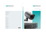
Day/Night DNR Color Camera CB-540WDR User Manual Thanks for purchasing our product. Before operating the unit, please read the instructions carefully and keep this manual for future reference. -1- Safety Warning 1. Read manual carefully before installing the unit. Please read this manual first for correct installation and operation. 2. Never install the camera on a ceiling that cannot hold its weight The product may fall down to cause damages. 3. Do not install the camera near electric or magnetic fields. Installed the camera away from TV, radio transmitter, magnet, electric motor, transformer, audio speakers because the magnetic fields generate from above devices will distort the video image. 4. Always stop using when the product emits smoke or abnormal heat 5. Never disassemble the camera nor put impurities in it Disassembly or impurities may result in trouble or fire. 6. Never face the camera toward the sun. Direct sunlight or severe ray may cause fatal damage to sensor and internal circuit. 7. Keep the power cord away from wet and never touch the power cord with wet hands. Touching the wet power cord with hands or touching the power cord with wet hands may result in electric shock. 8. Never install the camera in areas exposed to water, oil or gas. The water, oil or gas may result in failure, electric shock or file. 9. Cleaning Do not touch the surface of sensor by hand directly. Use a soft cloth to remove the dirt from the camera body. Use lens tissue or a cotton tipped applicator and ethanol to clean the sensor and the camera lens. 10. Do not operate the camera beyond the specified temperature, humidity or power source ratings. Use the camera at temperatures within -10°C ~ 50°C and humidity below 90%. The input power source is dual power DC12V/AC 24V. 11. Retain Instructions The safety and operating instructions should be retained for future reference. -2- 12. Heed Warnings All warnings on the unit and in the operating instructions should be adhered to. 13. Follow Instructions All operating and use instructions should be followed 14. Cleaning Unplug the unit from the outlet before cleaning. Do not use liquid cleaners or aerosol cleaners. Use a damp cloth for cleaning 15. Attachments Do not use attachment not recommended by the product manufacturer as they may cause hazards. 16. Water and Moisture Do not use this unit near water-for example, near a bath tub, wash bowl, kitchen sink, or laundry tub, in a wet basement, near a swimming pool, in an unprotected outdoor installation, or any area which is classified as a wet location. 17. Servicing Do not attempt to service this unit yourself as opening or removing covers may expose you to dangerous voltage or other hazards. Refer all servicing to qualified service personnel. 18. Power Cord Protection Power supply cords should be routed so that they are not likely to be walked on or pinched by items placed upon or against them, playing particular attention to cords and plugs, convenience receptacles, and the point where they exit from the appliance. 19. Object and Liquid Entry Never push objects of any kind into this unit through openings as they may touch dangerous voltage points or short-out parts that could result in a fire or electric shock, Never spill liquid of any kind on the unit. Notice: The information in this manual was current when published. The manufacturer reserves the right to revise and improve its products. All specifications are therefore subject to change without notice. . -3- 1. Product Overview .......................................................................................................... 6 1.1 Main Features: ......................................................................................................... 6 1.2 Content List.............................................................................................................. 6 1.3 Specifications ........................................................................................................... 7 2. Dimension and Functions .............................................................................................. 8 2.1 Dimension .................................................................................................................. 8 2.2 Description of functions .............................................................................................. 8 3.1 Setup Buttons: ............................................................................................................ 9 3.2 Display/Close the user setup menu screen .............................................................. 10 4. User Setup..................................................................................................................... 11 4.1 EXPOSURE ............................................................................................................. 11 4.1.1. LENS ............................................................................................................................ 11 4.1.2. BRIGHTNESS .............................................................................................................. 11 4.1.3. BACKLIGHT ................................................................................................................. 11 4.1.4. SHUTTER..................................................................................................................... 11 4.1.5. AGC .............................................................................................................................. 11 4.1.6. SENSE UP.................................................................................................................... 11 4.1.7. RETURN.......................................................................................................................12 4.2 WHITE BALANCE .................................................................................................... 12 4.3 DAY/NIGHT MODE .................................................................................................. 13 4.3.1. D/N MODE....................................................................................................................13 4.3.2. AUTO LEVEL................................................................................................................14 4.3.3. FILTER DLY ..................................................................................................................14 4.3.4. RETURN.......................................................................................................................14 4.4 MOTION DETECTION: ............................................................................................ 14 4.4.1. DETECT MODE............................................................................................................14 4.4.2. DETECT AREA.............................................................................................................14 4.4.3. SENSITIVITY................................................................................................................15 4.4.4. ALARM TIME ................................................................................................................15 4.4.5. RETURN.......................................................................................................................15 4.5 PRIVACY: ................................................................................................................. 15 4.6 OPTION:................................................................................................................... 17 4.6.1 TITLE .............................................................................................................................17 4.6.2. NEGA/POSI ..................................................................................................................18 4.6.3. SHARPNESS................................................................................................................18 4.6.4. MIRROR .......................................................................................................................18 4.6.5. ZOOM ...........................................................................................................................18 4.6.6. PAN/TILT ......................................................................................................................18 4.6.7. PHASE..........................................................................................................................19 4.6.8. RETURN.......................................................................................................................19 4.7 DISPLAY: ................................................................................................................. 19 4.7.1. TITLE ............................................................................................................................19 4.7.2. MOTION DET ...............................................................................................................19 -4- 4.7.3. CAMERA ID ..................................................................................................................19 4.7.4. RETURN.......................................................................................................................19 4.8 SYNC: ...................................................................................................................... 19 4.9 INITIAL: .................................................................................................................... 20 4.10 EXIT: ...................................................................................................................... 20 -5- 1. Product Overview CB-540WDR is designed with advanced new generation 16-bit DSP which has powerful processing capability to show over 540TVL horizontal resolution. Built-in DNR (Dynamic Noise Reduction) function, it performs clear & crisper image in low light and substantial disk-saving effect. In addition, designed with SENS-UP slow shutter technology, the starlight super-high sensitivity of 0.001 Lux is achieved. 1.1 Main Features: Excellent Super-high Resolution technology, 540 TV lines of horizontal resolution Advanced 16-bit Digital Signal Processor (DSP) delivers excellent picture quality and performance Day/Night function Built-in Mechanical IR Cut Filter Built-in DNR (Dynamic Noise Reduction) for noise reduction The super-high sensitivity of 0.001 Lux/F=1.0 is achieved by setting SENS-UP Shutter X32 OSD setting menu Support Motion Detection function Support Privacy function 1.2 Content List CB-540WDR Color Camera unit User’s manual -6- 1.3 Specifications TV System Image Sensor Total Pixels Effective Pixels Synchronization Frequency Resolution Dynamic Range Minimum Illumination S/N (Y signal) Video Output Iris Control Camera Title Day & Night Gain Control White Balance Back Light Compensation Electronic Shutter Menu Color Motion Detection Privacy Function Power Supply Power Consumption Operating Temperature/ Humidity Storage Temperature/ Humidity Dimensions Weight PAL NTSC 1/3 SONY Super HAD CCD 811 (H) x 508 (V) 795 (H) x 596 (V) 768 (H) x 494 (V) 752 (H) x 582 (V) Internal / Line-Lock H:15.734 KHz H:15.625 KHz V: 59.94Hz V: 50.00Hz 540TVL(Color Mode); 650TVL(B/W Mode) x80 normal camera Normal: 0.05Lux/F1.0 ; 0.001 Lux/F1.0 (Sens-up) More than 50dB (γ, Sharpness, AGC OFF) 1.0Vp-p/75Ω DC/ ELC OFF/ON AUTO/ DAY/ NIGHT/ EXT Selectable Low, Middle, High, OFF Selectable ATW/AWC/Manual LOW/MIDDLE/HIGH/OFF Selectable ESC (X128 ~1/60~1/120000 sec) OSD Control AUTO/ Day/ Night/ Ext Selectable (Daytime: Color, Night Time: B/W) ON/OFF ON/OFF (4 Programmable Zone per Screen) DC12V / AC24V 5.0W Max. -10°C~+50°C 90% RH Max. -20°C~+60°C / 20%~90% RH 63(W)×52(H)×121(L)mm 400g -7- 2. Dimension and Functions 2.1 Dimension 2.2 Description of functions 5 6 8 9 1 Lens mount This mount is used to install a CS-mount lens. CS-adaptor ring is required if use a C mount lens. 2 Camera mounting screw holes Screw hole for fixing camera. e Mount adaptor This adaptor can be attached to either the top or bottom of unit. f Auto iris lens connector (4-pin type) The lens connector supplies the auto-iris lens (not supplied) with DC control signal. PIN NO. 1 2 3 4 DC CONTROL CONTROL + DRIVE + DRIVE - 6 Setting Button SETUP button UP & DOWN button LEFT & RIGHT button -8- 7 VIDEO connector This is an output for connection to a video monitor, etc (75Ω). 8 MINI DIN connector 7 8 6 4 5 3 1 2 MINI DIN PIN PIN ASSIGNMENT PIN 1 RS485 + PIN 2 RS485 - PIN 3 GND PIN 4 MD LED OUT PIN 5 GND PIN 6 D/N LED CONT PIN 7 CDS IN PIN 8 12V OUT 9 Power Input Indicator Light When the camera is connected to a power supply, the indicator light will be on. Power input terminal Connect the power supply of 12Vdc / 24Vac. 3.1 Setup Buttons: To set items on the user setup menu, use the following buttons on the back panel. Up Button Set Button Left Button Down Button Right Button ① Up Button: This button is used to move the cursor upwards. Use this button to select the item wanted to set. ② Down Button: This button is used to move the cursor downwards. Use this button to select the item wanted to set. ③ Right Button: Use this button to select or adjust the parameters of the select item. The parameter changes each time as this button is pressed. If the item has its own setting sub-menu (sign +...), press this button to display the setting menu. -9- ④ Left Button: Use this button to select or adjust the parameters of the select item. The parameter changes each time as this button is pressed. ⑤ Set Button: This button is used to switch to the main menu. This is also a quick button to return the previous menu. 3.2 Display/Close the user setup menu screen SET button ENTER button The Cursor Buttons & the SET Button I. Press the SET button The menu screen will appear on the monitor as the block shown above. II. Using the cursor button Use the cursor button c or d to move the cursor up or down. Use the cursor button e or f to adjust the mode or parameter of settings. III. Switch to sub-menu screens When the item with sub-menu is selected, press the ENTER button to switch to the sub-menu for further settings. Please refer to the figure below. Main Menu Sub-Menu Note: For those select items with “+...” sign in the end, they have the sub-menu for further settings. IV.Return to previous page Select RETURN and press the ENTER button to return to previous page. V. Close the menu screen To close the menu screen, use the cursor button to select EXIT and press the ENTER button, or press the SET button. - 10 - 4. User Setup 4.1 EXPOSURE When the SETUP menu is displayed on the screen, please direct the arrow to point to “EXPOSURE” by using the UP/ DOWN buttons and press the ENTER button to enter the sub-menu. 4.1.1. LENS Depending on the type of the lens which is being used, select DC or ELC mode. 4.1.2. BRIGHTNESS The brightness of the screen can be adjusted from 0~60 by using cursor button e or f. 4.1.3. BACKLIGHT Even there is a massive backlight behind the object, bright images of the background and the object can still be obtained by using the BACKLIGHT function. Please use cursor button e or f to select LOW/MIDDLE/HIGH/OFF. 4.1.4. SHUTTER Select the shutter mode 1/60(NT), 1/100FL(NT), 1/250, 1/500, 1/1000, 1/2000, 1/4000, or 1/10000 by pressing the LEFT or RIGHT button. Please select “FL” mode when flickering occurs on the screen, because of an irregular balance between illumination and frequency. NTSC model: 1/100FL, PAL model: 1/120FL. Note: ¾ When “ELC” mode is ON, the SHUTTER function will be disabled to choose. 4.1.5. AGC Please use e or f button to select Low/Middle/High/OFF. The more the level of gain increases, the brighter the screen and the level of noise increases as well. 4.1.6. SENSE UP SENS UP is used to keep a brilliant, vivid screen image by automatically detecting changes in the level of light under low light level conditions. - 11 - Select the mode (OFF, x2, x4, x8, x16, x32) you would like to operate by pressing the LEFT or RIGHT button. Note: ¾ The maximum storage magnification in low light level movement situations can be adjusted by pressing the LEFT or RIGHT button. ¾ The screen becomes brighter when the magnification increases; yet the after image increases as well. ¾ Please be noted that spots and noise may appear if storage magnification increases when SENS-UP is operating. This is a normal phenomenon. 4.1.7. RETURN Press the RIGHT button to return to previous page or press SET button to close the menu directly. 4.2 WHITE BALANCE The screen color can be adjusted by using the WHITE BALANCE function. 1. Please direct the arrow to point to “WHITE BAL” on the SETUP menu by using the UP and DOWN buttons. 2. Please select the mode you would like to operate by pressing the LEFT or RIGHT button. Please select one of the 3 modes below: Ö ATW (Auto Tracking White Balance): This mode can be used within the color temperature range from 2,500°K to 9,000°K (eg, fluorescent light, outdoor, sodium vapor lamp or inside tunnels). Ö AWC (Auto White Balance Control): Press the PUSH AUTO button while the camera is directed at a piece of white paper to get the optimum state under the present illumination. If the environment and the light source are changed, you need to adjust the white balance again. Note: Under the following conditions, the WHITE BALANCE function may not operate well. ¾ When the ATW is on, the RED CONT/ BLUE CONT/ PUSH AUTO will be disabled. ¾ When the AWC is on, the RED CONT/ BLUE CONT will be disabled. However, the PUSH AUTO will be still available to adjust white balance. - 12 - Ö MANUAL: The manual adjustment mode enables a more precise adjustment. Please select ATW or AWC first. Then change to manual adjustment mode and press the SETUP button. Set the suitable color temperature, and increase or decrease the red and blue color values at the same time while checking the color changes of the object. WHITE BAL > WB MODE RED CONT BLUE CONT PUSH AUTO MANUAL 70 50 --- Note: Under the following conditions, the WHITE BALANCE function may not operate well. In such cases, please select the AWC mode. ¾ When the object’s surroundings have a high color temperature. ¾ When the object’s surroundings are dark. ¾ If the camera faces a fluorescent light directly or is installed in a place where the illumination changes constantly, the WHITE BALANCE function may become unstable. 4.3 DAY/NIGHT MODE The camera can be set in Color or B/W mode in the Day/Night function. Please direct the arrow to point to “D/N MODE” on the SETUP menu by using the UP and DOWN buttons. Then, press the Right button to enter the sub-menu. 4.3.1. D/N MODE Please select the mode you would like to operate by pressing the LEFT or RIGHT button. Ö AUTO: The camera will switch to B/W or Color mode automatically. Ö Day: Color mode. Ö Night: B/W mode. Ö EXT: The camera will switch to B/W or Color mode by external control. - 13 - Note: ¾ When the D/N MODE is set on “AUTO”, AUTO LEVEL/ FILTER DLY can be controlled by using the Left or Right buttons. 4.3.2. AUTO LEVEL There are 0~27 levels to select to be the switching point, and it changes by setting AGC. AGC OFF: NOT USE. AGC LOW: 0 to 3 can be selected. AGC MID: 0 to 11 can be selected. AGC HIGH: 0 to 27 can be selected. 4.3.3. FILTER DLY When the camera is equipped with a filter, the filter switching time can be set in this function from 4~10 sec. 4.3.4. RETURN Press the RIGHT button to return to previous page or press SET button to close the menu directly. 4.4 MOTION DETECTION: Please direct the arrow to point to “MOTION” by using the UP or DOWN button. Then, press the Right button to enter the sub-menu. 4.4.1. DETECT MODE Please press the LEFT or RIGHT button to select ON or OFF. 4.4.2. DETECT AREA Please use the UP or DOWN button to move between TOP, DOWN, LEFT and RIGHT for adjusting the size of the area to be detected. The black area is the potion of cursor; the gray area is undetected area; the transparent area is detected area. After the detected area has set, press the SET button to return the menu. - 14 - CURSOR UNDETECTED AREA DETECTED AREA 4.4.3. SENSITIVITY There are 8 levels (0~8) can be selected for the sensitivity of Motion Detection Function. 4.4.4. ALARM TIME The alarm time of Motion Detection can be set from 1 to 60 sec. 4.4.5. RETURN Press the RIGHT button to return to previous page or press SET button to close the menu directly. Note: ¾ After the Motion Detection is set completely, please go to the MOTIONDET under the DISPLAY in the MENU, and then select “MD” to appear at the upper-left corner on the screen. 4.5 PRIVACY: z z z z Please select the 1~4 areas you would like to block in AREA mode. Please select ON /OFF in the MASK mode for the chosen area. Please use the UP or DOWN button to move between TOP, DOWN, LEFT and RIGHT for adjusting the area to be masked. Please use the LEFT or RIGHT button to adjust the value for size of the area to be masked. - 15 - z AREA1 AREA2 AREA3 AREA4 Additionally, it is possible to change the position of the masked area. Please refer to the following example for detailed steps on moving AREA1 to center. 1. The original position of AREA1 was TOP: 34, DOWN: 66, LEFT: 20 and RIGHT: 66. AREA1 2. Increase DOWN scale value by 20. AREA1 position after change is: TOP: 34, DOWN: 86, LEFT: 20 and RIGHT: 66. AREA1 3. Increase TOP scale value by 20. AREA1 position after change is: TOP: 54, DOWN: 86, LEFT: 20 and RIGHT: 66. AREA1 - 16 - 4. Increase RIGHT scale value by 20. AREA1 position after change is: TOP: 34, DOWN: 66, LEFT: 20 and RIGHT: 86. AREA1 5. Increase LEFT scale value by 20. AREA1 position after change is: TOP: 34, DOWN: 66, LEFT: 40 and RIGHT: 86. AREA1 z z LEVEL: The brightness level of masked areas can be set from 0 to 15. RETURN: In order to save the changes and complete the setting, press the SETUP button. This allows you to return to the previous menu. 4.6 OPTION: 4.6.1 TITLE Input the camera ID, and it will be shown on the screen. Press the Right button to enter the sub-menu. ← A N a n 0 * → B O b o 1 / BS C P c p 2 + POS D Q d q 3 - E R e r 4 ~ F S f s 5 ! G T g t 6 # - 17 - H U h u 7 % I V i v 8 & END J W j w 9 ( K X k x : ) L Y l y ; “ M Z m Z . _ Maximum 10 letters can be used for the ID. ¾ Use UP and DOWN buttons to move the cursor to the letter to be chosen. ¾ Use UP, DOWN, LEFT and RIGHT buttons to select an ID. ¾ Use SETUP button to lock in the letters. Once a name has been selected, please choose a position where you would like to display the name. ¾ Move the cursor onto “POS” and press the SETUP button. ¾ The name will appear at the top left hand corner. ¾ Please use the 4 directional buttons to find the desired position to display the name. If you would like to cancel the ID input, please move the cursor to “BS”, and all the letters input will be deleted. Select “END” and press SETUP button to complete the ID input. Note: ¾ After the setting is completed, please go to the TITLE under the DISPLAY in the MENU and set the function ON to appear on the screen. 4.6.2. NEGA/POSI Please press the LEFT or RIGHT button to select NEGA or POSI mode. 4.6.3. SHARPNESS The contour of the video image becomes cleaner and more distinguishing as the level of SHARPNESS increases. If the level goes up extremely, it may affect the video image and cause noise. Please press Right and Left buttons to adjust the level. The available range of level is 0~15. 4.6.4. MIRROR Press the LEFT or RIGHT button to select the mode you would like. NORMAL: Normal image. MIRROR: Horizontal image inversion. VERTICAL: Vertical image inversion. ROTATE: Horizontal and Vertical image inversion. 4.6.5. ZOOM Use the LEFT or RIGHT button to select from 1~8. 4.6.6. PAN/TILT Press the LEFT or RIGHT button to set ON or OFF. When the setting is ON, the picture will be zoomed in. (Select RETURN and press the SET button to return to the menu.) Please use the UP, DOWN, LEFT, RIGHT buttons to adjust the area. If you want to close this function, please press the SET button to enter the MENU option and set the PAN/TILT OFF. - 18 - 4.6.7. PHASE When the SYNC. in the MENU is set on AUTO, the phase can be adjusted from 0~524(NTSC) or 0~624(PAL). Note: ¾ In LINE-LOCK mode, without a synchronous generator, it synchronizes the video signal between cameras. The Line-Lock synchronization is only used in the places of 60Hz (NTSC models) or 50Hz (PAL models). 4.6.8. RETURN Press the RIGHT button to return to previous page or press SET button to close the menu directly. 4.7 DISPLAY: 4.7.1. TITLE After the setting of TITLE under the OPTION menu is ready, set this function ON and the title will be displayed on the screen. 4.7.2. MOTION DET After the setting of DETECT MODE and DETECT AREA under the MOTION DETECTION menu is ready, set this function ON and “MD” will be displayed on the screen. 4.7.3. CAMERA ID This is an identification number for the camera. 4.7.4. RETURN Press the RIGHT button to return to previous page or press SET button to close the menu directly. 4.8 SYNC: There are two SYNCHRONIZATION modes: INTERNAL and LINE-LOCK. In LINE-LOCK mode, without a synchronous generator, it synchronizes the video signal between cameras. The Line-Lock synchronization is only used in the places of 60Hz (NTSC models) or 50Hz (PAL models). - 19 - 4.9 INITIAL: When users have set certain functions, “USE” will be shown in the INITIAL. If the users wish to return the default setting, please press the LEFT and RIGHT buttons at the same time, and the camera will be reset to the default setting. 4.10 EXIT: Save all the setting menus and exit. Note: ¾ If you quit the Menu without pressing EXIT, all the settings you previously did will NOT be saved. Fracarro Radioindustrie S.p.A. - Via Cazzaro n.3 - 31033 Castelfranco Veneto (TV) ITALIA Tel: +39 0423 7361 - Fax: +39 0423 736220 Società soggetta a direzione e coordinamento di CAMI S.r.l. - partita IVA 02399120266 Fracarro France S.A.S. - 14 bis rue du Ratrait - 92158 Suresnes Cedex FRANCE Tel: +33 1 47283419 - Fax: +33 1 47283421 Fracarro Iberica - Poligono Táctica, “Ciudad de los negocios” c/2A n°4 - 46980 Paterna - Valencia - ESPAÑA Tel. +34/961340104 - Fax +34/961340691 Fracarro (UK) - Ltd, Unit A, Ibex House, Keller Close, Kiln Farm, Milton Keynes MK11 3LL UK Tel: +44(0)1908 571571 - Fax: +44(0)1908 571570 Fracarro Tecnologia e Antenas de Televisao Lda - Rua Alexandre Herculano, n°1-1°B, Edifício Central Park 2795-242 Linda-a-Velha PORTUGAL Tel: + 351214156800 - Fax+ 351214156809 www.fracarro.com [email protected] - 20 -