1
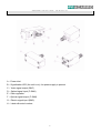
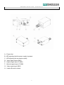
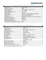
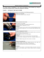
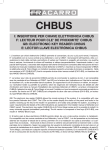
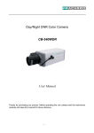
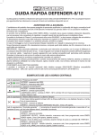
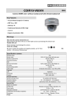
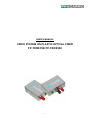
USER’S MANUAL
VIDEO SYSTEM ON PLASTIC OPTICAL FIBER
FP-TXRX150/ FP-TXRX300
1
REFERENCE FIGURES - FP-TXRX150
A – Power inlet
B – Signalization LED (the unit is on), the power supply is present
C – Video signal output (BNC)
D – Optical signal input (F-SMA)
E – Gain regulation
F – Optical signal output (F-SMA)
G – Electric signal input (BNC)
H – Label with serial number
2
REFERENCE FIGURES - FP-TXRX300
A – Power inlet
B –LED signaling that the power supply is present
C - LED signaling the connection quality
D – Video signal output (BNC)
E – Optical signal input (F-SMA)
F – Optical signal output (F-SMA)
G – Video signal input (BNC)
H – Label with serial number
3
THE ADVANTAGES OF THE PLASTIC OPTICAL FIBER
This Video System works with plastic optical fiber (POF). The use of the plastic fiber
guarantees the following:
1) the transmission of analog video signals up to 300 m away (FP-TXRX300) and up to 150
m away (FP-TXRX150);
2) easy and fast installation without specific tools;
3) complete immunity to electromagnetic disturbances and no electromagnetic emissions;
4) complete immunity to ground loops;
5) high resistance to weather conditions, dust, oils and mechanical stresses;
6) existing raceways containing electric cables can be used.
4
TECHNICAL SPECIFICATIONS - FP-TXRX150
Manufacturer
Degree of protection
Image standard
Transmitted band
Transmission distance (m)
Gain regulation
Power supply
Consumption (mA)
Weight (g)
Dimensions (mm)
Optical output connector
Electric input connector
Storage temperature (°C)
Operating temperature (°C)
Immune to electromagnetic interferences
Made in Italy
IP20
PAL / SECAM / NTSC (1 Vpp)
0 ~ 5.5 MHz
10 ~ 150
Manual
+12V CC stabilized (feeder not supplied)
80 max (Tx) / 50 max (Rx)
50 (Tx) e 70 max (Rx)
44.60x29.40x26.90 (Tx) / 65.7x27.5x25.8 (Rx)
F-SMA
BNC 75Ω
-30 ~ +70
-20 ~ +60
Yes
TECHNICAL SPECIFICATIONS - FP-TXRX300
Manufacturer
Degree of protection
Image standard
Transmitted band
Transmission distance (m)
Gain regulation
Total weight (g)
Consumption (mA)
Weight (g)
Power supply
Dimensions (mm)
Signalization LED
Made in Italy
IP20
PAL / SECAM / NTSC (1 Vpp)
0 ~ 6.0 MHz
120 ~ 300 *
Automatic (AGC)
183
80 max (Tx) / 200 max (Rx)
69 (Tx) / 114 (Rx)
+12VDC (feeder not supplied)
45x29x26 (Tx) / 66x45x26 (Rx)
On (PWR)
Signal presence (LINK)
F-SMA
BNC (75 Ω)
-30 ~ +80
-20 ~ +60
Yes
Optical output connector
Electric output connector
Storage temperature (°C)
Operating temperature (°C)
Immune to electromagnetic interferences
NOTES with repeater, FP-REP600 model up to 600 m
5
OPENING THE BOX
Carefully take the unit and the accessories out from the packaging box. Make sure that the box
contains all the components listed in the accessory list.
Carefully check the device and make sure that it was not broken or damaged during
transportation.
Do not throw away the box before having checked the unit carefully and made sure it works
properly.
LIST OF THE INCLUDED ACCESSORIES:
−
−
−
−
1 User’s manual
1 Transmitter
1 Receiver
1 BNC/BNC 75Ω cable
DESCRIPTION
The system converts and transmits, by plastic optical fiber (POF), the analog video signal
coming from any camera or video source.
The system is made up of the following:
a) a transmitting unit that can be interfaced with any analog camera;
b) a receiving unit to display the image onto a color TV or by means of an acquisition card
(optional) on a PC.
The color image in PAL/NTSC standard is acquired from the camera through the transmitting
unit and sent via plastic optical fiber to the receiver that can be connected to a color TV or a PC
with a frame grabber (not supplied).
FP-TXRX150 connection diagram
FP-TXRX300 connection diagram
FP-TXRX300 and FP-REP600 connection diagram
The use of the FP-REP600 model repeater allows you to reach and transmit up to 600 m
6
INSTALLATION OF THE DEVICE
The video system installation is very easy and requires a few minutes by using an
electrician's common tools. Follow the instructions carefully.
PHASE 1 – THE END OF THE PLASTIC FIBER
The ends of the cable must be carried out according to the following procedure:
1st Phase: Cut of the fiber
The cut can be carried out by any cutting tool
2nd Phase: Removal of the sheath
Remove about 1 cm of sheath
The optical cable sheath has a diameter of about 2.2 mm.
The optical cable has a diameter of 1.0 mm.
ATTENTION
The sheath removal can be carried out with a standard stripping tool that
has hole dimensions higher than 1.0 mm so that the optical cable will not be
damaged.
3rd Phase: Crimping the connector
Insert the FSMA connector on the previously stripped cable up to when the
optical cable comes out of about 2 mm.
Crimp the FSMA connector on the cable sheath.
ATTENTION
The FSMA connector cannot be crimped directly on the optical cable.
The FSMA connector crimping tool must have a hexagonal diameter of 3
mm.
If a FSMA – CRIMP crimping tool is used, use the 0.122 hole.
4th Phase: cleaning the fiber
To eliminate possible micro-lesions caused by the cut of the cable, use
1,000 abrasive paper possibly using the FP-CLEANTOOL.
Polish until the fiber does not jut out from the FP-CLEANTOOL.
ATTENTION
To optimize this process, we recommend making the figure 8 with the
connector on the abrasive paper so that the optical cable can be lapped
evenly.
7
PHASE 2: THE DEVICE INSTALLATION
The transmitter: (FP-TXRX150 o FP-TXRX300)
Connect the camera output to the transmitter module input
with the supplied BNC plug cable. The supplied cable can
be replaced by any 75Ω BNC cable (max. length 3 m).
Insert the plastic optical fiber (with the F-SMA connector at
one end) and fix it, screwing the connector onto the
transmitter.
Connect the 12V power supply; the connector polarity is
shown on the metal surface.
The transmitter will signal the correct lighting by means of
the proper LED.
The receiver:
Connect the receiver module output to the monitor/DVR input with a 75Ω BNC plug cable
(not supplied – max. length 3 m).
Insert the plastic optical fiber (with the F-SMA connector at one end) and fix it, screwing the
connector onto the receiver.
Connect the 12V power supply; the connector polarity is shown on the metal surface.
The receiver will signal the correct lighting by means of the proper LED.
FP-TXRX150
Manually adjust the gain (ADJ) with a screwdriver.
If the image displayed is too bright on the monitor,
decrease the receiver gain by turning it clockwise.
If image displayed is too dark on the monitor, increase
the receiver gain by turning it counterclockwise.
FP-TXRX300
The receiver provides an automatic regulation of the
gain and does not need regulation.
The LINK indicator shows the correct presence of the
video signal with the color green and its absence with
the color red.
8
OTHER ACCESSORIES
The range of Fracarro products includes the following accessories that are useful for installing
devices working with plastic optical fiber:
FSMA-ADAPTER
F-SMA metal connectors to crimp (box of 10 pieces)
PAPER-1000
KIT for working on the cable end
(Crimping tool, 1,000 abrasive paper, 10 F-SMA connectors, automatic puck
stripping tool, cutter)
FSMA-CRIMP
Crimping tool of F-SMA HEX 3.0 mm connectors
MANUFACTURER'S NOTES
In the presence of an electromagnetic field with a frequency between 1.4 GHz and 2 GHz and a
level higher or equal to 3V/m (according to the EN 61000-4-3 variant A1), the FP-TXRX300
device, during its normal operation, allows for the presence of slight video signal interferences
of the video signal. These interferences are shown as slightly marked horizontal lines over the
image, which is always perfectly visible.
9
TROUBLESHOOTING
FP-TXRX150:
1) You can’t see the image
a. double check the electric connections (LED PWR lit on TX and RX) and BNC cables
b. check that the transmitter emits a green light from the SMA receptacle
c. check that green light comes out from the fiber close to the receiver
d. adjust the gain regulator (E) (turn counterclockwise)
2) The image is very bright and/or instable
a. adjust the gain regulator (E) (turn clockwise)
b. check the fiber length (longer than 10 m)
3) The image has a poor quality
a. adjust the gain regulator (E) (turn counterclockwise)
b. check the length of the fiber (less than 150 m)
c. review the connectors by using abrasive paper and a puck
FP-TXRX300:
1) Passing from light/shade, the TV loses the image
a. disconnect the camera AGC
2) You can’t see the image
a. check that the device switches on correctly
b. check that the LINK indicator is green
b. check the length of the fiber (within the range of 120 m-300 m)
3) RED LINK LED/ poor quality of the image
a. check the length of the fiber (if less than 300 m, insert a repeater at the half of the
tract)
b. redo the connection
Fracarro Radioindustrie S.p.A. - Via Cazzaro n.3 - 31033 Castelfranco Veneto (TV) ITALIA Tel: +39 0423 7361 - Fax: +39 0423
736220
Company subjected to the management and coordination of CAMI S.r.l. – V.A.T. number 02399120266
Fracarro France S.A.S. – 7-14 rue du Fossé Blanc - 92230 Gennevilliers Cedex
FRANCE Tel: +33 1 47283400 - Fax: +33 1 47283421
Fracarro Iberica - Poligono Táctica, “Ciudad de los negocios” c/2A n°4 - 46980 Paterna - Valencia - ESPAÑA Tel.
+34/961340104 - Fax +34/961340691
Fracarro (UK) - Ltd, Unit A, Ibex House, Keller Close, Kiln Farm, Milton Keynes MK11 3LL UK Tel: +44(0)1908 571571 - Fax:
+44(0)1908 571570
Fracarro Tecnologia e Antenas de Televisao Lda - Rua Alexandre Herculano, n°1-1°B, Edifício Central Park 2795-242 Linda-aVelha PORTUGAL Tel: + 351214156800 - Fax+ 351214156809
www.fracarro.com [email protected]
FP-TXRX Rev. 0 07th Nov. 2008
10