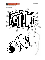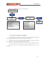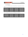
1
User Manual USER MANUAL 2002 Edition. Previstorm® is a registered trademark of DENA DESARROLLOS, S.L. © Copyright DENA DESARROLLOS, S.L. All rights reserved. DENA DESARROLLOS, S.L. C/ Duero, 5 08223-Terrassa Barcelona-Spain Tel: 93-7360305 Fax: 93-7360303 Mail: [email protected] Web: http://www.ingesco.com 1 User Manual Previstorm® User Manual Table of Contents 1. Presentation 2. Wariness 3. Components 4. Description 4.1 Equipment description 4.2 Diagram 5. Technical features 5.1 Introduction 5.2 MCE Sensor 5.3 Data Acquisition Box (MAD) 6. Installation 6.1. Equipment installation 6.2. Installation diagram 7. Principle of Operation 8. Configuration 8.1 System configuration 8.2 Using the menus to adjust parameters 8.3 Parameter adjustments diagram 8.4 Technical parameters 9. Errors 9.1 Alarm Device 9.2 Troubleshooting 2 User Manual 1. INTRODUCTION Thank you for acquiring our PREVISTORM® system, which has been developed from our experience in storm detection and prevention experience. Important. Please read this manual carefully before putting the system in service and do not hesitate in consulting us if there are any doubts. 2. Wariness SECURITY WARNING When any task related to the unit must be done, please observe the following precautions in order to avoid risk of fire and electric shock: G G G G G G G Do not damage the power cable or place heavy objects on the equipment. Treat the equipment with care. Avoid accidental jars or vibrations via imprudent manipulation. If it is suspected that the equipment has suffered any damage, disconnect it and request service immediately. Before moving the equipment, always disconnect it and unplug the power cable. If any abnormal noises, vibrations or odors are detected coming from the equipment, switch it off immediately and unplug the power cable. Request service immediately. In the event of cleaning the MAD ensure that it is disconnected from the electrical outlet. To avoid risk of electrical shock, do not touch the equipment with wet or moist hands. Never install the equipment near flammable substances such as diluting alcohol or any other type of volatile material. Operation precautions G G G G G G G G To avoid damage, never place the equipment on unstable or vibrating surfaces. Keep all liquids, such as drinks, away from the equipment. If any liquid accidentally enters the equipment, turn it off, unplug the power cable, and request service immediately. When installing the Data Acquisition Module (MAD), avoid atmospheric dust and high humidity. Do not place heavy objects on the equipment. Do not disconnect the power cable by jerking it brusquely. Electric Risk. This risk is null if the equipment is connected to a good ground. Do not touch the MCE while it is on (especially the helices). In case of fire do not attempt to put it out with water. 3 User Manual 3. COMPONENTS Verify that all the materials indicated below are included. • Data Acquisition Box MAD • Exterior MCE sensor • PREVISTORM® Management software • Cables and connectors • Manuals • Power Supply 24V power supply or 24V uninterruptible power supply 4 User Manual 4. Description 4.1 Description Previstorm® is composed of: G MCE (A) sensor or capture device with: (1) G Connector base (2) G Rotating plate . (18) G Screws to fasten to a 50 mm diameter mast. G Capture Cable (B) (3) G Connection plug G Data Acquisition Box, (MAD)(C). (4) G LCD Screen (5) G Screen illumination button (6) G Buzzer (7) G Programming keyboard (8) G Indicator lights for each alarm (8b) . G System error or failure Indicator light (9) G Connector G Box plate (D) (10) G Mounting holes (11) G Cover (12) G Connection terminals (13) G Start / Stop switch (14) G Power cable grommet (15) G Alarm signals grommet (16) G MCE device cable grommet (19) connector for PC-MAD communication G RS-232 5 User Manual 4.2 Diagram 10 6 5 19 4 16 15 7 14 8 13 8b D 12 11 17 C 1 3 B 2 18 A 6 User Manual 5. Technical characteristics 5.1. Introduction The "Field mill" utilized by the Previstorm® is the only system able to preventively detect lightning phenomena. It is not necessary for a lightning strike in order to detect some type of storm activity. Other capturing devices need lightning to strike in order to begin the detection process, being already too late to take proper action. Previstorm measures the electrostatic field representative of the electric storm activity which might provoke lightning strikes if the electrostatic field overcome a detailed value. The electrostatic field (kV/m) measures the difference of potential that there is between the cloud and the zero earth potential per length unit. A measure process exemple will be: 1) 2) 3) 4) 5) Electrostatic field in normal conditions is around 0.150 kV/m Storm starts Alarm 1 or distant storm: reports the beginning of a storm activity Alarm 2 or near storm, conveys the approximation or local formation of a storm Alarm 3 or active storm, warns of a strong probability of a lightning strike within the measured area. 6) After the alarm time defined, the alarms get automatically disactivated. Note: The alarms levels are defined by defect but they are adjustables. Please see chapter 8: Configuration. The warning time depends on the cloud’s features: Cloud’s movement speed Cloud’s creation speed Cloud’s dimensions When the storm detection system’s situation is not normal: ð height in front of the sea ð high structure in front of the earth ð antennes or structures proximity the electrostatic field is deformed and the measure it is affected by an important, constant and lineal coefficient factor. The Coefficient form corrects these situations. 7 User Manual 5.2. MCE Capture Device MCE Capture Device ± 100 kV/m 10 V/m -20 a + 50 ºC Dynamics Resolution Operating Temperature Integrated worm-up system Files (IP 54) EC Compliance 5.3 Data Acquisition Box – MAD Central MAD Device Power Consumption Operating Temperature Relays 24 V DC Min. 400mA / Max. 1A -10 a + 50 ºC 250 V /10 A (Clear Power) IP 33 Compliance CE 5.4. Standards The MCE and MAD have been submitted to differents tests to be in compliance with the following standards: Electromagnetic compability • • • • EN 50081-2 (94) EN 61000-3-2 (97)//A12 (97)//AI (99)// A2(99) EN 61000-3-3 (97) EN 61000-6-2 (00) Tropicalization B.T. Security • • KK DIN 50017 KFW DIN 50017 • EN 61010 • EN 60529 IP Protection 8 User Manual 6. Installation 6.1. Equipment Installation The equipment operates with continuous 24 V DC power. This be either an uninterruptible power supply with batteries, or by direct 24 V DC power supply. Install the MCE capture device or sensor outside where the horizontal plane is as clear from obstructions as possible (See annex). Attach the connection cable to the MCE passing it inside the mast, and connect it to the sensor. The mast and the MAD modules are to be grounded to earth. Connect the following terminals: G G G G In J1, the power cable (+ a 1, ground a 2, - a 3) In J2 alarm and error relay contacts: G Alarm 1 (1,2,3) G Alarm 2 (4,5,6) G Alarm (7,8,9) G Error (10,11,12) In J3, the MCE sensor cable (2 twisted pairs, flattened and stripped wire for ground). RS-232 connector for connecting with the PC. The connection diagram and contact placements are described below: Power Supply Output Relays MCE RS-232 9 User Manual The connection cable between the central unit and the MCE sensor follows the following diagram: MCE M A D The wall-fastening diagram: 180 mm 10 User Manual 6.2. Installation diagram • • The ground installation consists of a mast of 1,5m in height and 50 mm in diameter. This can be installed on a roof , laterally supported on facades, etc.. 11 User Manual 7. Principles of Operation The equipment operates completely automatically. Starting and stopping the equipment is done by way of switch 13. Stopping the equipment does not erase its configuration. The electrostatic field is permanently display on the screen. Screen illumination can be activated with button 5. The light will automatically turn off after 10 minutes. When the corrected field value surpasses any of the alarm levels, the corresponding alarm indicator light is activated and its rely is tripped. A message appears on the screen indicating the type of alarm activated. In the event of Previstorm® failure, the illuminated ERROR indicator lights, and the error relay is thrown. The buzzer incorporated in the device will activate along with any type of alarm. When an alarm occurs, it will remain active until: G G After Alarm level 1, 2, or 3, when the field level falls to levels below that of the corresponding alarm, a period above the “Alarm Finish Time” parameter. After an Error Alarm, when the error is resolved. The alarms can be manually deactivated, which has the effect of stopping the audio alarm warning, and switching the relays to their normal state. The alarm indicator light does not switch off when canceling the alarm. The indicator will remain active while the field measurement is superior to the corresponding alarm level. The alarm levels and times are changed with the configuration buttons. 12 User Manual To obtain the storm risk indication, 3 levels of alarms allow to control different warning levels: G ALARM 1 “distant storm”, reports the beginning of a storm activity. G ALARMA 2 “near storm”, conveys the approximation or local formation of a storm. G ALARMA 3 “active storm”, warns of a strong probability of a lightning strike within the measured area. The field measurement is corrected by a form coefficient to take the influences of the MCE sensor or capturing device location into account. This corrected field measurement is what is presented on the system screen, and which is used to compare with the alarm level values. Detection reliability is important; when there is no field activity there is 100% assurance that there is no storm risk. The relays associated with the alarms permit: G Activation of visual and audio alerts. ✓ G Inform a system which operates as central alarm control. ✓ G Activate systems such as electric generators. ✓ G Isolation of the installation to be protected. ✓ 13 User Manual 8. Configuration Before starting the equipment, carefully check that all connections are correct. 8.1 System Configuration The Equipment is started with the ON / OFF button, modify the form coefficient to obtain the normalized value according to the placement topology. This parameter is found in the MAC menu. Modify the values of the Level Alarms according to the function mode desired. It is recommended to adjust the Alarm Levels in the following order: ALARM 1 < ALARM 2 < ALARM 3 Adjust the times according to the desired affect. In the case of it is recommended to define the value at 10 minutes. This parameter is adjustable in the menu. Levels recommended, already configurated at the equipment are: Alarm 1 Alarm 2 Alarm 3 2 kV/m 4 kV/m 8 kV/m 8.2. Using the menus to adjust parameters There are two distinct menus, one for the MCE capture device and another for the MAD console. To access the adjustments dialog, press the menu key and the adjustments for the MCE capture device will appear. Pressing the menu key again will bring up the MAD controls and pressing the menu key again will return it to the work screen. Use the left and right arrows to advance through the various menu options until the parameter desired is reached. To modify the menu, press the ok key and increase or decrease the value with the up and down arrows, once adjusted press the ok key. To exit the menu dialog press the menu again until the electric field reader screen is reached 14 User Manual Below is a summary graphic of the available menus Regular working MENU Sensor setting MCE 1 Alarm 1 threshold 2 Alarm 2 threshold 3 Alarm 3 thresold 4 Form factor 5 Alarm timer 6 Serial number * 7 Operating days * 8 Software version * Module setting MAD MENU 1 Buzzer acknowled 2 Alarms acknowled 3 LCD contrast 4 Buzzer volume 5 Buzzer timer 6 Menus language 7 Serial number * 8 Software version * MENU Regular working 8.3. Parameter adjustments diagram Programming the equipment is done using the incorporated keyboard. Each valid action realized with the keys is signaled with a tone from the buzzer. When in a menu, if no key is press within 5 minutes, the system will exit the menu and return to its normal state (displaying the field value). Parameter configuration operations can be made while the equipment is running. Not all parameters are user adjustable, parameters indicated with an * are not accessible. 15 User Manual 8.4. Parameters The user modifiable parameters of the MCE sensor or capture device are listed below: Parameters MCE Alarm Level 1 Alarm Level 2 Alarm Level 3 Form coefficient Alarm duration Default Value 2 kV/m 4 kV/m 6 kV/m 1 10 minutes Minimum 0 0 0 0 0 Maximum 100 100 100 10 60 The user modifiable parameters of the central MAD unit are listed below: Parameters CAF LCD Contrast Buzzer Cancel Alarm Cancel Buzzer Volume Default Value 5 NO NO 5 Minimum 1 Maximum 9 1 9 16 User Manual 9. Errors 9.1. Alarm Device The equipment continually performs auto-tests. If an internal error is detected, the illuminated ERROR indicator lights to inform the user. In some cases, the error is accompanied with a messaged on the screen with describes the type of error in more detail. These errors can be: G G G Anormal velocity: The rotating of the sensor or capture device is blocked or turns at an incorrect velocity. Broken Link: The connection has been lost or the cable between the MCE sensor and the central MAD unit has been disconnected. Extreme Temperature: The internal temperature of the MCE sensor is low. 9.2. Troubleshooting In case of an error, verify the following point: G G G G G G Read the type of error on the screen. Check for the presence of power to the central unit. Check equipment fuses. Check that the rotating plate of the MCE sensor is not blocked. Check the integrity of the cable between the MCE sensor and the central unit, and that it is properly connected. If the error is remaning, please consult with your porveyor 17