1
USER'S MANUAL
FX3U-64DP-M PROFIBUS-DP Master Block
Safety Precautions
(Read these precautions before use.)
Before installation, operation, maintenance or inspection of this product, thoroughly read through and
understand this manual and all of the associated manuals. Also, take care to handle the module properly and
safely.
This manual classifies the safety precautions into two categories:
and
.
Indicates that incorrect handling may cause hazardous conditions, resulting in
death or severe injury.
Indicates that incorrect handling may cause hazardous conditions, resulting in
medium or slight personal injury or physical damage.
Depending on the circumstances, procedures indicated by
may also cause severe injury. It is
important to follow all precautions for personal safety.
Store this manual in a safe place so that it can be taken out and read whenever necessary. Always forward it
to the end user.
1. DESIGN PRECAUTIONS
Reference
Page
• Make sure to have the following safety circuits outside of the PLC to ensure safe system operation
even during external power supply problems or PLC failure.
Otherwise, malfunctions may cause serious accidents.
1) An emergency stop circuit, a protection circuit, an interlock circuit for opposite movements,
such as normal and reverse rotations, and an interlock circuit for preventing damage to the
machine at the upper and lower positioning limits should be configured on the outside of the
PLC.
2) Note that when the PLC CPU detects an error, such as a watchdog timer error, during selfdiagnosis, all outputs are turned off. Also, when an error that cannot be detected by the PLC
CPU occurs in an input/output control block, output control may be disabled.
Design external circuits and mechanisms to ensure safe operations of the machine in such a
case.
3) Note that when some sort of error occurs in a relay, triac or transistor of the output unit/block,
output may be kept on or off.
For output signals that may lead to serious accidents, design external circuits and
mechanisms to ensure safe operations of the machine.
23
26
Reference
Page
• Make sure to observe the precautions below to prevent damages to the system due to the
abnormal data writing by noise to the PLC:
1) Do not bundle the control line together with or lay it close to the main circuit or power line. As
a guideline, lay the control line at least 100mm (3.94") or more away from the main circuit or
power line. Noise may cause malfunctions.
2) Ground the shield wire with the PLC. Do not ground together with high voltage lines.
• Install module so that excessive force will not be applied to peripheral device connectors. Failure
to do so may result in wire damage/breakage or PLC failure.
(i)
23
26
31
Safety Precautions
(Read these precautions before use.)
2. INSTALLATION PRECAUTIONS
Reference
Page
• Make sure to cut off all phases of the power supply externally before attempting installation or
wiring work.
Failure to do so may cause electric shock.
26
Reference
Page
• Use the product within the generic environment specifications described in the PLC main unit
manual (Hardware Edition).
Never use the product in areas with dust, oily smoke, conductive dusts, corrosive gas (salt air, Cl2,
H2S, SO2, or NO2), flammable gas, vibration or impacts, or exposed to high temperature,
condensation, or wind and rain.
If the product is used in such conditions, electric shock, fire, malfunction, deterioration or damage
may occur.
• Install the product securely using a DIN rail or mounting screws.
• Install the product on a flat surface.
If the mounting surface is rough, undue force will be applied to the PC board, thereby causing
nonconformities.
• When drilling screw holes or wiring, make sure cutting or wire debris does not enter the ventilation
slits.
Failure to do so may cause fire, equipment failures or malfunctions.
• Be sure to remove the dust proof sheet from the PLC's ventilation port when the installation work is
completed.
Failure to do so may cause fire, equipment failures, and malfunctions.
• Connect the extension and communication cables securely to their designated connectors.
Unsecured connection may cause malfunctions.
• Do not touch the conductive parts of the product directly to avoid failure or malfunctions.
27
3. WIRING PRECAUTIONS
Reference
Page
• Cut off all phases of the power supply externally before installation or wiring work in order to avoid
damage to the product or electric shock.
31
Reference
Page
• When drilling screw holes or wiring, make sure cutting or wire debris does not enter the ventilation
slits.
Failure to do so may cause fire, equipment failures or malfunctions.
(ii)
31
Safety Precautions
(Read these precautions before use.)
4. STARTUP AND MAINTENANCE PRECAUTIONS
Reference
Page
• Do not touch any terminal while the PLC’s power is on.
Doing so may cause electric shock or malfunctions.
• Before cleaning or retightening terminals, externally cut off all phases of the power supply.
Failure to do so may cause electric shock.
• Before modifying or disrupting the program in operation or running the PLC, carefully read through
this manual and the associated manuals and ensure the safety of the operation.
An operation error may damage the machinery or cause accidents.
23
97
100
116
Reference
Page
• Do not disassemble or modify the unit.
Doing so may cause fire, equipment failures, or malfunctions.
* For repair, contact your local Mitsubishi Electric distributor.
• Do not drop the product and exert strong impact. Doing so may cause damage.
• Turn off the power to the PLC before attaching or detaching the peripheral devices.
Failure to do so may cause equipment failures or malfunctions.
23
97
100
116
5. DISPOSAL PRECAUTIONS
Reference
Page
• Please contact a certified electronic waste disposal company for the environmentally safe
recycling and disposal of your device.
24
6. TRANSPORTATION PRECAUTIONS
Reference
Page
• The PLC is a precision instrument. During transportation, avoid impacts. After transportation, verify
the operations of the products.
(iii)
24
(iv)
FX3U-64DP-M PROFIBUS-DP Master Block
User’s Manual
FX3U-64DP-M PROFIBUS-DP Master Block
User’s Manual
Manual number
JY997D19201
Manual revision
B
Date
4/2006
Foreword
This manual contains text, diagrams and explanations which will guide the reader in the correct installation,
safe use and operation of the FX3U-64DP-M and should be read and understood before attempting to install
or use the unit.
Store this manual in a safe place so that you can take it out and read it whenever necessary. Always forward
it to the end user.
This manual confers no industrial property rights or any rights of any other kind, nor does it confer any patent
licenses. Mitsubishi Electric Corporation cannot be held responsible for any problems involving industrial property
rights which may occur as a result of using the contents noted in this manual.
© 2005 MITSUBISHI ELECTRIC CORPORATION
1
FX3U-64DP-M PROFIBUS-DP Master Block
User’s Manual
Outline Precautions
• This manual provides information for the use of the FX3U-64DP-M. The manual has been written to be
used by trained and competent personnel. The definition of such a person or persons is as follows;
a) Any engineer who is responsible for the planning, design and construction of automatic equipment
using the product associated with this manual should be of a competent nature, trained and qualified
to the local and national standards required to fulfill that role. These engineers should be fully aware of
all aspects of safety with regards to automated equipment.
b) Any commissioning or service engineer must be of a competent nature, trained and qualified to the
local and national standards required to fulfill that job. These engineers should also be trained in the
use and maintenance of the completed product. This includes being completely familiar with all
associated documentation for the said product. All maintenance should be carried out in accordance
with established safety practices.
c) All operators of the completed equipment should be trained to use that product in a safe and
coordinated manner in compliance to established safety practices. The operators should also be
familiar with documentation which is connected with the actual operation of the completed equipment.
Note: the term 'completed equipment' refers to a third party constructed device which contains or uses
the product associated with this manual
• This product has been manufactured as a general-purpose part for general industries, and has not been
designed or manufactured to be incorporated in a device or system used in purposes related to human life.
• Before using the product for special purposes such as nuclear power, electric power, aerospace, medicine
or passenger movement vehicles, consult with Mitsubishi Electric.
• This product has been manufactured under strict quality control. However when installing the product
where major accidents or losses could occur if the product fails, install appropriate backup or failsafe
functions in the system.
• When combining this product with other products, please confirm the standard and the code, or regulations
with which the user should follow. Moreover, please confirm the compatibility of this product to the system,
machine, and apparatus with which the user is using.
• If in doubt at any stage during the installation of the product, always consult a professional electrical
engineer who is qualified and trained to the local and national standards. If in doubt about the operation or
use, please consult the nearest Mitsubishi Electric distributor.
• Since the examples indicated by this manual, technical bulletin, catalog, etc. are used as a reference,
please use it after confirming the function and safety of the equipment and system. Mitsubishi Electric will
accept no responsibility for actual use of the product based on these illustrative examples.
• This manual content, specification etc. may be changed without a notice for improvement.
• The information in this manual has been carefully checked and is believed to be accurate; however, if you
have noticed a doubtful point, a doubtful error, etc., please contact the nearest Mitsubishi Electric
distributor.
Registration
• Microsoft® and Windows® are either registered trademarks or trademarks of Microsoft Corporation in the
United States and/or other countries.
• The company and product names described in this manual are the registered trademarks or trademarks of
their respective companies.
2
FX3U-64DP-M PROFIBUS-DP Master Block
User’s Manual
Table of Contents
SAFETY PRECAUTIONS ..................................................................................................... i
Applicable Standards ............................................................................................................... 7
Location and Usage of Manual ................................................................................................ 8
Associated Manuals.................................................................................................................. 9
Generic Terms and Abbreviations......................................................................................... 10
Reading of the Manual ............................................................................................................ 11
1. Introduction
12
1.1 Features of the FX3U-64DP-M ....................................................................................................... 12
1.2 External Dimensions and Each Part Name.................................................................................... 13
1.2.1 External Dimensions and Each Part Name .................................................................................... 13
1.2.2 Pin Configuration of PROFIBUS-DP Connector............................................................................. 14
1.3 System Configuration..................................................................................................................... 14
1.3.1 Applicable PROFIBUS-DP Network ............................................................................................... 14
1.3.2 Applicable PLC ............................................................................................................................... 17
1.4 Communication Time ..................................................................................................................... 18
1.4.1 Communication Time...................................................................................................................... 18
1.4.2 PROFIBUS (Bus) Cycle Time......................................................................................................... 19
1.5 System Start-up Procedure............................................................................................................ 22
2. Specifications
23
2.1 General Specifications ................................................................................................................... 24
2.2 Power Supply Specifications.......................................................................................................... 24
2.3 Performance Specifications ........................................................................................................... 25
3. Installation
26
3.1 Arrangements................................................................................................................................. 28
3.2 Mounting ........................................................................................................................................ 29
3.2.1 Direct Mounting .............................................................................................................................. 29
3.2.2 DIN Rail Mounting .......................................................................................................................... 30
4. Wiring
31
4.1 Applicable Cable and Connector.................................................................................................... 31
4.2 PROFIBUS-DP Wiring ................................................................................................................... 32
4.3 Grounding ...................................................................................................................................... 32
4.4 Bus Terminator............................................................................................................................... 32
3
FX3U-64DP-M PROFIBUS-DP Master Block
User’s Manual
5. Mode, Data Communication, Global Control
33
5.1 Cyclic I/O Data Communication ..................................................................................................... 33
5.1.1 Mode in Cyclic I/O Data Communication........................................................................................ 33
5.1.2 Normal Service Mode (Mode 0)...................................................................................................... 34
5.1.3 Extended Service Mode (Mode 3) .................................................................................................. 35
5.2 Acyclic I/O Data Communication.................................................................................................... 36
5.3 Diagnostic Information ................................................................................................................... 37
5.3.1 Slave Diagnostic............................................................................................................................. 37
5.3.2 Alarm Message............................................................................................................................... 38
5.4 Global Control ................................................................................................................................ 38
5.4.1 SYNC and UNSYNC Global Control .............................................................................................. 39
5.4.2 FREEZE and UNFREEZE Global Control ...................................................................................... 40
6. Allocation of Buffer Memories (BFMs)
41
6.1 Buffer Memories (BFM) Lists ......................................................................................................... 41
6.2 Communication Status [BFM #0] ................................................................................................... 46
6.3 Communication Control Flags [BFM #1] ........................................................................................ 47
6.4 Consistency Handling Error Flags [BFM #2] .................................................................................. 48
6.5 PROFIBUS Error Flags [BFM #3] .................................................................................................. 49
6.6 Dwell Time Flag / Whole Config Data Exchange Flag [BFM #4].................................................... 49
6.7 Module READY Signal [BFM #5] ................................................................................................... 50
6.8 PROFIBUS (Bus) Cycle Time [BFM #6 to #8]................................................................................ 50
6.9 Acyclic Slave Communication Deactivation Message Flags [BFM #18 to #21] ............................. 50
6.10 PROFIBUS Module ID (PNO ID) [BFM #26] ................................................................................ 51
6.11 Master Reset [BFM #27] .............................................................................................................. 51
6.12 Setting Error Flags [BFM #28]...................................................................................................... 51
6.13 Master Error Status [BFM #29] .................................................................................................... 52
6.13.1 Master Reset Status Flag [BFM #29 Bit 0] ................................................................................... 52
6.13.2 Master Hardware Error [BFM #29 Bit 1] ....................................................................................... 52
6.13.3 Slave Parameter Error [BFM #29 Bit 3] ........................................................................................ 52
6.13.4 Setting Error Flag [BFM #29 Bit 4]................................................................................................ 53
6.13.5 Consistency Error Flag [BFM #29 Bit 5] ....................................................................................... 53
6.13.6 Acyclic Communication Deactivation Message Flag [BFM #29 Bit 7] .......................................... 53
6.13.7 PROFIBUS Error Flag [BFM #29 Bit 8] ........................................................................................ 53
6.13.8 Slave Diagnosis Available Flag [BFM #29 Bit 9] .......................................................................... 53
6.13.9 Alarm Message Available Flag [BFM #29 Bit 10] ......................................................................... 53
6.13.10 No Configuration Available Flag [BFM #29 Bit 11] ..................................................................... 53
6.13.11 Mode Change Not Possible Flag [BFM #29 Bit 12] .................................................................... 54
6.13.12 Diagnosis FIFO Full [BFM #29 Bit 13] ........................................................................................ 54
6.13.13 Data Exchange Error [BFM #29 Bit 14] ...................................................................................... 54
6.13.14 Slave Change Address Error [BFM #29 Bit 15] .......................................................................... 54
6.14 Module ID Code [BFM #30].......................................................................................................... 54
6.15 PROFIBUS Master Address [BFM #31] ....................................................................................... 54
6.16 PROFIBUS Transmission Speed [BFM #32] ............................................................................... 55
6.17 Clear Control Flag [BFM #33] ...................................................................................................... 55
6.18 PROFIBUS Error Mask Flag [BFM #34]....................................................................................... 56
6.19 Number of Allocated Slaves [BFM #38] ....................................................................................... 56
6.20 Operation Service Mode [BFM #39]............................................................................................. 56
6.21 Data Swap Activate Flag [BFM #73 to #76] ................................................................................. 57
6.22 Change Slave FDL Address [BFM #81 to #83] ............................................................................ 57
6.23 Cyclic Input Data .......................................................................................................................... 58
6.23.1 Cyclic Input Data Consistency Activate/Deactivate Flags [BFM #84 to #87]................................ 59
6.23.2 Cyclic Input Data Request Flags [BFM #100 to #163].................................................................. 59
6.23.3 Cyclic Input Data Area in Normal Service Mode [BFM #350 to #1373]........................................ 60
6.23.4 Cyclic Input Data Area in Extended Service Mode [BFM #350 to #1373] .................................... 61
4
FX3U-64DP-M PROFIBUS-DP Master Block
User’s Manual
6.24 Cyclic Output Data ....................................................................................................................... 62
6.24.1 Cyclic Output Data Consistency Activate/Deactivate Flags [BFM #92 to #95]............................. 63
6.24.2 Cyclic Output Data Send Flags [BFM #225 to #288].................................................................... 63
6.24.3 Cyclic Output Data Area in Normal Service Mode [BFM #2350 to #3373] ................................... 64
6.24.4 Cyclic Output Data Area in Extended Service Mode [BFM #2350 to #3373] ............................... 65
6.25 Acyclic Input Data ........................................................................................................................ 66
6.25.1 Acyclic Input Data Request Flags [BFM #4500 to #4503] ............................................................ 67
6.25.2 Acyclic Input Data Area [BFM #4520 to #5015]............................................................................ 67
6.26 Acyclic Output Data...................................................................................................................... 68
6.26.1 Acyclic Output Data Send Flags [BFM #4510 to #4513] .............................................................. 69
6.26.2 Acyclic Output Data Area [BFM #5760 to #6255]......................................................................... 69
6.27 Master/Slave Internal Slave Parameter Error Flags [BFM #7000 to #7003] ................................ 70
6.28 Master/Slave Internal Slave Parameter Error Data [BFM #7008 to #7071] ................................. 70
6.29 Slave Diagnostic Information ....................................................................................................... 71
6.29.1 Slave Diagnostic Status Flags [BFM #7200 to #7203] ................................................................. 72
6.29.2 Slave Diagnostic Request [BFM #7208]....................................................................................... 72
6.29.3 Request Slave Number [BFM #7209]........................................................................................... 72
6.29.4 Slave Diagnostic Information Data [BFM #7210 to #7335]........................................................... 73
6.30 Diagnostic Information FIFO ........................................................................................................ 77
6.30.1 FIFO Diagnostic Request [BFM #7336]........................................................................................ 78
6.30.2 Internal FIFO Counter [BFM #7337] ............................................................................................. 78
6.30.3 Diagnostic FIFO Data Area [BFM #7338 to #7463]...................................................................... 78
6.31 Slave Diagnostic Status Data [BFM #7464 to #7591] .................................................................. 79
6.32 Alarm Message ............................................................................................................................ 80
6.32.1 Automatical Acknowledge Setting [BFM #8784 to #8787]............................................................ 82
6.32.2 Alarm Acknowledge Status [BFM #8792 to #8795] ...................................................................... 82
6.32.3 Alarm Message Status [BFM #8800 to #8803]............................................................................. 83
6.32.4 Alarm Message Counter [BFM #8808 to #8871] .......................................................................... 83
6.32.5 Alarm Message Request [BFM #8933]......................................................................................... 83
6.32.6 Request Slave Number [BFM #8934]........................................................................................... 83
6.32.7 Alarm Message [BFM #8935 to #8969] ........................................................................................ 84
6.32.8 Alarm ACK Request [BFM #8970]................................................................................................ 85
6.32.9 Slave Number [BFM #8971] ......................................................................................................... 85
6.33 Address Information Area [BFM #9140 to #9267]........................................................................ 85
6.34 Global Control .............................................................................................................................. 87
6.34.1 Global Control Area [BFM #9390] ................................................................................................ 87
6.34.2 SYNC and UNSYNC Global Control ............................................................................................ 88
6.34.3 FREEZE and UNFREEZE Global Control .................................................................................... 89
6.35 Information Dwell Time Setting [BFM #9394]............................................................................... 90
6.36 Cyclic Slave Status Area [BFM #9399 to #9402] ......................................................................... 91
6.37 Acyclic Slave Status Area [BFM #9407 to #9410]........................................................................ 91
6.38 Cyclic Input Data Start Address Area [BFM #9426 to #9489] ...................................................... 92
6.39 Cyclic Output Data Start Address Area [BFM #9551 to #9614] ................................................... 93
6.40 Number of Configured Slaves [BFM #9676] ................................................................................ 94
6.41 Slave Number, Slave FDL Address, Slave PNO ID [BFM #9677 to #9868] ................................ 94
6.42 PROFIBUS Scan Function........................................................................................................... 94
6.42.1 Get DP-Slave List Request [BFM #10052] ................................................................................... 95
6.42.2 Configuration Difference Status [BFM #10053 to #10060] ........................................................... 95
6.42.3 Scan Slave FDL Address [BFM #10061]...................................................................................... 96
6.42.4 Number of Detected Slave [BFM #10062].................................................................................... 96
6.42.5 Detected Slave Lists [BFM #10063 to #10443] ............................................................................ 96
7. Setting Parameters and Configuration [GX Configurator-DP]
97
7.1 Master Parameter .......................................................................................................................... 98
7.2 Bus Parameter ............................................................................................................................... 99
7.3 Network Configuration.................................................................................................................... 99
5
FX3U-64DP-M PROFIBUS-DP Master Block
User’s Manual
8. Example Program
100
8.1 Example Program 1 ..................................................................................................................... 100
8.1.1 System Configuration ................................................................................................................... 100
8.1.2 Contents of Operation .................................................................................................................. 100
8.1.3 Setting Network Configuration and Parameter for Example Program .......................................... 101
8.1.4 Example Program by GX Developer ........................................................................................... 105
8.1.5 Example Program by GX IEC Developer (Ver. 7.00 or later) ....................................................... 108
8.2 Example Programs to Read Alarm Message from PROFIBUS-DPV1 Slave (Alarm Model) ....... 112
8.2.1 An Example Program by GX Developer ....................................................................................... 112
8.2.2 An Example Program by GX IEC Developer (Ver. 7.00 or later)................................................. 113
8.3 Initializing the Network ................................................................................................................. 115
9. Diagnostics
116
9.1 Preliminary Checks ...................................................................................................................... 116
9.2 Detail Error Check........................................................................................................................ 118
Warranty................................................................................................................................. 121
Revised History ..................................................................................................................... 122
6
FX3U-64DP-M PROFIBUS-DP Master Block
User’s Manual
Applicable Standards
Applicable Standards
Compliance with EC Directive (CE Marking)
This note does not guarantee that an entire mechanical module produced in accordance with the contents of
this note will comply with the following standards.
Compliance to EMC and LVD directives for the entire mechanical module should be checked by the user /
manufacturer. For more details please contact the local Mitsubishi Electric sales site.
1. Requirement for Compliance with EMC Directive
The following products have shown compliance through direct testing (of the identified standards below) and
design analysis (through the creation of a technical construction file) to the European Directive for
Electromagnetic Compatibility (89/336/EEC) when used as directed by the appropriate documentation.
Type:
Programmable Controller (Open Type Equipment)
Models: MELSEC FX3U series products, identified here, manufactured from
August 1st, 2005. FX3U-64DP-M: PROFIBUS-DP Master Block for FX3U Series Main Processing
Units.
Standard
EN61131-2:2003
Remark
Programmable controllers
- Equipment requirements
and tests
Compliance with all relevant aspects of the standard.
• Radiated Emissions
• Mains Terminal Voltage Emissions
• RF immunity
• Fast Transients
• ESD
• Conducted
• Surge
• Power magnetic fields
Caution for Compliance with EC Directive
1) Caution for wiring
For noise prevention please attach at least 50 mm (1.97") of the twisted-pair cable along the grounding
plate to which the ground terminal is connected.
→ For detail of wiring, refer to Section 4.2
2) Installation in Enclosure
→ For details on installation in Enclosure, refer to FX3U User’s Manual - Hardware Edition.
Certification of UL, cUL Standards
The following product has UL and cUL certification.
UL, cUL File Number:
Models:
E95239
FX3U-64DP-M: PROFIBUS-DP Master Block for FX3U Series Main Processing Units.
7
FX3U-64DP-M PROFIBUS-DP Master Block
User’s Manual
Location and Usage of Manual
Location and Usage of Manual
The FX3U-64DP-M PROFIBUS-DP Master Block is a master (Class 1) for the PROFIBUS-DP network. By
connecting the FX3U-64DP-M, the FX3U Series PLC can both read and write data from and to the slaves.
PLC
FX3U Series PLC
For explanations on installation and wiring
- Hardware Manual
(Manual is supplied with product.)
Supplied Manual
- User's Manual - Hardware Edition
Additional Manual
For explanations on basic/applied instractions and PLC devices
- Programming Manual - Basic & Applied Instruction Edition
Additional Manual
PROFIBUS-DP Master
FX3U-64DP-M
Installation manual is supplied with product.
For detailed explanation, refer to this user's manual.
For information on installation and wiring
- FX3U-64DP-M Installation Manual
(Manual is supplied with product.)
Supplied Manual
For detailed explanation
- FX3U-64DP-M User's Manual
This manual
Additional Manual
This manual contains explanations on wiring, installation, specification and
allocation BFM's, etc. of the FX3U-64DP-M PROFIBUS-DP Master Block.
PROFIBUS-DP Slave
Obtain the manual of the slaves on the PROFIBUS-DP network. These manuals are necessary for your system.
Slave of FX Series
FX2N-32DP-IF / FX0N-32NT-DP
Hardware manual is supplied with product.
For detailed explanation, refer to user's manual.
For explanation on installation and wiring
- Hardware Manual
(Manual is supplied with product.)
Supplied Manual
For detailed explanation
- User's Manual
Other Slave
8
Additional Manual
Obtain the manual of the slaves on the PROFIBUS-DP network. These manuals are
necessary for your system.
FX3U-64DP-M PROFIBUS-DP Master Block
User’s Manual
Associated Manuals
Associated Manuals
For detailed explanation of FX3U-64DP-M, refer to this manual.
For the hardware information and instruction on the PLC main unit, other special function unit/block, etc., refer
to it's respective manual.
For acquiring required manuals, contact the distributor from who you have purchased the product.
~ Refer to these manuals
{ Refer to the manual required depending on the equipment used
U For detail explanation, refer to an additional manual
Manual Name
Manual
Number
Description
Model
Code
Manual for the Main Module
FX3U Series PLCs Main Unit
U
Supplied
Manual
FX3U Series
Hardware Manual
JY997D18801
Describes FX3U Series PLC specification for
I/O, wiring and installation extracted from the
FX3U User’s Manual - Hardware Edition.
For details, refer to FX3U Series User’s
Manual - Hardware Edition.
Describes FX3U Series PLC specification
details for I/O, wiring, installation and 09R516
maintenance.
FX3U Series
Additional
User’s Manual
JY997D16501
Manual
- Hardware Edition
Programming for FX3U/FX3UC Series
FX3U / FX3UC Series
Additional Programming Manual
Describes PLC programming for basic/
JY997D16601
09R517
~
Manual - Basic & Applied
applied instructions and devices.
Instruction Edition
Manual for the PROFIBUS-DP Master Block, Interface Block
PROFIBUS-DP Master Block
Describes FX3U-64DP-M PROFIBUS-DP
Master Block specification for wiring and
Supplied FX3U-64DP-M
installation extracted from the FX3U-64DPJY997D19901
U
Manual Installation Manual
M User’s Manual.
For details, refer to FX3U-64DP-M User’s
Manual.
Describes FX3U-64DP-M PROFIBUS-DP
Additional FX3U-64DP-M
JY997D19201 Master Block specification details for wiring,
~
Manual User’s Manual
installation and allocation BFM’s, etc.
PROFIBUS-DP Interface Block
Describes FX0N-32NT-DP PROFIBUS-DP
Supplied FX0N-32NT-DP
JY992D61401 Interface Unit specification details for wiring,
{
Manual User’s Manual
installation and allocation BFM’s, etc.
Describes FX2N-32DP-IF PROFIBUS-DP
Interface Unit specification for wiring and
Supplied FX2N-32DP-IF
installation extracted from the FX2N-32DPJY992D77101
U
Manual Hardware Manual
IF User’s Manual.
For details, refer to FX2N-32DP-IF User’s
Manual.
Describes FX2N-32DP-IF PROFIBUS-DP
Additional FX2N-32DP-IF
JY992D79401 Interface Unit specification details for wiring,
{
Manual User’s Manual
installation and allocation BFM’s, etc.
Configuration Software
GX Cofigurator-DP
Describes operation details of GX
Configuration System for
Configurator-DP Configuration System for
~
Open Networks Software
Networks Software.
Manual
~
9
FX3U-64DP-M PROFIBUS-DP Master Block
User’s Manual
Generic Terms and Abbreviations
Generic Terms and Abbreviations
Generic Name and
Abbreviation
Description
PLCs
FX3U Series
Main unit
Generic name of the FX3U Series
Abbreviated name of the FX3U Series PLC main unit
FX2N Series
Generic name of the FX2N Series
FX0N Series
Generic name of the FX0N Series
Expansion board
Generic name of the FX3U Series expansion board
Special adapter
Generic name of the FX3U Series special adapter
Special function units/block
Generic name of the FX0N/FX2N Series FX3UC Series special function block, and
FX2N Series special function unit
Extension unit/block
Generic name of I/O Extension block and powered extension unit
I/O Extension block
Generic name of FX2N Series extension block
Powered extension unit
Generic name of FX2N Series powered extension unit
PROFIBUS-DP Network
PROFIBUS-DP network
Abbreviated name of the PROFIBUS-DP network
DP-Master
Generic name of the PROFIBUS-DP master module (include FX3U-64DP-M)
64DP-M
DP-Slave
Abbreviated name of FX3U-64DP-M PROFIBUS-DP master block
Generic name of the PROFIBUS-DP slave module
32DP-IF
Abbreviated name of FX2N-32DP-IF PROFIBUS-DP interface block
32NT-DP
Abbreviated name of FX0N-32NT-DP PROFIBUS-DP interface block
GX Configurator-DP
Generic name of configuration system for open networks software Version
7.00A or later.
Programming Tools
Programming tool
Generic name of the programming software and handy programming panel
Programming software
Generic name of the following programming software
GX Developer, FX-PCS/WIN(-E)
GX Developer
Generic name of programming software packages SW
D5C-GPPW-J and
SW
D5C-GPPW-E
GX IEC Developer
Generic name of programming software, GX IEC Developwer Ver.7.00 or later
FX-PCS/WIN(-E)
Generic name of programming software packages FX-PCS/WIN and FX-PCS/WIN-E
Handy programming panel Generic name of the following models
(HPP)
FX-20P(-E), FX-10P(-E)
RS-232/RS-422
conversion interface
Generic name of the following models
FX-232AW, FX-232AWC, FX-232AWC-H
USB/RS-422
conversion interface
Abbreviated name of the FX-USB-AW USB/RS-422 Conversion Interface
Manuals
Programming Manual
Abbreviated name of FX3U / FX3UC Series Programming Manual - Basic & Applied
Instruction Edition
FX3U PLC Hardware Edition
Abbreviated name of FX3U Series User's Manual - Hardware Edition
Analog Control Edition
Abbreviated name of FX3U / FX3UC Series User's Manual - Analog Control Edition
Positioning Control Edition
Abbreviated name of FX3U / FX3UC Series User's Manual - Positioning Control Edition
Data Communication Edition Abbreviated name of FX Series User's Manual - Data Communication Edition
GX Configurator-DP
Software Manual
10
Abbreviated name of GX Cofigurator-DP Configuration System for Open Networks
Software Manual
FX3U-64DP-M PROFIBUS-DP Master Block
User’s Manual
Reading of the Manual
Reading of the Manual
Shows the manual title.
This area shows the
manual title for the page
currently opened.
Shows the title of the chapter and the title
of the section.
This area shows the title of the chapter and the
title of the section for the page currently opened.
Indexes the chapter number.
The right side of each page
indexes the chapter number
for the page currently opened.
Shows the reference.
The mark of "
" is
expressing the reference
destination and the
reference manual.
11
FX3U-64DP-M PROFIBUS-DP Master Block
User’s Manual
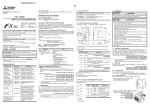
1.
1.1
1 Introduction
1.1 Features of the FX3U-64DP-M
Introduction
Features of the FX3U-64DP-M
The FX3U-64DP-M PROFIBUS-DP Master Block (hereafter called "64DP-M") is a master (Class 1) for the
PROFIBUS-DP network. The FX3U Series PLC, when connected to the 64DP-M can read input data from the
DP-Slaves, and write output data to the DP-Slaves. Only one 64DP-M can be connected directly to the FX3U
series PLC’s extension port, or to any other extension unit / block’s right side extension port.
1. Controlled maximum slaves:
A 64DP-M can control a maximum of 64 slaves using repeaters on the PROFIBUS-DP network.
→ For system configuration of the PROFIBUS-DP network, refer to Section 1.3
2. Communication data and message:
The 64DP-M communicates the following I/O data and messages from/to DP-Slaves on the PROFIBUS-DP
network.
→ For details, refer to Chapter 5 and 7
• Cyclic I/O data
• Acyclic I/O data
• Diagnostic messages
Diagnostic messages from DP-Slaves can be stacked to a maximum of 64 entries.
• Alarm Messages of alarm model
3. Global control:
The 64DP-M supports SYNC global control, UNSYNC global control, FREEZE global control and UNFREEZE
global control.
→ For details, refer to Chapter 5 and 7
4. Configuration setting:
Configuration of the 64DP-M can be set easily by GX Configurator-DP Configuration System for Open
Networks Software (Ver. 7.00A or more). For GX Configurator-DP Configuration System for Open Networks
Software (hereafter called “GX Configurator-DP"), refer to the following manual.
→ Refer to Chapter 6 and 8
→ For operation details on software, GX Configurator-DP Software Manual
5. Communication:
The 64DP-M supports 9.6k, 19.2k, 93.75k, 187.5k, 500k, 1.5M, 3M, 6M and 12Mbps.
The 64DP-M can be connected to a PROFIBUS-DP network by a standard 9-pin D-SUB connector and
shielded twisted pair PROFIBUS cable complying with EN50170.
→ For wiring, refer to Chapter 4
→ For parameter setting, refer to Chapter 6
12
FX3U-64DP-M PROFIBUS-DP Master Block
User’s Manual
1 Introduction
1.2 External Dimensions and Each Part Name
External Dimensions and Each Part Name
1.2.1
External Dimensions and Each Part Name
Introduction
1.2
1
2
[3]
[5]
[4]
Specifications
Dimensions: mm (inches)
MASS (Weight): Approx. 0.2kg (0.44 lbs)
Accessory: Special block No. label
[6]
3
[2]
80(3.15")
90(3.55")
Installation
[7]
4
Wiring
[1]
[8]
4(0.16")
5
9(0.36")
87(3.43")
Mode,
Data Comms.,
Global Control
43(1.7")
89(3.51")
[1] PROFIBUS-DP port (9-pin D-SUB Connector: #4-40unc inch screw thread)
6
[2] Extension cable
[4] Status LEDs
LED Name Color
Description
Lit
Green
Flicker
Unlit
TOKEN
Lit
64DP-M is in STOP mode, or an error has occurred.
→ For diagnostic details, refer to Section 9.1
Red
Flicker
Unlit
8
PLC access to 64DP-M by FROM/TO instruction.
PLC does not access to 64DP-M by FROM/TO instruction.
Hardware error has occurred.
→ For diagnostic details, refer to Section 9.1 and 9.2
An error or problem has occurred.
→ For diagnostic details, refer to Section 9.1 and 9.2
During normal operation.
Lit while 24V DC power is properly supplied from main unit.
→ For other LED status, refer to Section 9.1
[5] Extension port under the top cover
[6] Name plate
[7] DIN rail mounting groove (DIN rail: DIN46277)
[8] DIN rail mounting hook
13
9
Diagnostics
Green
7
Example
Program
Unlit
Lit
POWER
→ For details, refer to Section 9.1
Green Lit when token is maintained.
FROM/TO Green
ERROR
Not all configurated DP-Slaves are in data exchange.
Setting
Parameters and
Configuration
RUN
During normal operation.
64DP-M is in RUN mode, all DP-Slaves exchange data in Data Exchange mode.
Allocation of
Buffer Memories
(BFMs)
[3] Direct mounting hole: 2-φ4.5 (0.18"), mounting screw: M4 screw
FX3U-64DP-M PROFIBUS-DP Master Block
User’s Manual
1.2.2
1 Introduction
1.3 System Configuration
Pin Configuration of PROFIBUS-DP Connector
5
4
3
RXD/TXD-P
Receive/transmit-Data-P
5
DGND
Data Ground
6
VP
Voltage-Plus (5V, 90mA)
2
8
RXD/TXD-N
Receive/transmit-Data-N
1, 2, 4, 7, 9
NC
Pin not assigned
6
7
3
8
9
Pin No.
1
The connector is a 9-pin D-SUB (#4-40unc inch screw thread) type, with the pin configuration shown below.
Signal Name
Meaning
Assigned
Not assigned
1.3
System Configuration
1.3.1
Applicable PROFIBUS-DP Network
• The maximum number of DP-Slaves that can be connected to a 64DP-M is 64.
• Number of units that can be connected for 1 segment
DP-Masters + DP-Slaves + repeaters ≤ 32 units
• Number of units that can be connected to the entire network using repeaters.
DP-Masters + DP-Slaves ≤ 126 units
• Communications can be conducted via a maximum of 3 repeaters from an arbitrary DP-Master or arbitrary
DP-Slave to an arbitrary DP-Master or arbitrary DP-Slave. However, the whole network can contain more
than 3 repeaters. (See note below.)
1. Connecting 1 Master (Class 1) on the PROFIBUS-DP network.
GX Configurator-DP
Ver. 7.00A or later
FX3U Series
PLC
FX3U-64DP-M
(Master of Class 1)
No.40 *1
Bus terminator
Bus terminator
PROFIBUS-DP Network
DP-Slave
No.1
*1.
14
DP-Slave
No.2
DP-Slave
No.3
DP-Slave
No.29
DP-Slave
No.30
DP-Slave
No.31
In this system configuration, the 64DP-M can connect a maximum of 31 slaves. As the total units (DPMasters + DP-Slaves + repeaters) is 32 units when PROFIBUS-DP network is 1 segment.
FX3U-64DP-M PROFIBUS-DP Master Block
User’s Manual
1 Introduction
1.3 System Configuration
1
GX Configurator-DP
Ver. 7.00A or later
FX3U Series
PLC
Introduction
2. Connecting 1 Master (Class 1) and 1 repeater on the PROFIBUS -DP network.
FX3U-64DP-M
(Master of Class 1)
No.80 *1
Bus terminator
Bus terminator
2
Specifications
PROFIBUS-DP Network
DP-Slave
No.2
DP-Slave
No.3
DP-Slave
No.29
DP-Slave
No.30
DP-Slave
No.31
DP-Slave
No.32
DP-Slave
No.33
DP-Slave
No.60
DP-Slave
No.61
Repeater
3
Installation
DP-Slave
No.1
In this system configuration, the 64DP-M can connect a maximum of 61 slaves, as a repeater is used.
Wiring
*1.
4
3. Connecting 1 Master (Class 1) and 3 repeaters on the PROFIBUS -DP network.
GX Configurator-DP
Ver. 7.00A or later
FX3U Series
PLC
FX3U-64DP-M
(Master of Class 1)
No.70 *1
Bus terminator
PROFIBUS-DP Network
DP-Slave
No.18
Repeater
DP-Slave
No.19
DP-Slave
No.20
DP-Slave
No.34
DP-Slave
No.35
DP-Slave
No.36
DP-Slave
No.37
DP-Slave
No.43
DP-Slave
No.44
DP-Slave
No.46
DP-Slave
No.47
DP-Slave
No.63
DP-Slave
No.64
DP-Slave
No.45
6
Repeater
7
Repeater
8
9
*1. Communications can be conducted via a maximum of 3 repeaters from an arbitrary DP-Master or
arbitrary DP-Slave to an arbitrary DP-Master or arbitrary DP-Slave. However, the whole network can
contain more than 3 repeaters.
15
Diagnostics
DP-Slave
No.17
Example
Program
DP-Slave
No.3
Setting
Parameters and
Configuration
DP-Slave
No.2
Allocation of
Buffer Memories
(BFMs)
DP-Slave
No.1
5
Mode,
Data Comms.,
Global Control
Bus terminator
FX3U-64DP-M PROFIBUS-DP Master Block
User’s Manual
1 Introduction
1.3 System Configuration
4. Connecting 126 stations (3 Masters + 60 Slaves or more) on the PROFIBUS-DP network.
→ Please see NOTE on the next page
FX3U-64DP-M
(Master of Class 1)
No.124 *1
FX3U Series
PLC
FX3U-64DP-M
(Master of Class 1)
No.125 *2
FX3U Series
PLC
FX3U-64DP-M
(Master of Class 1)
No.126 *3
FX3U Series
PLC
Bus
terminator
Bus terminator
PROFIBUS-DP Network
Repeater
DP-Slave No.1
DP-Slave No.16
DP-Slave No.17
DP-Slave No.23
DP-Slave No.24
DP-Slave No.51
DP-Slave No.52
Repeater
DP-Slave No.25
DP-Slave No.26
Repeater
Repeater
DP-Slave No.53
DP-Slave No.82
16
DP-Slave No.103
DP-Slave No.80
DP-Slave No.104
*1.
This 64DP -M has a total of 40 slaves (No.1 to 16, 25, 81 to 103).
*2.
This 64DP-M has a total of 36 slaves (No.17 to 23, 52 to 80)
*3.
This 64DP-M has a total of 47 slaves (No.24, 26 to 51, 104 to 123)
DP-Slave No.81
DP-Slave No.123
FX3U-64DP-M PROFIBUS-DP Master Block
User’s Manual
1 Introduction
1.3 System Configuration
1
In the multiple master network, when reconnecting a PROFIBUS cable to a DP-Master that is exchanging
data at allowed baud rate, the other DP-masters may stop the communication, and the slave outputs may be
turned OFF. To avoid this, connect the master PROFIBUS cable securely.
In addition, the following value must be set in a Multi master network:
Sum of PROFIBUS (bus) cycle time of all DP-Masters.
For multi master networks the calculation of Minimum Slave Interval (MSI)
Minimum Slave Interval
must be done by customer. The setup must be the same for all
DP-Masters.
Master
parameter
Transmission speed must be the same for all DP-Master.
Watchdog
Checked
Slave Watchdog
Set the slave watchdog timer setting value to larger than (TTR × G)/TS.
TTR: Target token rotation time (Unit: Bit Time)
G:
Gap update factor
TS: Transmission Speed (Unit: bps)
TTR
This setting value is the same as Minimum Slave Interval.
HSA
Highest station address of the whole PROFIBUS Network
4
Wiring
BFM #34 Bit 1
1.3.2
3
Transmission Speed
Installation
Bus parameter
2
Specifications
All DP-Master (64DP-M) Settings
Introduction
Note
ON
Applicable PLC
PLC Type
FX3U series PLC
Version
Ver. 2.21 or later
5
Mode,
Data Comms.,
Global Control
For setting up a system, only one 64DP-M can be connected directly to the FX3U series PLC’s extension port,
or to any other extension unit / block’s right side extension port.
The 64DP-M occupies 8 points of I/O on the FX3U’s expansion bus. The 8 points can be allocated from either
inputs or outputs. The maximum I/O for a FX3U system is 256 I/O.
6
When connecting two 64DP-M or more to FX3U PLC, a hardware error will occur in the FX3U PLC main unit
(Error code: K6107).
Allocation of
Buffer Memories
(BFMs)
Note
7
Setting
Parameters and
Configuration
8
Example
Program
9
Diagnostics
17
FX3U-64DP-M PROFIBUS-DP Master Block
User’s Manual
1.4
Communication Time
1.4.1
Communication Time
1 Introduction
1.4 Communication Time
The communication time is the data exchange time between the FX3U series PLC and DP-Slaves. The
expression below gives this communication time.
Communication time = Total PROFIBUS (bus) cycle time*1 for each DP-Slave + (2 × Scan time*2)
*1.
The PROFIBUS (bus) cycle time is a data update cycle time between the 64DP-M and DP-Slaves.
The BFM #6 to #8 show the PROFIBUS (bus) cycle time.
→ To obtain the PROFIBUS (Bus) Cycle Time, refer to Subsection 1.4.2 and Section 6.8
*2.
D8010 to D 8012 show the scan time of the PLC.
Note
The PROFIBUS cycle time and FROM/TO instruction operates asynchronously. If data is written to the 64DPM in the PROFIBUS cycle time, this data will move to the system area on the next PROFIBUS cycle time.
Reference
The FROM/TO Execution Time*1 varies as follows, depending on the data amount to be transferred.
*1.
This table is also applicable to the other instructions accessing the 64DP-M BFMs.
FROM/TO Execution Time details
Execution time in ON status (µs)
FNC
Instruction
No.
16-bit instruction 32-bit instruction
Execution time in OFF status (µs)
16-bit instruction
32-bit instruction
Note
FX3U-64DP-M
78
FROM
15 + 275n
15 + 390n
0.585
1.105
BFM#350 to #1373
79
TO
15 + 345n
15 + 490n
0.585
1.105
BFM#2350 to #3373
n: The number of transferred data
Note
• The execution times above are approximate values for the FX3U-64DP-M.
• The FROM/TO Execution Time varies depending on each special function block.
• It is not necessary to check the all DP-Slaves' cyclic I/O data in a single PROFIBUS Cycle Time.
18
FX3U-64DP-M PROFIBUS-DP Master Block
User’s Manual
1.4 Communication Time
1
PROFIBUS (Bus) Cycle Time
The figure in the next page explains the PROFIBUS (bus) cycle time for one DP-master. In this example there
are 3 slaves. The PROFIBUS (bus) cycle time needs to be as follows:
Number of slaves
PROFIBUS (bus) cycle time = the higher value of [MSI] or [
{Pt (DP-Slave (i)) + Tsdi (M)} + Lr]
i=1
2
Σ
Explanation of MSI, Pt (DP-Slave (i)), Treq (i), Max Tsdr (i), Tres (i), Tsdi (M), Lr see following table.
Description
The polling time of the DP-Slave = Treq (i) + Max Tsdr (i) + Tres (i)
Treq (i)
The request transmission time of the DP-Slave =
{(number of output bytes to this DP-Slave + 9) × 11} / transmission speed
Max tsdr (i)
Response time of the DP-slave =
(This value is recorded in this DP-Slave GSD file) / transmission speed
Tres (i)
Response transmission time of the DP-slave =
{(Number of input bytes from this DP-Slave + 9) × 11} / transmission speed
3
Installation
Pt (DP-Slave (i))
4
Wiring
Processing time of DP-master request/response =
(This value from the following table) / transmission speed
Transmission Speed [bps]
Tsdi (M)
Specifications
→ The BFMs #6 to #8 show the details on PROFIBUS (Bus) Cycle Time, refer to Section 6.8
Wording
Introduction
1.4.2
1 Introduction
Value for Tsdi (M) calculation
10
19.2k, 93.75k
15
187.5k, 500k
80
1.5M, 3M, 6M, 12M
150
Lr
Data refresh time = Max. 8 ms + 0.1 ms × number of DP-slaves
MSI
Minimum slave interval is set in the configuration software (GX Configurator-DP).
5
Mode,
Data Comms.,
Global Control
9.6k
6
Allocation of
Buffer Memories
(BFMs)
7
Setting
Parameters and
Configuration
8
Example
Program
9
Diagnostics
19
FX3U-64DP-M PROFIBUS-DP Master Block
User’s Manual
1 Introduction
1.4 Communication Time
Time
PLC
Write to BFM (TO
instruction, etc)
Read from BFM (FROM
instruction, etc)
BFM in the 64DP-M
Internal buffer in
64DP-M
DP-Slave No.1
DP-Slave No.2
DP-Slave No.3
c
Lr
d
e
Pt (DP-Slave 1)
c
f
d
e
Pt (DP-Slave 2)
c
f
d
e
Pt (DP-Slave 3)
f
PROFIBUS (bus) cycle time*1
c
d
e
f
*1.
This time is “Treq” for each DP-slave.
This time is “Maximum Tsdr” for each DP-slave.
This time is “Tres” for each DP-slave.
This time is Tsdi(M)
The PROFIBUS Cycle Time needs to be the larger value obtained from the expression in the previous
page, or the MSI. The MSI (Minimum Slave Interval) is the value set by GX Configurator-DP.
Note
The instructions to access BFMs (FROM/TO instruction, etc.) and the PROFIBUS (bus) cycle are asynchronous.
BFM #6 shows the precise cycle time to exchange data after the dwell time expires.
→ For details on the PROFIBUS (Bus) Cycle Time BFM #6 to #8, refer to Section 6.8
20
FX3U-64DP-M PROFIBUS-DP Master Block
User’s Manual
1 Introduction
1.4 Communication Time
1
Introduction
Reference
The PROFIBUS (bus) Cycle Time variance depends primarily on the number of DP-Slaves and the number of
I/O data bytes.
PROFIBUS Cycle Time measurement
2
200
160
140
120
1.5MBaud
12MBaud
100
3
80
Installation
PROFIBUS Cycle Time [ms]
Specifications
180
60
40
20
0
4
64
Wiring
32
2
4
8
16
1
Number of slaves (32 Byte Input / 32 Byte Output per slave)
5
Mode,
Data Comms.,
Global Control
6
Allocation of
Buffer Memories
(BFMs)
7
Setting
Parameters and
Configuration
8
Example
Program
9
Diagnostics
21
FX3U-64DP-M PROFIBUS-DP Master Block
User’s Manual
1.5
1 Introduction
1.5 System Start-up Procedure
System Start-up Procedure
FX3U-64DP-M
Refer to Chapter 1
Outline of system:
• Applicable PLC
• Applicable PROFIBUS configuration tool
Outline
Refer to Chapter 2
Check of specifications
Specifications:
• Operation environment
• Power supply specifications
• Performance specifications
- Maximum number of slaves / master
- Maximum Number of stations / segment
- Maximum number of repeaters
- Maximum bus length (depend on baud rate)
Refer to Chapter 1 and 2
System configuration
System configuration:
Refer to Chapter 3 and 4
Installation and wiring
Refer to Chapter 7
Communication setting for 64DP-M
Turn ON power
Installation:
• Arrangements
• Mounting
Wiring:
• Applicable cable and connector
• PROFIBUS-DP wiring
• Bus terminator
Configuration setting:
• Create network configuration by configuration
tool
• Set parameter for DP-Master and DP-Slave
Refer to Chapter 7
Test run (communication test)
Configuration/Communication test:
• Download project by the configuration tool
• Check communication status (RUN LED)
Refer to Chapter 5 and 6
Buffer memory:
• List of buffer memories
• Details of buffer memory
• For buffer memory read/write method,
refer to pragramming manual
Communication program:
→ For example program, refer to Chapter 8
• Cyclic communication program
• Error indication program
Create program
Refer to Chapter 9
If the error status data is abnormal,
refer to Chapter 9.
22
FX3U-64DP-M PROFIBUS-DP Master Block
User’s Manual
2 Specifications
1
Introduction
2.
Specifications
2
3
Installation
4
Wiring
• Make sure to have the following safety circuits outside of the PLC to ensure safe system operation even during
external power supply problems or PLC failure.
Otherwise, malfunctions may cause serious accidents.
1) An emergency stop circuit, a protection circuit, an interlock circuit for opposite movements, such as normal
and reverse rotations, and an interlock circuit for preventing damage to the machine at the upper and lower
positioning limits should be configured on the outside of the PLC.
2) Note that when the PLC CPU detects an error, such as a watchdog timer error, during self-diagnosis, all
outputs are turned off. Also, when an error that cannot be detected by the PLC CPU occurs in an input/output
control block, output control may be disabled.
Design external circuits and mechanisms to ensure safe operations of the machine in such a case.
3) Note that when some sort of error occurs in a relay, triac or transistor of the output unit/block, output may be
kept on or off.
For output signals that may lead to serious accidents, design external circuits and mechanisms to ensure
safe operations of the machine.
Specifications
DESIGN PRECAUTIONS
5
6
Allocation of
Buffer Memories
(BFMs)
• Make sure to observe the precautions below to prevent damages to the system due to the abnormal data writing
by noise to the PLC:
1) Do not bundle the control line together with or lay it close to the main circuit or power line. As a guideline, lay
the control line at least 100mm (3.94") or more away from the main circuit or power line. Noise may cause
malfunctions.
2) Ground the shield wire with the PLC. Do not ground together with high voltage lines.
• Install module so that excessive force will not be applied to peripheral device connectors. Failure to do so may
result in wire damage/breakage or PLC failure.
Mode,
Data Comms.,
Global Control
DESIGN PRECAUTIONS
7
STARTUP AND MAINTENANCE
PRECAUTIONS
8
Example
Program
• Do not touch any terminal while the PLC’s power is on.
Doing so may cause electric shock or malfunctions.
• Before cleaning or retightening terminals, externally cut off all phases of the power supply.
Failure to do so may cause electric shock.
• Before modifying or disrupting the program in operation or running the PLC, carefully read through this manual
and the associated manuals and ensure the safety of the operation.
An operation error may damage the machinery or cause accidents.
Setting
Parameters and
Configuration
STARTUP AND MAINTENANCE
PRECAUTIONS
9
Diagnostics
• Do not disassemble or modify the unit.
Doing so may cause fire, equipment failures, or malfunctions.
* For repair, contact your local Mitsubishi Electric distributor.
• Do not drop the product and exert strong impact. Doing so may cause damage.
• Turn off the power to the PLC before attaching or detaching the peripheral devices.
Failure to do so may cause equipment failures or malfunctions.
23
FX3U-64DP-M PROFIBUS-DP Master Block
User’s Manual
2 Specifications
2.1 General Specifications
DISPOSAL PRECAUTIONS
• Please contact a certified electronic waste disposal company for the environmentally safe recycling and disposal
of your device.
TRANSPORT AND STORAGE
PRECAUTIONS
• The PLC is a precision instrument. During transportation, avoid impacts. After transportation, verify the operations
of the products.
2.1
General Specifications
For the general specification, refer to the manual of the PLC main unit.
The items other than the following are equivalent to those of the PLC main unit.
However, please don't perform any dielectric withstand voltage tests and insulation resistance tests to this
product.
→ Refer to FX3U PLC Hardware Edition
Item
Withstand voltage
Insulation resistance
2.2
Conformance to JEM-1021
5 MΩ or more by 500 V DC Between communication connector frame and ground
terminal of PLC main unit
Megger
Power Supply Specifications
Items
Internal Power Supply
24
Specifications
500 V AC for 1 min
Description
155 mA at 24V DC is supplied from the internal power supply (service power supply) in
main unit via extension cable.
FX3U-64DP-M PROFIBUS-DP Master Block
User’s Manual
2.3 Performance Specifications
1
Performance Specifications
Item
Introduction
2.3
2 Specifications
Specifications
Transmission Type
Bus network
Unit Type
PROFIBUS-DP master Class 1
2
Maximum Number of
FX3U-64DP-M at one PLC
Specifications
Transmission Data
Normal service mode:
32 byte/slave
(Maximum Exchanged Data Length) Extended service mode (default): 244 byte/slave
1 unit
Maximum Number of FX3U-64DP-M 3 units
In case of multi master configuration, all master stations must be FX3U-64DP-M.
at one PROFIBUS-DP Network
3 units
Maximum Number of
Stations / Segment
32 stations
Maximum Number of
Slaves / Master
64 slaves
No. of Connectable Nodes
31, 61 (1), 91 (2), 121 (3)
9.6k, 19.2k, 93.75k
1,200 m (3,937') / segment
187.5k
1,000 m (3,281') / segment
500k
400 m (1,312') / segment
1.5 M
200 m (656') / segment
3M, 6M, 12M
100 m (328') / segment
Connector
→ Refer to Note 1
5
“F364” hex
PROFIBUS-DP
Network
Port for PROFIBUS-DP network (9 pin D-SUB Connector)
Global Control
Synchronization,
supported.
Terminal Resistor
Not built in.
unsynchronization,
freeze
and
unfreeze
modes
6
8 points taken from the PLC extension bus (can be either input or output)
Applicable PLC
FX3U Series PLC
RUN LED
FROM/TO LED
TOKEN LED
ERROR LED
→ For other LED status, refer to Section 9.1
Lit: During normal operation
→ For other LED status, refer to Section 9.1
Lit when a FROM/TO instruction from the PLC is in operation.
Lit when token is maintained.
Unlit: During normal operation.
→ For other LED status, refer to Section 9.1 and 9.2
Transmission
Speed (bps)
Maximum Bus Length
No repeater
1 repeater
2 repeaters
3 repeaters
2,400 m (7,874') 3,600 m (11,811') 4,800 m (15,748')
187.5k
1,000 m (3,281')
2,000 m (6,562')
3,000 (9,843')
4,000 m (13,123')
400 m (1,312')
800 m (2,625')
1,200 m (3,937')
1,600 m (5,249')
1.5 M
200 m (656')
400 m (1,312')
600 m (1,969')
800 m (2,625')
3M, 6M, 12M
100 m (328')
200 m (656')
300 m (984')
400 m (1,312')
9
Diagnostics
9.6k, 19.2k, 93.75k 1,200 m (3,937')
500k
8
Example
Program
Note 1
Length that the bus can be expanded by using repeaters.
Maximum Bus Length = (No. of repeaters + 1) × (Bus Length / segment)
7
Setting
Parameters and
Configuration
LED indicators
Lit when 24V DC power is supplied form the PLC or external power supply.
Allocation of
Buffer Memories
(BFMs)
Number of occupied I/O points
POWER LED
are
Mode,
Data Comms.,
Global Control
PNO ID
4
Wiring
Supported
Transmission
Speed (bps)
and Bus
Length
3
Installation
Maximum Number of
Repeaters / Communication Path
25
FX3U-64DP-M PROFIBUS-DP Master Block
User’s Manual
3.
3 Installation
Installation
DESIGN PRECAUTIONS
• Make sure to have the following safety circuits outside of the PLC to ensure safe system operation even during
external power supply problems or PLC failure.
Otherwise, malfunctions may cause serious accidents.
1) An emergency stop circuit, a protection circuit, an interlock circuit for opposite movements, such as normal
and reverse rotations, and an interlock circuit for preventing damage to the machine at the upper and lower
positioning limits should be configured on the outside of the PLC.
2) Note that when the PLC CPU detects an error, such as a watchdog timer error, during self-diagnosis, all
outputs are turned off. Also, when an error that cannot be detected by the PLC CPU occurs in an input/output
control block, output control may be disabled.
Design external circuits and mechanisms to ensure safe operations of the machine in such a case.
3) Note that when some sort of error occurs in a relay, triac or transistor of the output unit/block, output may be
kept on or off.
For output signals that may lead to serious accidents, design external circuits and mechanisms to ensure
safe operations of the machine.
DESIGN PRECAUTIONS
• Make sure to observe the precautions below to prevent damages to the system due to the abnormal data writing
by noise to the PLC:
1) Do not bundle the control line together with or lay it close to the main circuit or power line. As a guideline, lay
the control line at least 100mm (3.94") or more away from the main circuit or power line. Noise may cause
malfunctions.
2) Ground the shield wire with the PLC. Do not ground together with high voltage lines.
• Install module so that excessive force will not be applied to peripheral device connectors. Failure to do so may
result in wire damage/breakage or PLC failure.
INSTALLATION PRECAUTIONS
• Make sure to cut off all phases of the power supply externally before attempting installation or wiring work.
Failure to do so may cause electric shock.
26
FX3U-64DP-M PROFIBUS-DP Master Block
User’s Manual
3 Installation
1
Introduction
INSTALLATION PRECAUTIONS
2
Specifications
3
Installation
• Use the product within the generic environment specifications described in the PLC main unit manual (Hardware
Edition).
Never use the product in areas with dust, oily smoke, conductive dusts, corrosive gas (salt air, Cl2, H2S, SO2, or
NO2), flammable gas, vibration or impacts, or exposed to high temperature, condensation, or wind and rain.
If the product is used in such conditions, electric shock, fire, malfunction, deterioration or damage may occur.
• Install the product securely using a DIN rail or mounting screws.
• Install the product on a flat surface.
If the mounting surface is rough, undue force will be applied to the PC board, thereby causing nonconformities.
• When drilling screw holes or wiring, make sure cutting or wire debris does not enter the ventilation slits.
Failure to do so may cause fire, equipment failures or malfunctions.
• Be sure to remove the dust proof sheet from the PLC's ventilation port when the installation work is completed.
Failure to do so may cause fires, equipment failures, and malfunctions.
• Connect the extension and communication cables securely to their designated connectors.Unsecured connection
may cause malfunctions.
• Do not touch the conductive parts of the product directly to avoid failure or malfunction.
4
Wiring
5
Mode,
Data Comms.,
Global Control
6
Allocation of
Buffer Memories
(BFMs)
7
Setting
Parameters and
Configuration
8
Example
Program
9
Diagnostics
27
FX3U-64DP-M PROFIBUS-DP Master Block
User’s Manual
3.1
3 Installation
3.1 Arrangements
Arrangements
The 64DP-M connects on the right side of an FX3U series main unit or extension units/blocks (including
special function units/blocks).
However, PLC can connect extension equipment to both the right and left-hand sides. When planning to add
additional extension equipment in the future, please keep the appropriate space available on both sides of the
main unit.
For further information of installation arrangements, refer to the following manual.
→ FX3U PLC Hardware Edition
Note
• Keep a space of 50 mm (1.97") or more between the unit main body and other devices and structures.
Install the unit as far from high-voltage lines, high-voltage devices and power equipment as possible.
A
FX3U Series
main unit
A
FX3U-64DP-M
A
A
A ≥ 50mm (1.97")
• To prevent temperature rise, do not install the PLC on a floor or a ceiling or in the vertical direction.
Install it horizontally on a wall as shown below.
• Arrange the extension cable in such a way that the left connectors of the I/O extension units/blocks or
special extension units/blocks are connected on the side closer to the main unit.
28
FX3U-64DP-M PROFIBUS-DP Master Block
User’s Manual
3.2 Mounting
1
Mounting
Introduction
3.2
3 Installation
The 64DP-M can be mounted on a DIN rail (DIN46227) or mounted directly using screws.
Direct Mounting
2
39
(1.54")
3
Installation
90 (3.55")
4
(0.16")
Specifications
The 64DP-M can be mounted with M4 screws by using the direct mounting holes.
The 64DP-M mounting hole pitches are shown below.
→ For details, refer to FX3U PLC Hardware Edition
80 (3.15")
3.2.1
4
Wiring
Point
• Mounting screw: M4 screw.
• An interval space between each unit of 1 to 2 mm (0.04" to 0.08") is necessary.
• Mount the main unit, I/O extension units/blocks, and special function units/blocks which are installed on the
left side of 64DP-M first.
1) Make mounting holes in the mounting surface referring to
the above diagram.
Mode,
Data Comms.,
Global Control
Direct Mounting Procedure
5
2) Fit the 64DP-M (right fig. A) based on the holes, and secure
it with M4 screws (right fig. B).
6
Allocation of
Buffer Memories
(BFMs)
FX
3U
-48
M
IN 0
10
1
11
2
12
3
13
4
14
5
15
6
16
7
17
20
21
T
0
10
1
7
22
23
24
25
26
PO
27
PO
WER
WER
RURU
N N
3
11
4
12
BA BA
5
TT TT
13
6
14
ERER
7
15
RORO
20
16
R R
21
17
22
23
24
25
Setting
Parameters and
Configuration
OU
2
26
27
B
8
Example
Program
A
B
3) Connect extension cable (right fig. C) to the main unit, I/O
extension unit/block, or special function unit/block to the left
side.
→ For extension cable connection procedure,
refer to FX3U PLC Hardware Edition
9
Diagnostics
29
FX3U-64DP-M PROFIBUS-DP Master Block
User’s Manual
3.2.2
3 Installation
3.2 Mounting
DIN Rail Mounting
The 64DP-M can be mounted on a DIN rail (DIN46227, 35mm width).
→ For details, refer to FX3U PLC Hardware Edition
Note
• DIN rail uses DIN 46227 (35mm width).
• An interval space between each unit of 1 to 2 mm (0.04" to 0.08") is necessary.
• Mount the main unit, I/O extension units/blocks, and special function units/blocks which are installed in the
left side of 64DP-M first.
DIN Rail Mounting Procedure
1) Fit the upper edge of the DIN rail mounting groove (right fig. A) onto the DIN
rail.
1)
2) Push the product onto the DIN rail.
A
2)
3) Connect extension cable (right fig.B) to the main unit, I/O
extension unit/block, or special function unit/block to the left
side.
→ For extension cable connection procedure,
refer to FX3U PLC Hardware Edition
Removing Procedure from DIN Rail
1) Disconnect the PROFIBUS-DP communication cable and extension cables.
2) Insert the tip of a screwdriver into the hole of the DIN rail mounting
hook (right fig. A).
3) Using a screwdriver as shown in the figure to the right, the DIN rail
mounting hook (right fig. A) is pulled out.
4) Remove the product from the DIN rail (right fig. B).
B
4)
A
3)
2)
30
FX3U-64DP-M PROFIBUS-DP Master Block
User’s Manual
4 Wiring
4.1 Applicable Cable and Connector
1
Introduction
4.
Wiring
2
3
Installation
• Make sure to observe the precautions below to prevent damages to the system due to the abnormal data writing
by noise to the PLC:
1) Do not bundle the control line together with or lay it close to the main circuit or power line. As a guideline, lay
the control line at least 100mm (3.94") or more away from the main circuit or power line. Noise may cause
malfunctions.
2) Ground the shield wire with the PLC. Do not ground together with high voltage lines.
• Install module so that excessive force will not be applied to peripheral device connectors. Failure to do so may
result in wire damage/breakage or PLC failure.
Specifications
DESIGN PRECAUTIONS
4
Wiring
WIRING PRECAUTIONS
• Cut off all phases of the power supply externally before installation or wiring work in order to avoid damage to the
product or electric shock.
Mode,
Data Comms.,
Global Control
WIRING PRECAUTIONS
• When drilling screw holes or wiring, make sure cutting or wire debris does not enter the ventilation slits.
Failure to do so may cause fire, equipment failures or malfunctions.
6
Allocation of
Buffer Memories
(BFMs)
4.1
Applicable Cable and Connector
The following table shows the applicable cable and connector for a PROFIBUS-DP network.
Item
Description
7
PROFIBUS-DP network cable Shielded twisted-pair PROFIBUS cable complying with EN50170
Applicable only to PROFIBUS connector
(9-pin D-SUB Connector: #4-40unc inch screw thread)
→ For PROFIBUS connectors, see the PROFIBUS connector manual
Setting
Parameters and
Configuration
Connector
5
8
Example
Program
9
Diagnostics
31
FX3U-64DP-M PROFIBUS-DP Master Block
User’s Manual
4.2
4 Wiring
4.2 PROFIBUS-DP Wiring
PROFIBUS-DP Wiring
To connect the 64DP-M to a PROFIBUS-DP network, use only the PROFIBUS connector and shielded
twisted-pair PROFIBUS cable complying with EN50170.
Shielded twisted-pair
PROFIBUS cable to
PROFIBUS-DP
network
PROFIBUS connector
FX3U-64DP-M
PROFIBUS-DP Master Block
For noise prevention please
attach at least 50 mm (1.97") of
the twisted-pair PROFIBUS cable
along the grounding plate to
which the ground terminal is
connected.
FX3U Series PLC
FX3U-64DP-M
PROFIBUS-DP
Master Block
Shielded twisted-pair
PROFIBUS cable
complying with EN50170
to PROFIBUS-DP network
Grounding plate
Grounding resistance of 100 Ω or less (Class D)
4.3
Grounding
Grounding should be performed as stated below.
• The grounding resistance should be 100Ω or less.
• Independent grounding should be performed for best results.
When independent grounding is not performed, perform "shared grounding" of the following figure.
PLC
Another
equipment
Independent grounding
Best condition
PLC
Another
equipment
Shared grounding
Good condition
PLC
Another
equipment
Common grounding
Not allowed
• The grounding wire size should be AWG 14 (2 mm2) or larger.
• The grounding point should be close to the PLC, and all grounding wire should be as short as possible.
4.4
Bus Terminator
The units at each end of the PROFIBUS-DP network must have a bus terminator. This will either be in the
DP-Master or DP-Slave unit or in the PROFIBUS connector.
However, the 64DP-M does not have a terminating resistance built-in.
32
FX3U-64DP-M PROFIBUS-DP Master Block
User’s Manual
5 Mode, Data Communication, Global Control
5.1 Cyclic I/O Data Communication
1
Mode, Data Communication, Global Control
2
Cyclic I/O Data Communication
64DP-M [Master (Class 1)]
Buffer memory
Read*1
Write*2
Input Data Area
for Cyclic Data
Communication
*1: FROM,or RBFM instructions,
BFM direct designation in applied
instruction
5
*2: TO,or WBFM instructions,
BFM direct designation in applied
instruction
Mode,
Data Comms.,
Global Control
Output Data Area
for Cyclic Data
Communication
PROFIBUS-DP Network
Input data
(image)
6
Allocation of
Buffer Memories
(BFMs)
Input data
(image)
Output data
(image)
Output data
(image)
7
Mode in Cyclic I/O Data Communication
BFM #39
Value
K3
Maximum Exchanged Data Length
Normal Service Mode
(mode 0)
Maximum 32 byte/slave
64DP-M can exchange 32 bytes (16 words) of cyclic I/O data to every DPSlave.
Maximum 244 byte/slave
Extended Service Mode 64DP-M can exchange 0 to 244 bytes of cyclic I/O data to each DP-Slave.
(mode 3)
However, the total cyclic I/O data for all the DP-Slaves has a maximum of
2048/2048 bytes.
33
9
Diagnostics
K0
Setting Mode
8
Example
Program
The 64DP-M has Normal Service Mode (mode 0) and Extended Service Mode (mode 3) in cyclic I/O data
communication, decided by BFM #39. In cyclic I/O data communication, the maximum exchanged data length
to DP-Slave is decided by this mode setting.
For the maximum exchanged data length, refer to the following table.
Moreover, the mode setting can be checked by value in BFM #39.
→ For mode setting [BFM #39], refer to Section 6.21
Setting
Parameters and
Configuration
Slaves
5.1.1
4
Wiring
FX3U PLC main Unit
3
Installation
Cyclic I/O Data Communication is used for periodic data communication (e.g. I/O, analog input value, etc.)
between 64DP-M and DP-Slaves. The 64DP-M can exchange data to DP-Slaves without using the Data
Consistency Mode in cyclic I/O data communication when I/O data is 16 bit or less.
However, the 64DP-M has to use the Data Consistency Mode to exchange data to DP-Slaves when I/O data is
more than 16 bit. Therefore, it shows by Cyclic I/O Data Consistency Activate/Deactivate flags in BFM #84 to
#87 and #92 to #95 whether Data Consistency Mode is necessary or not. This flag is set by each DP-Slave
Parameter Setting on GX Configurator-DP. (Depending on the DP-Slave, it may be set up automatically.)
→ For allocation of flags, refer to Section 6.4, 6.23, and 6.24
→ For details on Cyclic Input Data Area, refer to Section 6.23
→ For details on Cyclic Output Data Area, refer to Section 6.24
Specifications
5.1
Introduction
5.
FX3U-64DP-M PROFIBUS-DP Master Block
User’s Manual
5.1.2
5 Mode, Data Communication, Global Control
5.1 Cyclic I/O Data Communication
Normal Service Mode (Mode 0)
64DP-M can exchange 32 bytes (16 words) of cyclic I/O data to every DP-Slave as follows.
→ For Cyclic Input Data Area, refer to Section 6.23
→ For Cyclic Output Data Area, refer to Section 6.24
BFM Address
BFM Address
BFM #350
1st station
Input Data Area
#365
#366
Upper byte
2nd byte
4th byte
6th byte
8th byte
Lower byte
1st byte
3rd byte
5th byte
7th byte
#365
#366
#367
#368
#368
32th byte
2nd byte
4th byte
6th byte
8th byte
31th byte
1st byte
3rd byte
5th byte
7th byte
#381
32th byte
31th byte
#2350
#2351
#2352
#2353
2nd byte
4th byte
6th byte
8th byte
1st byte
3rd byte
5th byte
7th byte
#2365
#2366
#2367
#2368
#2369
32th byte
2nd byte
4th byte
6th byte
8th byte
31th byte
1st byte
3rd byte
5th byte
7th byte
#2381
32th byte
31th byte
BFM #350
#351
#352
#353
2nd station
#381
#382
3rd station
#397
#1358
64th station
#1373
#2350
1st station
Output Data Area
#2365
#2366
2nd station
#2381
#2382
3rd station
#2397
#3358
64th station
#3373
34
Bit 0
FX3U-64DP-M PROFIBUS-DP Master Block
User’s Manual
5.1 Cyclic I/O Data Communication
1
Extended Service Mode (Mode 3)
64DP-M can exchange 0 to 244 bytes of I/O data to each DP-Slave. The I/O data length of each DP-Slave is assigned
according to the parameter file set in the GX Configurator-DP.
However, total I/O data for all the DP-Slaves has a maximum of 2048/2048 bytes.
BFM Address
BFM Address
BFM #350
1st station
Lower byte
1st byte
3rd byte
5th byte
7th byte
#361
#362
#363
#364
#365
Not used
2nd byte
4th byte
6th byte
Not used
23th byte
1st byte
3rd byte
5th byte
7th byte
#2350
#2351
#2352
#2353
2nd byte
4th byte
6th byte
8th byte
1st byte
3rd byte
5th byte
7th byte
#2357
#2358
#2359
#2360
Not used
2nd byte
4th byte
6th byte
15th byte
1st byte
3rd byte
5th byte
BFM #350
#351
#352
#353
Bit 0
3
2nd station
#365
#366
3rd station
Installation
Input Data Area
#361
#362
Upper byte
2nd byte
4th byte
6th byte
8th byte
2
Specifications
→ For Cyclic Input Data Area, refer to Section 6.23
→ For Cyclic Output Data Area, refer to Section 6.24
Introduction
4
Wiring
64th station
#1373
#2350
#2357
#2358
5
Mode,
Data Comms.,
Global Control
1st station
2nd station
#2360
#2361
3rd station
6
Allocation of
Buffer Memories
(BFMs)
Output Data Area
5.1.3
5 Mode, Data Communication, Global Control
64th station
7
#3373
Setting
Parameters and
Configuration
8
Example
Program
9
Diagnostics
35
FX3U-64DP-M PROFIBUS-DP Master Block
User’s Manual
5.2
5 Mode, Data Communication, Global Control
5.2 Acyclic I/O Data Communication
Acyclic I/O Data Communication
The acyclic communication can be used for setting and change the DP-Slave parameter during cyclic
communication. The I/O data channel consists of 244 byte. Acyclic data communication has lower
communicative priority than cyclic data communication.
The 64DP-M has 4 data areas for each acyclic I/O communication.
→ For allocation of flags, refer to Section 6.4, 6.9, 6.25, and 6.26
→ For details on Acyclic Input Data Area, refer to Section 6.25
→ For details on Acyclic Output Data Area, refer to Section 6.26
Point
Acyclic I/O Data Communication can only be used in RUN (BFM #0 = K1), Clear (BFM #0 = K3) or AutoClear
(BFM #0 = K4) mode.
FX3U PLC main Unit
64DP-M [Master (Class 1)]
Buffer memory
Read*1
Write*2
Area 1
Area 2
Area 3
Area 4
Input Data Area
for Acyclic Data
Communication
Area 1
Area 2
Area 3
Area 4
Output Data Area
for Acyclic Data
Communication
*1: FROM or RBFM instructions,
BFM direct designation in applied
instruction
*2: TO or WBFM instructions,
BFM direct designation in applied
instruction
PROFIBUS-DP Network
Slaves
36
FX3U-64DP-M PROFIBUS-DP Master Block
User’s Manual
Diagnostic Information
5.3.1
Slave Diagnostic
5.3 Diagnostic Information
1
Introduction
5.3
5 Mode, Data Communication, Global Control
1. Direct read the current Slave Diagnostic Information
FX3U PLC main Unit
64DP-M [Master (Class 1)]
Buffer memory
Read*1
Internal Slave Diagnostic
FIFO Area
Diagnostic FIFO Data
(max. 64 information)
4
*2: TO or WBFM instructions,
BFM direct designation in
applied instruction
Current Slave
Diagnostic
Information
Request
*1: FROM or RBFM instructions,
BFM direct designation in
applied instruction
Wiring
Write*2
Slave
Diagnostic
Information
5
Slave Diagnostic Information for FIFO function
Mode,
Data Comms.,
Global Control
PROFIBUS-DP Network
6
Slaves
This function can only be used in RUN (BFM #0 = K1), Clear (BFM #0 = K3) or AutoClear (BFM #0 = K4) mode.
2. Slave Diagnostic FIFO (History)
FIFO
Diagnostic
Information
Data
Internal Slave Diagnostic
FIFO Area
Diagnostic FIFO Data
(max. 64 entries)
*1: FROM or RBFM instructions,
BFM direct designation in
applied instruction
*2: TO or WBFM instructions,
BFM direct designation in
applied instruction
Write*2
Example
Program
Read*1
8
64DP-M [Master (Class 1)]
Buffer memory
7
Setting
Parameters and
Configuration
The 64DP-M can stack the Slave Diagnostic Information to a maximum of 64 entries in the Internal Diagnostic
FIFO Area for all DP-Slaves. The Slave Diagnostic Information, which enters this Internal Diagnostic FIFO
Area can be read (stored) in BFM #7338 to #7463 as history by the FIFO function.
Moreover, after stocking up to 64 Slave Diagnostic Information in Internal Diagnostic FIFO Area, the new
Slave Diagnostic Information is not stocked (will be ignored).
→ For allocation of flags, refer to Section 6.4, 6.13, and 6.30
→ For details on Slave Diagnostic Information FIFO, refer to Section 6.30
Allocation of
Buffer Memories
(BFMs)
Point
FX3U PLC main Unit
3
Installation
The 64DP-M can directly read the current Slave Diagnostic Information from the selected DP-Slave by BFM
#7209, BFM #7210 to #7335.
→ For allocation of flags, refer to Section 6.4, 6.13, and 6.29
→ For details on Slave Diagnostic Information Data, refer to Section 6.29
2
Specifications
The 64DP-M can stack the Slave Diagnostic Information to a maximum of 64 entries in the Internal Diagnostic
FIFO Area for all DP-Slaves. Moreover, 64DP-M can read the current Slave Diagnostic Information from a
single specified DP-Slave.
9
Diagnostics
Slave Diagnostic Information for FIFO function
PROFIBUS-DP Network
Slaves
37
FX3U-64DP-M PROFIBUS-DP Master Block
User’s Manual
5.3.2
5 Mode, Data Communication, Global Control
5.4 Global Control
Alarm Message
The 64DP-M can handle Alarm Messages from the PROFIBUS-DPV1 slaves (alarm model).
When receiving an Alarm Message from the DP-Slave, 64DP-M should acknowledge receiving from the DPSlave. If 64DP-M does not acknowledge, the DP-Slave can not send a new alarm message.
Note
This function can only be used in RUN (BFM #0 = K1),Clear (BFM #0 = K3) or AutoClear (BFM #0 = K4) mode.
→ For allocation of flags, refer to Section 6.4, 6.13, and 6.32
→ For details on Alarm Message, refer to Section 6.32
FX3U PLC main Unit
64DP-M [Master (Class 1)]
Buffer memory
Read*1
Alarm
Message
Internal Alarm Message
FIFO Area
For each DP-Slave 2 Alarm
messages can be stocked
Write*2
*1: FROM or RBFM instructions,
BFM direct designation in
applied instruction
*2: TO or WBFM instructions,
BFM direct designation in
applied instruction
PROFIBUS-DP Network
Send acknowledge to DP-Slave.
Send Alarm Message to 64DP-M (master).
5.4
Slaves
Global Control
The 64DP-M supports SYNC/UNSYNC and FREEZE/UNFREEZE Global Control Service.
The 64DP-M is normally set as UNSYNC and UNFREEZE in Global Control Mode.
→ For allocation of setteing error flags, refer to Section 6.12
→ For details on Global Control Area, refer to Section 6.34
FX3U Series PLC
64DP-M [Master (Class 1)]
Buffer memory
Global Control Area
Example: Sending the Global Control command
to DP-Slaves in groups 1 and 2.
PROFIBUS-DP Network
Group 1
Group 5
Group 2
Group 8
38
FX3U-64DP-M PROFIBUS-DP Master Block
User’s Manual
5.4 Global Control
1
SYNC and UNSYNC Global Control
The SYNC/UNSYNC Global Control controls the output data communication from the 64DP-M to the DPSlave.
→ For details on Global Control, refer to Section 6.34
→ For Cyclic Output Data, refer to Section 5.1 and 6.34.1
64DP-M [Master (Class 1)]
Buffer memory
Cyclic Output Data Area
Global Control Area
(Group 1)
(Group 2)
DP-Slave 1
3
PROFIBUS-DP Network
(Group 1)
DP-Slave 2
Installation
Example: Sending the SYNC command to DP-Slaves in group 1.
(Group 1)
DP-Slave 3
2
Specifications
FX3U Series PLC
Introduction
5.4.1
5 Mode, Data Communication, Global Control
DP-Slave n
4
...
...
Wiring
...
...
. . . Output image memory: Data is always refreshed using polling.
. . . <During UNSYNC execution/default>
The output image memory value is output immediately (normal condition)
<During SYNC execution>
The output image memory value is only output once during the SYNC service timing.
5
Note
8
Example
Program
When using the SYNC Global Control command, output data (sent to the DP-Slave) is not refreshed until the
next SYNC or UNSYNC global command is sent to the DP-Slave. That is, even if new data is written to the
Output Data Area (BFM #2350 to #3373) by TO instructions, etc., it is not refreshed until the following SYNC
or UNSYNC global command is issued from the PROFIBUS-DP in SYNC Global Control Mode.
7
Setting
Parameters and
Configuration
2) UNSYNC Global Control command
When sending an UNSYNC Global Control command to a DP-Slave which is in SYNC mode, the DPSlave will be released from SYNC mode and will update the output data continuously.
By specifying a group of DP-Slaves in BFM #9390, the UNSYNC command is sent to arbitrary DPSlaves, similar to the SYNC command.
6
Allocation of
Buffer Memories
(BFMs)
1) SYNC Global Control command
In SYNC mode, the output data sent to DP-Slaves in the group specified by BFM #9390 is not
immediately written to the actual physical outputs of the DP-Slave. The output data are stored inside the
DP-Slaves until the next SYNC/UNSYNC Global Control command is sent, then the output data of those
DP-Slaves are updated. The first SYNC command sent to the DP-Slaves will switch them into SYNC
mode.
Mode,
Data Comms.,
Global Control
. . . Service SYNC (issued in the same group)
9
Diagnostics
39
FX3U-64DP-M PROFIBUS-DP Master Block
User’s Manual
5.4.2
5 Mode, Data Communication, Global Control
5.4 Global Control
FREEZE and UNFREEZE Global Control
The FREEZE/UNFREEZE Global Control controls the input data communication from the DP-Slave to the
64DP-M.
→ For datails on Global Control, refer to Section 6.34
→ For Cyclic Input Data, refer to Section 5.1 and 6.23
FX3U Series PLC
64DP-M [Master (Class 1)]
Buffer memory
Cyclic Input Data Area
Global Control Area
Example:Sending the FREEZE command to DP-Slaves in
group 3.
(Group 8)
(Group 3)
DP-Slave 1
...
PROFIBUS-DP Network
(Group 3)
DP-Slave 2
...
(Group 3)
DP-Slave 3
DP-Slave n
...
...
. . . Input image memory: The data is always refreshed by polling.
. . . <During UNFREEZE execution/default>
The actual input is input to the input memory immediately (normal condition)
<During FREEZE execution>
The actual input is input once into the input image memory at the FREEZE service timing.
. . . Service FREEZE (issued within the same group)
1) FREEZE Global Control command
In Freeze mode, the input data of DP-Slaves in the group specified by BFM #9390 is set to freeze (no
cyclical refresh of input data).
Only after sending another FREEZE/UNFREEZE Global Control command to the DP-Slaves, the input
data to the 64DP-M is updated.
2) UNFREEZE Global Control command
When sending an UNFREEZE Global Control command to a DP-Slave which is in FREEZE mode, the
DP-Slave will be released from FREEZE mode and update the input data continuously.
By specifying a group of DP-Slaves in BFM #9390, the UNFREEZE command can be performed on
arbitrary DP-Slaves, similar to the FREEZE command.
Note
When using FREEZE Global Control command, input data (received from DP-Slave) is not refreshed until
next FREEZE or UNFREEZE global command is send to the DP-Slave.
That is, even if the input (receive) data from the DP-Slave reads the Input Data Area (BFM #350 to #1373) by
FROM instructions, etc., this is not refreshed until the following FREEZE or UNFREEZE global command is
issued from the PROFIBUS-DP in FREEZE Global Control Mode.
40
FX3U-64DP-M PROFIBUS-DP Master Block
User’s Manual
6 Allocation of Buffer Memories (BFMs)
6.1 Buffer Memories (BFM) Lists
1
Allocation of Buffer Memories (BFMs)
2
Buffer Memories (BFM) Lists
BFM No.
Description
BFMs Access
read
write
Reference
Communication Status
3
-
6.2
BFM #1
Communication Control Flags
3
3
6.3
BFM #2
Consistency Handling Error Flags
3
3
6.4
BFM #3
PROFIBUS Error Flags
3
3
6.5
6.7
BFM #6
Current PROFIBUS (bus) cycle time for cyclic data exchange
3
-
BFM #7
Min. PROFIBUS (bus) cycle time for cyclic data exchange
3
-
BFM #8
Max. PROFIBUS (bus) cycle time for cyclic data exchange
3
-
BFM #9 to
BFM #17
Not used
-
-
-
BFM #18 to
BFM #21
Acyclic Slave Communication Deactivation Message Flags
3
3
6.9
BFM #22 to
BFM #25
Not used
-
-
-
BFM #26
PROFIBUS Module ID: PNO-Nr. F364 Hex
3
-
6.10
BFM #27
Master Reset
3
3
6.11
BFM #28
Setting Error Flags
3
3
6.12
BFM #29
Master Error Status
3
3
6.13
BFM #30
Module ID Code: K7140
3
-
6.14
BFM #31
PROFIBUS Master Address
3
-
6.15
BFM #32
PROFIBUS Transmission Speed
3
-
6.16
BFM #33
Clear Control Flag
3
3
6.17
BFM #34
PROFIBUS Error Mask Flag
3
3
6.18
BFM #35 to
BFM #37
Not used
-
-
-
BFM #38
Number of Allocated Slaves
3
-
6.19
BFM #39
Operation Service Mode
3
3
6.20
BFM #40 to
BFM #72
Not used
-
-
-
BFM #73 to
BFM #76
Data Swap Activate Flag
3
3
6.21
BFM #77 to
BFM #80
Not used
-
-
-
3
3
3
3
6.8
5
6
7
8
9
BFM #83
New Slave FDL address
3
3
BFM #84 to
BFM #87
Cyclic Input Data Consistency Activate/Deactivate Flags
3
3
6.23.1
BFM #88 to
BFM #91
Not used
-
-
-
BFM #92 to
BFM #95
Cyclic Output Data Consistency Activate/Deactivate Flags
3
3
6.24.1
6.22
41
Diagnostics
BFM #82
Change Slave FDL Address
Flag
This BFM is used to change the
Old Slave FDL address
Slave FDL address
BFM #81
4
Example
Program
6.6
-
Wiring
3
Setting
Parameters and
Configuration
3
3
Allocation of
Buffer Memories
(BFMs)
Dwell Time Flag / Whole Config Data Exchange Flag
Module READY Signal
Mode,
Data Comms.,
Global Control
BFM #4
BFM #5
3
Installation
BFM #0
Specifications
6.1
Introduction
6.
FX3U-64DP-M PROFIBUS-DP Master Block
User’s Manual
BFM No.
42
6 Allocation of Buffer Memories (BFMs)
6.1 Buffer Memories (BFM) Lists
Description
BFMs Access
Reference
read
write
-
-
-
3
3
6.23.2
BFM #96 to
BFM #99
Not used
BFM #100 to
BFM #163
Cyclic
Flags
BFM #164 to
BFM #224
Not used
-
-
-
BFM #225 to
BFM #288
This flag is used to exchange the
Cyclic Output Data Send Flags cyclic output data of more than 16
bits to DP-Slaves.
3
3
6.24.2
BFM #289 to
BFM #349
Not used
-
-
-
Input
Data
BFM #350 to
BFM #1373
Cyclic Input Data Area
BFM #1374 to
BFM #2349
Not used
Request
This flag is used to exchange the
cyclic input data of more than 16 bits
to DP-Slaves.
Reads input data of cyclic
communication from this area.
• Normal Service Mode (Mode 0):
32 bytes/slave
• Extended Service Mode
(Mode 3):
Maximum 244 bytes/slave, total
2048 bytes for all DP-Slaves
Writes output data of cyclic
communication to this area.
• Normal Service Mode (Mode 0):
32 bytes/slave
• Extended Service Mode
(Mode 3):
Maximum 244 bytes/slave, total
2048 bytes for all DP-Slaves
6.23.3
3
-
-
-
3
3
6.24.3
BFM #2350 to
BFM #3373
Cyclic Output Data Area
BFM #3374 to
BFM #4499
Not used
-
-
-
BFM #4500 to
BFM #4503
This flag is used to exchange the
Acyclic Input Data Request
Acyclic Input Data for each acyclic
Flags
DP-Slave channel.
3
3
6.25.1
BFM #4504 to
BFM #4509
Not used
-
-
-
BFM #4510 to
BFM #4513
Acyclic Output Data Send
Flags
3
3
6.26.1
BFM #4514 to
BFM #4519
Not used
-
-
-
3
3
6.25.2
-
-
-
3
3
6.26.2
-
-
-
BFM #4520 to
BFM #5015
Acyclic Input Data Area
BFM #5016 to
BFM #5759
Not used
BFM #5760 to
BFM #6255
Acyclic Output Data Area
BFM #6256 to
BFM #6999
Not used
This flag is used to exchange the
Acyclic Output Data for each acyclic
DP-Slave channel.
Reads input data of Acyclic
Communication for each acyclic DPSlave channel from this area.
4 acyclic DP-Slave channel,
maximum 240 (248) bytes/channel
Writes output data of Acyclic
Communication for each acyclic DPSlave channel to this area.
4 acyclic DP-Slave channel,
maximum 240 (248) bytes/channel
FX3U-64DP-M PROFIBUS-DP Master Block
User’s Manual
6 Allocation of Buffer Memories (BFMs)
6.1 Buffer Memories (BFM) Lists
1
Description
Master/Slave Internal
Parameter Error Flags
BFM #7004 to
BFM #7007
Not used
BFM #7008 to
BFM #7071
Master/Slave Internal
Parameter Error Data
BFM #7072 to
BFM #7199
Not used
Slave Diagnostic Status Flags
BFM #7204 to
BFM #7207
Not used
Checks this error data, when Master/
Slave Internal Parameter Error
occurs.
ON when receiving the Slave
Diagnostic Information from DPSlave.
BFM #7209
Slave Number
Writes to Slave number which stores
the current Slave Diagnostic
Information to BFM #7210 to #7335.
BFM #7210 to
BFM #7335
Slave Diagnostic Information Read the current Slave Diagnostic
Data
Information from this area.
3
6.27
-
-
-
3
3
6.28
-
-
-
3
3
6.29.1
-
-
-
2
3
4
3
3
6.29.2
3
3
6.29.3
3
-
6.29.4
FIFO Diagnostic Request
Sets to ON when storing the FIFO
Slave Diagnostic Information of
specified DP-Slave to BFM #7338 to
#7463.
3
3
6.30.1
BFM #7337
Internal FIFO Counter
This value is number of stocked
Slave Diagnostic Information in
Internal Diagnostic FIFO Area.
64DP-M can stock up to 64
information in Internal Diagnostic
FIFO Area.
3
-
6.30.2
BFM #7338 to
BFM #7463
Diagnostic FIFO Data Area
Reads the FIFO Slave Diagnostic
Information from this area.
3
-
6.30.3
BFM #7464 to
BFM #7591
Slave Diagnostic Status Data
Shows an overview of each DPSlave over the PROFIBUS
diagnosis.
3
-
6.31
BFM #7592 to
BFM #8783
Not used
-
-
-
3
3
6.32.1
-
-
-
3
-
6.32.2
-
-
-
BFM #7336
Not used
Alarm Acknowledge Status
BFM #8796 to
BFM #8799
Not used
8
9
43
Diagnostics
BFM #8792 to
BFM #8795
Shows the Alarm Acknowledge
status when not using Automatic
Acknowledge Function.
ON when a receiving Alarm was
read by the PLC program but not yet
Acknowledge.
7
Example
Program
BFM #8788 to
BFM #8791
6
Setting
Parameters and
Configuration
Automatical Acknowledge
Setting
5
Allocation of
Buffer Memories
(BFMs)
BFM #8784 to
BFM #8787
Sets this flag when using Automatic
Acknowledge Function for Alarm
Message.
Default setting:
PROFIBUS-DP V1 slave = 1
Wiring
Slave Diagnostic Request
3
Mode,
Data Comms.,
Global Control
BFM #7208
Sets to ON when storing the current
Slave Diagnostic Information of
specified DP-Slave by BFM #7209 to
BFM #7210 to #7335.
write
Installation
BFM #7200 to
BFM #7203
ON when Master/Slave Internal
Parameter Error occurs during DPSlave's initialization.
Reference
read
Specifications
BFM #7000 to
BFM #7003
BFMs Access
Introduction
BFM No.
FX3U-64DP-M PROFIBUS-DP Master Block
User’s Manual
BFM No.
44
6 Allocation of Buffer Memories (BFMs)
6.1 Buffer Memories (BFM) Lists
Description
BFM #8800 to
BFM #8803
Alarm Message Status
BFM #8804 to
BFM #8807
Not used
Shows Alarm Message Status when
using Automatic Acknowledge
Function.
ON when receiving Alarm Message
from DP-Slave.
Shows the number of stocked Alarm
Messages for each DP-Slave when
not using Automatic Acknowledge
Function.
64DP-M can stock up to 2 Alarm
Messages in Internal Alarm
Message FIFO Area.
BFMs Access
Reference
read
write
3
3
6.32.3
-
-
-
3
-
6.32.4
-
-
-
BFM #8808 to
BFM #8871
Alarm Message Counter
BFM #8872 to
BFM #8932
Not used
BFM #8933
Alarm Message Request
Sets to ON when storing the Alarm
Message of specified DP-Slave by
BFM #8934 to BFM #8935 to #8969.
3
3
6.32.5
BFM #8934
Request Slave Number
Write to slave number for storing the
Alarm Message to BFM #8935 to
#8969.
3
3
6.32.6
BFM #8935 to
BFM #8969
Alarm Message
Read the Alarm Message from this
area.
3
-
6.32.7
BFM #8970
Alarm ACK Request
Sets to ON when sending the
Acknowledge for Alarm Message to
specified DP-Slave by BFM #8971.
3
3
6.32.8
BFM #8971
Slave Number
Writes the slave number which
sends Acknowledge for Alarm
Message.
3
3
6.32.9
BFM #8972 to
BFM #9139
Not used
-
-
-
BFM #9140 to
BFM #9267
Address Information Area
3
-
6.33
BFM #9328 to
BFM #9389
Not used
-
-
-
BFM #9390
Global Control Area
3
3
6.34.1
BFM #9391 to
BFM #9393
Not used
-
-
-
BFM #9394
Writes the dwell time (in 1 second
steps) which does not detect
Information Dwell Time Setting Diagnostic Information after
exchange start.
Default: K4 (4 sec)
3
3
6.35
BFM #9395 to
BFM #9398
Not used
-
-
-
BFM #9399 to
BFM #9402
Cyclic Slave Status Area
3
-
6.36
BFM #9403 to
BFM #9406
Not used
-
-
-
Shows the Slave FDL address and I/
O data length of each project DPSlave.
Writes the Global Control Command
and groups when issuing Global
Control Command.
The status flag of corresponding DPSlave is ON when the I/O data via
cyclic communication exchanges.
FX3U-64DP-M PROFIBUS-DP Master Block
User’s Manual
6 Allocation of Buffer Memories (BFMs)
6.1 Buffer Memories (BFM) Lists
1
Description
The status flag of the corresponding
DP-Slave is ON when the I/O data is
being exchanged via Acyclic
Communication Exchange.
BFMs Access
Reference
read
write
3
-
6.37
Acyclic Slave Status Area
BFM #9411 to
BFM #9425
Not used
-
-
-
BFM #9426 to
BFM #9489
Cyclic Input Data Start Address Shows the starting address of cyclic
Area
input data for each DP-Slave.
3
-
6.38
BFM #9490 to
BFM #9550
Not used
-
-
-
BFM #9551 to
BFM #9614
Cyclic Output Data Start
Address Area
3
-
6.39
BFM #9615 to
BFM #9675
Not used
-
-
-
BFM #9676
Number of Configured Slaves
Shows the total number of
configured DP-Slaves.
3
-
6.40
BFM #9677 to
BFM #9868
Slave Number, Slave FDL
Address, Slave PNO ID
Shows the Slave Number, Slave
FDL address and PNO-ID of each
projected DP-Slave.
3
-
6.41
BFM #9869 to
BFM #10051
Not used
-
-
-
Installation
4
Wiring
Get Slave List Request
5
3
3
6.42.1
6
Allocation of
Buffer Memories
(BFMs)
Set to ON when using the
PROFIBUS Scan Function in all
modes except Cyclic Exchange
Mode.
Lists the following detected DPSlave information on PROFIBUS-DP
network when using this function.
• Configuration difference list
• Total number of detected DPSlave
• Slave Number, Slave FDL
address and PNO-ID of each
detected DP-Slave
3
Mode,
Data Comms.,
Global Control
BFM #10052
Shows the starting address of cyclic
output data for each DP-Slave.
2
Specifications
BFM #9407 to
BFM #9410
Introduction
BFM No.
7
-
6.42.2
3
-
6.42.3
BFM #10061
Scan Slave FDL Address
Shows the current scanned address.
After the scan, this value is set to 0.
May not show it because speed
scanning is faster in high baud rate
setting.
BFM #10062
Number of Detected Slave
Shows total number of detected DPSlaves.
3
-
6.42.4
Shows the Slave Number, Slave
FDL address and PNO-ID of each
detected DP-Slave.
3
-
6.42.5
9
-
-
-
Diagnostics
3
Setting
Parameters and
Configuration
The status flag of the corresponding
DP-Slave is ON when discrepancies
BFM #10053 to
Configuration Difference Satus exist between the projected
BFM #10060
configuration and the detected
configuration.
After
BFM #10444
Not used
Caution
Do not access the buffer memory that is marked as "Not used" (Ex. BFM #9 to #17, #22 to #25, #35 to #37,
#40 to #72, etc.) by FROM/TO instructions. There is a possibility to cause abnormal behavior to the operation
of the 64DP-M if accessing these buffer memories.
45
Example
Program
BFM #10063 to
Detected Slave List
BFM #10443
8
FX3U-64DP-M PROFIBUS-DP Master Block
User’s Manual
6.2
6 Allocation of Buffer Memories (BFMs)
6.2 Communication Status [BFM #0]
Communication Status [BFM #0]
BFM Access: Read Only
Communication status on PROFIBUS-DP network shows by the following value in BFM #0.
Value
46
Description
K0
64DP-M is in STOP mode.
K1
64DP-M is in RUN mode.
64DP-M can exchange data to DP-Slaves in this RUN mode.
K2
64DP-M is in Offline mode.
There is no communication and no Token on the PROFIBUS-DP network.
K3
64DP-M is in Clear mode.
64DP-M only reads Input data.
K4
64DP-M is in AutoClear mode.
64DP-M only reads Input data. 64DP-M changes in this mode when "Error Action Flag" is set up by
GX Configurator-DP and communication problem occurs on PROFIBUS-DP network.
FX3U-64DP-M PROFIBUS-DP Master Block
User’s Manual
6.3 Communication Control Flags [BFM #1]
1
Communication Control Flags [BFM #1]
BFM Access: Read / Write
The Communication Control Flags are allocated as described in the following table.
→ For details on the startup procedure, refer to the next page
Name
Description
2
Specifications
Bit No.
Introduction
6.3
6 Allocation of Buffer Memories (BFMs)
3
Bit 1 to 15
Not used
4
Installation
Bit 0
The Data Exchange Start Request Flag is used for exchanging
data between the 64DP-M and the DP-Slaves on the PROFIBUSDP network. If this Bit is set to ON, the PROFIBUS Mode changes
from STOP mode to RUN mode. Before turning this bit ON, the
64DP-M must be in STOP mode, Clear or AutoClear mode (BFM
Data Exchange Start Request
#0).
Flag
Changing this Bit from ON to OFF sets the PROFIBUS Mode from
RUN mode to STOP mode.
If the PLC is switched from RUN to STOP mode or if the PLC has
a PROG error or CPU error, the 64DP-M will automatically be set
to STOP mode.
Wiring
: By user program
: Automatically by 64DP-M
Module READY Signal
(BFM #5, Bit 0)
5
Mode,
Data Comms.,
Global Control
The initial output data is
writen to the Cyclic Output
Data Area (BFM #2350 to
#3373) by TO instruction,
etc.
BFM #5, bit 0 = ON
Write
Reset Data Exchange Start Request
Flag (BFM #1 Bit 0)
Exchange Start End Flags BFM #0
is set to 1 by 64DP-M to indicate
Data Exchange Mode (RUN)
6
BFM #1, bit 0 = ON
data exchange mode
(RUN)
BFM #0 = K1
Exchange Start End Flags
BFM #0 is reset to 0 by
64DP-M to indicate STOP mode
Whole Config Data Exchange Flag
BFM #4 Bit 1 is set to ON by 64DP-M
to indicate that all projected DP-Slaves
are performing data exchange
Whole Config Data Exchange
Flag BFM #4 Bit 1 is reset by
64DP-M
BFM #4 = K3
8
Example
Program
The Dwell Time Flag BFM #4 Bit 0 is set to ON
after expiration of the Dwell Time (BFM #9394).
After this point all startup diagnostic messages
will be cleared and the user program can perform
normal data exchange with the DP-Slaves, if
BFM #29 shows no error.
ON
7
Setting
Parameters and
Configuration
All projected DP-Slaves are
exchanging data with 64DP-M.
Allocation of
Buffer Memories
(BFMs)
Set Data Exchange Start Request
Flag (BFM #1 Bit 0) to ON
Dwell Time Flag BFM #4 Bit 0 is
reset by 64DP-M
9
Diagnostics
All projected DP-Slaves are exchanging
data with 64DP-M and the dwell time flag
has been expired.
47
FX3U-64DP-M PROFIBUS-DP Master Block
User’s Manual
6.4
6 Allocation of Buffer Memories (BFMs)
6.4 Consistency Handling Error Flags [BFM #2]
Consistency Handling Error Flags [BFM #2]
BFM Access: Read / Write
These Bits show the reasons for a consistency error. These Bits can be reset by writing a 0 to each Bit.
If any of these Bits are ON, the corresponding Bit in BFM #29 Bit 5 will also be ON. Resetting BFM #29 Bit 5
will also clear BFM #2 to K0.
An error will occur if reading/writing BFMs during the respective consistency flag are not turned to OFF.
Bit No.
48
Name
Description
Bit 0
Cyclic Input Data Exchange
Consistency Error
This Bit is set to ON if reading input data from a DP-Slave, while the Input
Data Consistency Flag of this DP-Slave is ON.
Bit 1
Cyclic Output Data Exchange
Consistency Error
This Bit is set to ON if writing output data to a DP-Slave, while the Output
Data Consistency Flag of this DP-Slave is ON.
Bit 2
Acyclic Input Data Exchange
Consistency Error
This Bit is set to ON if reading input data from acyclic input, while the
Acyclic Input Data Request Flag of this channel is ON.
Bit 3
Acyclic Input Data Request
Exchange Consistency Error
This Bit is set to ON if writing a request to an acyclic input channel, while
the Acyclic Input Data Request Flag of this channel is ON.
Bit 4
Acyclic Output Data Exchange
Consistency Error
This Bit is set to ON if writing output data to a acyclic output channel, while
the Acyclic Output Data Send Flag of this channel is ON.
Bit 5
Acyclic Output Data Request
Exchange Consistency Error
This Bit is set to ON if writing a request to an acyclic output channel, while
the Acyclic Output Data Send Flag of this channel is ON.
Bit 6
Slave Diagnostic Read
Consistency Error
This Bit is set to ON if reading diagnostic information from a DP-Slave,
while the Slave Diagnostic Request Flag of this DP-Slave is ON.
Bit 7
Slave Diagnostic Read Request This Bit is set to ON if writing a diagnostic information request to a DPConsistency Error
Slave, while the Slave Diagnostic Request Flag of this DP-Slave is ON.
Bit 8
FIFO Diagnostic Read
Consistency Error
Bit 9
FIFO Diagnostic Read Request This Bit is set to ON if writing a FIFO Diagnostic Request, while the FIFO
Consistency Error
Diagnostic Request Flag is ON.
Bit 10
Read Alarm Consistency Error
This Bit is set to ON if reading a Alarm Message, while the Alarm Message
Request Flag is ON.
Bit 11
Read Alarm Request
Consistency Error
This Bit is set to ON if writing a Alarm Message Request, while the Alarm
Message Request Flag is ON.
Bit 12
Alarm Acknowledge Write
Consistency Error
This Bit is set to ON if writing a new value to the Alarm ACK request Slave
Number, while the Alarm ACK request Flag is ON.
Bit 13
Alarm Acknowledge Write
Request Consistency Error
This Bit is set to ON if writing an Alarm ACK request, while the Alarm ACK
request Flag is ON.
Bit 14
Change Slave FDL Address
Consistency Error
This Bit is set to ON if reading the Slave FDL address, while the Change
Slave FDL Address Flag is ON.
Bit 15
Change Slave FDL Address
Request Consistency Error
This Bit is set to ON if writing a Slave FDL address Change Request, while
the Change Slave FDL Address Flag is ON.
This Bit is set to ON if reading a FIFO diagnostic information, while the
FIFO Diagnostic Request Flag is ON.
FX3U-64DP-M PROFIBUS-DP Master Block
User’s Manual
6.5 PROFIBUS Error Flags [BFM #3]
1
PROFIBUS Error Flags [BFM #3]
BFM Access: Read / Write
Bit No.
Name
Description
Bit 0
Conflict of Addresses
Conflict of addresses. The address of the 64DP-M has already
been assigned. If this error occurs, 64DP-M will change to Offline
mode. The 64DP-M has to be set to STOP mode before RUN mode
can be set.
Bit 1
Bus Protocol is disturbed
(faulty bus termination)
The bus protocol is disturbed. Possible causes are missing or faulty
termination resistors. If this error occurs, 64DP-M will change to
STOP mode unless BFM #34 Bit 0 is ON.
Installation
Bus Protocol is disturbed
The bus protocol is disturbed. Possible causes are stations beyond
the Highest Station Address (HSA), or the transmitted frame could
not be read back. If this error occurs, 64DP-M will change to Offline
mode. The 64DP-M has to be set to STOP mode before RUN mode
can be set.
4
Bit 3
Master State Hardware Error
Possible causes are deviations from required bus idle times, frames
longer than 256 bytes or interrupted data streams. If this error
occurs, 64DP-M will change to Offline mode. The 64DP-M has to
be set to STOP mode before RUN mode can be set.
Bit 4 to 15
Not used
Bit 2
The Communication Control Flags are allocated as follows.
Description
Dwell Time Flag
This flag is set to ON after expiration of the dwell time (BFM #9394).
Bit 1
This flag is set to ON after all projected PROFIBUS slaves have
Whole Config Data Exchange entered data exchange with the 64DP-M. If one or more DP-Slaves
Flag
of the downloaded GX Configurator-DP project are disconnected
from the PROFIBUS, this flag will be automatically reset.
Bit 2 to 15
Not used
7
Setting
Parameters and
Configuration
Bit 0
Allocation of
Buffer Memories
(BFMs)
BFM Access: Read Only
Name
5
6
Dwell Time Flag / Whole Config Data Exchange Flag [BFM #4]
Bit No.
Wiring
If any of Bit 0, Bit 2 or Bit 3 is ON while the 64DP-M is in cyclic data exchange (RUN) mode, the 64DP-M will
automatically change to Offline mode.
3
Mode,
Data Comms.,
Global Control
Note
6.6
2
Specifications
These Bits show the reasons for a PROFIBUS error. If any of these Bits are ON, the corresponding Bit in BFM
#29 Bit 8 will also be ON. These Bits can be reset by writing a 0 to each Bit. Resetting BFM #29 Bit 8 will also
clear BFM #3 to 0.
An error occurs if there is a problem with the PROFIBUS.
Introduction
6.5
6 Allocation of Buffer Memories (BFMs)
8
• For startup of the PROFIBUS network, it is advisable to evaluate the content of BFM #4 in the user program.
Only after the dwell time has expired and all DP-Slaves are in data exchange is it safe to trust the input data
of the DP-Slaves in the 64DP-M’s BFM. If the content of BFM #4 is different from K3, either not all DPSlaves are participating in cyclic data exchange, or the dwell time has not expired yet, which means that
there might be DP-Slaves that have a diagnostics Information which is not yet recognized by the 64DP-M.
49
9
Diagnostics
• If it is essential to the application that the communication is discontinued in case of an error, the “Error
Action Flag” in GX Configurator-DP (Master Settings) “Goto Clear Flag” should be selected. Additionally,
the watchdog timer for the cyclic communication with the DP-Slaves should be set.
Example
Program
Note
FX3U-64DP-M PROFIBUS-DP Master Block
User’s Manual
6.7
6 Allocation of Buffer Memories (BFMs)
6.7 Module READY Signal [BFM #5]
Module READY Signal [BFM #5]
BFM Access: Read Only
The Module READY Signal is allocated as follows.
Bit No.
6.8
Name
Description
Bit 0
Module READY Signal
Bit 1 to 15
Not used
During startup (boot) time of the 64DP-M, the Module READY
Signal is ON. After the 64DP-M has completed the internal
startup procedure and all BFMs are initialized, the flag is set
to ON.
Data exchange (BFM #1) should start after this flag becomes
ON (BFM #5 = K1).
PROFIBUS (Bus) Cycle Time [BFM #6 to #8]
BFM Access: Read Only
The PROFIBUS (bus) cycle time is the time between two data exchange cycles of one DP-Slave. The value is
adjusted in 1 ms steps.
BFM No.
Description
BFM #6
Current PROFIBUS (bus) cycle time; Default value: 0
BFM #7
Min. PROFIBUS (bus) cycle time; Default value: FFFF (hex)
BFM #8
Max. PROFIBUS (bus) cycle time; Default value: 0
The current PROFIBUS (bus) cycle time can be seen from BFM #6 during data exchange. The minimum /
maximum PROFIBUS (bus) cycle time can be seen from BFM #7 / #8 during data exchange after expiration
of the dwell time. The setting of the DP-Slave watchdog time in the GX Configurator-DP must be longer than
the maximum PROFIBUS (bus) cycle time (BFM #8).
6.9
Acyclic Slave Communication Deactivation Message Flags
[BFM #18 to #21]
BFM Access: Read / Write (only reset to 0)
These Bits show the deactivation message of the Acyclic Communication for each DP-Slave. If the Bit is ON,
then the Acyclic Communication with this Salve has been stopped. These flags are turned on by the 64DP-M
if an error has occurred during Acyclic Communication, or in General, after the 64DP-M has switched to
STOP mode during slave Acyclic Communication. The reasons for closing the Acyclic Communication
channel can be that a DP-Slave is not participating in acyclic communication any more, the DP-Slave is
receiving new parameter data while in cyclic communication mode, or the watchdog timer of the DP-Slave
has expired. If BFM #18 to #21 is different from 0, the corresponding error Bit in BFM #29 Bit 7 will be set to
ON. Resetting BFM #29 Bit 7 will also clear the contents of BFM #18 to #21. Switching the 64DP-M from
STOP mode to RUN mode (cyclic data exchange), will also clear the contents of BFM #18 to #21.
BFM No.
BFM #18
BFM No.
Bit 0
1
Bit 0
33
Bit 1
2
Bit 1
34
Bit 2
3
Bit 2
35
BFM #20
Bit No.
Station No.
....
....
....
Bit 15
16
Bit 15
48
Bit 0
17
Bit 0
49
Bit 1
18
Bit 1
50
Bit 2
19
Bit 2
51
BFM #21
....
....
....
....
50
Station No.
....
BFM #19
Bit No.
Bit 15
32
Bit 15
64
FX3U-64DP-M PROFIBUS-DP Master Block
User’s Manual
6.10 PROFIBUS Module ID (PNO ID) [BFM #26]
1
PROFIBUS Module ID (PNO ID) [BFM #26]
BFM Access: Read Only
Introduction
6.10
6 Allocation of Buffer Memories (BFMs)
Shows the PROFIBUS Module ID from PNO. The value is “F364” Hex.
2
Master Reset [BFM #27]
BFM Access: Read / Write
When the Master Reset Request is set to K2 the 64DP-M will do a Hardware reset. This reset is equivalent to
a Power down reset. After the reset, this Register will automatically be erased to K0.
Setting Error Flags [BFM #28]
BFM Access: Read / Write
The following table shows the reasons for a setting error BFM #29 Bit 4. The Bits can be reset by writing a 0
to each Bit.
Description
4
Wiring
Bit No.
3
Installation
6.12
Specifications
6.11
Bit 0
Write access to “Not used” or “read only” BFM has occurred
Bit 1
Wrong value was written to BFM #1 (Communication Control Flag), to BFM #33 (Clear Control Flag) or
to BFM #34 (PROFIBUS Error Mask Flag)
Bit 2
Not used
Bit 3
Wrong value was written to BFM #27 (Master Reset)
Bit 4
• Wrong value was written to BFM #39 (Operation Mode)
• Write access to BFM #39 while 64DP-M was not in STOP or Offline mode
Bit 5
• Wrong value was written to BFM #81 to #83 (Change Slave FDL Address)
• Write access while 64DP-M was not in STOP mode (Change Slave FDL Address)
Bit 6
• Wrong value was written to BFM #100 to #163 (Cyclic Input Data Request Flag)
• Wrong value was written to BFM #225 to #288 (Cyclic Output Data Send Flag)
Bit 7
• Wrong value was written to BFM #4500 to #4503 (Acyclic Input Data Request Flag)
• Unused slave number was written to acyclic input request channel BFM #4520, #4644, #4768 or
#4892
• Write request while 64DP-M is in STOP or Offline mode
Bit 8
• Wrong value was written to BFM #4510 to #4513 (Acyclic Output Data Send Flag)
• Unused slave number was written to acyclic output request channel BFM #5760, #5884, #6008 or
#6132
• Write request while 64DP-M is in STOP or Offline mode
Bit 9
• Wrong request value was written to BFM #7208
• Unused slave number was written to BFM #7209
• Write request while 64DP-M is in STOP or Offline mode (Slave Diagnostic)
Bit 10
• Wrong request value was written to BFM #7336 (FIFO Diagnostic request)
• Wrong value was written to BFM #7337 (only K0 is allowed)
Bit 11
• Wrong value was written to BFM #8933
• Unused slave number was written to BFM #8934
• Write request was executed while 64DP-M was in STOP or Offline mode (slave alarm)
Bit 12
• Wrong value was written to BFM #8970
• Unused slave number was written to BFM #8971
• Write request was executed while 64DP-M was in STOP or Offline mode (slave alarm acknowledge)
Bit 13
• Wrong value was written to BFM #9390
• Write request was executed while 64DP-M was in STOP or Offline mode (Global Control Area)
Bit 14
• Wrong value was written to BFM #9394 (Information Dwell Time Setting)
Bit 15
• Wrong value was written to BFM #10052
• Write request was executed while 64DP-M was not in STOP mode (Get slave list request)
5
Mode,
Data Comms.,
Global Control
6
Allocation of
Buffer Memories
(BFMs)
7
Setting
Parameters and
Configuration
8
Example
Program
Diagnostics
51
9
FX3U-64DP-M PROFIBUS-DP Master Block
User’s Manual
6.13
6 Allocation of Buffer Memories (BFMs)
6.13 Master Error Status [BFM #29]
Master Error Status [BFM #29]
BFM Access: Read / Write
The Master Status buffer memory is allocated as shown in the following table. All Bits (0 to 15) are latched
until turned OFF by user program, or until power down or next reset. Switching the 64DP-M from STOP mode
into RUN mode (data exchange mode), will also clear the latched error flags if the error does not exist any
more.
Bit No.
Name
Description
Reference
(Subsection)
Bit 0
Master Reset Status Flag
ON when the value of the Master Reset buffer memory
(BFM #27) is “K2”.
6.13.1
Bit 1
Master Hardware Error
ON when there is a Hardware error
6.13.2
Bit 2
Not used
-
Bit 3
Slave Parameter Error
ON when the 64DP-M has detected a parameter error at a
DP-Slave.
Bit 4
Setting Error Flag
ON when the user settings are wrong.
6.13.4
Bit 5
Consistency Error Flag
ON when there is an error in consistency handling
6.13.5
Bit 6
Not used
Bit 7
Acyclic Communication
Deactivation Flag
ON when the Acyclic Communication channel of a
DP-Slave is deactivated.
6.13.6
Bit 8
PROFIBUS Error
ON when there is a PROFIBUS error.
6.13.7
Bit 9
Slave Diagnosis Available
ON when a DP-Slave has sent a diagnosis.
6.13.8
Bit 10
Slave Alarm Message Available ON when a DP-Slave has sent an alarm.
6.13.9
Bit 11
No Configuration Available
ON when the 64DP-M has no Bus configuration
6.13.10
Bit 12
Mode Change Not Possible
ON if it is impossible to change from 3 to 0.
6.13.11
6.13.3
-
Bit 13
Diagnosis FIFO Full
ON when the diagnosis FIFO is full (64 entries)
6.13.12
Bit 14
Data Exchange Error
ON when one or more DP-Slaves stop the data exchange
6.13.13
Bit 15
Slave Change Address Error
ON when the Change Slave FDL Address was not
successful
6.13.14
Note
• When Bit 9 set to OFF by user program, all Slave Diagnostic Status Flags will be reset in BFM #7200 to
#7203.
• When Bit 13 set to OFF by user program, all Internal FIFO Counters will be reset (cleared) and all
Diagnostic FIFO Information will be reset in Internal Slave Diagnostic FIFO Area.
6.13.1 Master Reset Status Flag [BFM #29 Bit 0]
This Bit is set to ON after Software reset (BFM #27) and after Configuration download. It will be reset by
writing a K0 and after Mode change from STOP to RUN.
6.13.2 Master Hardware Error [BFM #29 Bit 1]
This Bit is set to ON if the Hardware has an error (Module is damaged).
If this error occurs, it is not possible for the 64DP-M to change into RUN mode (data exchange). If this error
occurs while the 64DP-M is already in RUN mode, it will automatically be switched to STOP mode.
If this Bit is ON the ERROR LED will be turned ON.
6.13.3 Slave Parameter Error [BFM #29 Bit 3]
The Slave parameter error flag is set to ON if the 64DP-M has received a parameter error from a DP-Slave.
The DP-Slaves which have reported parameter errors are listed in BFM #7000 to #7003. The detailed reason
for the parameter error is listed in BFM #7008 to #7071. Writing K0 will reset this Bit and the BFM #7000 to
#7003 and BFM #7008 to #7071.
This Flag will be reset after the Mode changes from STOP to RUN.
If this Bit is ON the ERROR LED will be permanently turned ON.
52
FX3U-64DP-M PROFIBUS-DP Master Block
User’s Manual
6 Allocation of Buffer Memories (BFMs)
6.13 Master Error Status [BFM #29]
1
The Setting Error Flag is ON if accessing by FROM/TO instruction, etc. to a protected BFM, or if there is an
invalid entry written to a BFM. BFM #28 shows detailed information of the setting error. Writing a K0 will reset
this Bit together with BFM #28.
This Flag will be reset after the Mode changes from STOP to RUN.
If this Bit is ON the ERROR LED will be turned ON/OFF in 500ms intervals.
6.13.6 Acyclic Communication Deactivation Message Flag [BFM #29 Bit 7]
5
6
Allocation of
Buffer Memories
(BFMs)
The PROFIBUS Error Flag is ON if there is a PROFIBUS problem. More details are displayed in BFM #3.
Writing a K0 will reset this Bit together with BFM #3.
Attention: If this error occurs while the 64DP-M is cyclic data exchange (RUN) mode, the 64DP-M will
automatically change to STOP/Offline mode unless BFM #34 Bit 0 is ON.
This Flag will be reset after the Mode changes from STOP to RUN if the error has been fixed in the meantime.
If this Bit is ON the ERROR LED will be turned ON.
→ For details on BFM #34, refer to Section 6.18
Wiring
6.13.7 PROFIBUS Error Flag [BFM #29 Bit 8]
4
Mode,
Data Comms.,
Global Control
The Acyclic Communication Deactivation Message Flag is ON if there is a shutdown of the acyclic
communication channel with a DP-Slave. The reasons for closing the acyclic communication channel can be
that a DP-Slave is not participating in acyclic communication any more, the DP-Slave is receiving new
parameter data while it is in cyclic communication mode, or the watchdog timer of the DP-Slave has expired.
BFM #18 to #21 shows the details on which DP-Slaves have been reported to have acyclic communication
errors. Writing a K0 will reset this Bit together with the contents of BFM #18 to #21.
This Flag will be reset after the Mode changes from STOP to RUN.
If this Bit is ON the ERROR LED will be turned ON/OFF in 500ms intervals.
3
Installation
The Consistency Error Flag is ON if there is an error in the data consistency handling detected. This Bit
reflects the status of BFM #2. If any of the bits in BFM #2 is set to ON, BFM #29, Bit 5 is also set to ON. This
error occurs if data is written to the 64DP-M or read from the 64DP-M, before the Output Data Send Flag or
the Input Data Read Flag has been reset by the 64DP-M. Writing a K0 will reset this Bit together with BFM #2.
This Flag will be reset after the Mode changes from STOP to RUN.
If this Bit is ON the ERROR LED will be turned ON/OFF in 500ms intervals.
2
Specifications
6.13.5 Consistency Error Flag [BFM #29 Bit 5]
Introduction
6.13.4 Setting Error Flag [BFM #29 Bit 4]
7
6.13.8 Slave Diagnosis Available Flag [BFM #29 Bit 9]
The Alarm Message Available Flag is ON if a DP-Slave has sent an Alarm Message. If any of the bits in BFM
#8800 to #8803 is set to ON, BFM #29 Bit 10 is also set to ON. Writing a K0 will reset this Bit only.
This Flag will be reset after the Mode changes from STOP to RUN.
If this Bit is ON the ERROR LED will be turned ON/OFF in 500ms intervals.
The No Configuration Available Flag is ON if there is no configuration stored in the 64DP-M. A default bus
configuration without any projected DP-Slaves will be loaded. The default baud rate is 93.75 kbps and the
default address is 0. Other default parameter data are matched accordingly.
This Flag is also set to ON if the Bus configuration has an error. After downloading a complete configuration
from GX Configurator-DP, this flag will be cleared automatically.
If this Bit is ON the ERROR LED will be turned ON/OFF in 500ms intervals.
53
9
Diagnostics
6.13.10 No Configuration Available Flag [BFM #29 Bit 11]
8
Example
Program
6.13.9 Alarm Message Available Flag [BFM #29 Bit 10]
Setting
Parameters and
Configuration
The Slave Diagnosis Available Flag is ON if a DP-Slave has sent a diagnosis information. If any of the bits in
BFM #7200 to #7203 is set to ON, BFM #29 Bit 9 is also set to ON. Writing a K0 to BFM #29 Bit 9 will clear
this Bit together with the contents of BFM #7200 to #7203.
This Flag will be reset after the Mode changes from STOP to RUN.
If this Bit is ON the ERROR LED will be turn ON/OFF in 500ms intervals.
FX3U-64DP-M PROFIBUS-DP Master Block
User’s Manual
6 Allocation of Buffer Memories (BFMs)
6.14 Module ID Code [BFM #30]
6.13.11 Mode Change Not Possible Flag [BFM #29 Bit 12]
The Mode Change Not Possible Flag is ON if changing the Operation Service Mode from 3 to 0 by writing to
BFM #39 while at least one input or output area of a DP-Slave is greater then 32 Byte. Writing a K0 to BFM
#29 Bit 12 will reset this Bit.
If this flag is ON, the 64DP-M will not change from STOP mode into RUN mode.
If this Bit is ON the ERROR LED will be turned ON/OFF in 500ms intervals.
6.13.12 Diagnosis FIFO Full [BFM #29 Bit 13]
The Diagnosis FIFO Full Flag is ON if the Diagnosis FIFO already contains 64 entries. Writing a K0 will reset
this Bit together with the FIFO (contents of FIFO will be deleted).
This Flag will be reset after the Mode changes from STOP to RUN.
If this Bit is ON the ERROR LED will be turned ON/OFF in 500ms intervals.
Point
If this Bit is ON, 64DP-M can not stock the next Slave Diagnostic Information into Internal Diagnostic FIFO
Area until this bit is reset. When this bit is reset, all FIFO Diagnostic Messages will be cleared.
→ For FIFO Diagnostic Message reading procedure, refer to Section 6.30
6.13.13 Data Exchange Error [BFM #29 Bit 14]
This Bit indicates a DP-Slave data exchange interruption error that has happened after the DP-Slave already
entered cyclic data exchange with the 64DP-M. If a DP-Slave is interrupted in exchanging data with the
64DP-M, this Bit is set. Any DP-Slave that stops data exchange is cleared out of the list of BFM #9399 to
#9402. This error can occur for example if a DP-Slave is removed from the network during cyclic data
exchange.
Note
If it is essential to the application that communication is discontinued in case of an error, the “Error Action
Flag” in GX Configurator-DP (Master Settings) “Goto Clear Flag” should be selected. Additionally the
watchdog timer for the cyclic communication with the DP-Slaves should be set.
This Flag will be reset after the Mode changes from STOP to RUN.
If this Bit is ON the ERROR LED will be turned ON/OFF in 500ms intervals.
6.13.14 Slave Change Address Error [BFM #29 Bit 15]
The Change Slave FDL Address function (BFM #81 to #83) can only be used in STOP mode (BFM #0 = K0).
If the change of a Slave FDL Address was not successful, an error will appear in BFM #29 Bit 15. The
reasons for this error can be that the DP-Slave whose address was to be changed did not exist in the
network, or that the DP-Slave did not support this service.
This Flag will be reset after the Mode changes from STOP to RUN.
If this Bit is ON the ERROR LED will be turned ON/OFF in 500ms intervals.
6.14
Module ID Code [BFM #30]
BFM Access: Read Only
The identification code for a 64DP-M is available using a FROM instruction. The identification code for the
64DP-M is K7140. By reading this identification code, the user may create built-in checking routines in the
PLC program to check whether the physical position of 64DP-M matches the software.
6.15
PROFIBUS Master Address [BFM #31]
BFM Access: Read Only
This BFM shows the PROFIBUS Module address of the 64DP-M defined by the GX Configurator-DP.
54
FX3U-64DP-M PROFIBUS-DP Master Block
User’s Manual
6.16 PROFIBUS Transmission Speed [BFM #32]
1
PROFIBUS Transmission Speed [BFM #32]
BFM Access: Read Only
BFM #32 shows the current baud rate of the PROFIBUS-DP network. The following table shows the
supported transmission speed and the value of BFM #32:
Value (Hex code)
Baud rate
96E2H
9.6 kbps
15E5H
1.5 Mbps
19E3H
19.2 kbps
03E6H
3 Mbps
93E3H
93.75 kbps
06E6H
6 Mbps
18E4H
187.5 kbps
12E6H
12 Mbps
05E5H
500 kbps
3
Clear Control Flag [BFM #33]
BFM Access: Read / Write
Name
Clear Control Flag
Bit 1 to 15
Not used
Description
If this flag is set and mode is changed from STOP mode to RUN or from RUN
to STOP the 64DP-M does not go through the CLEAR mode. In CLEAR mode,
the 64DP-M is exchanging only input data with the DP-Slaves, while the output
data remain in the safe state.
RUN mode
BFM #33
= K0
BFM #33
= K0
Clear mode
7
Yes
Setting
Parameters and
Configuration
Yes
6
Allocation of
Buffer Memories
(BFMs)
STOP mode
5
Mode,
Data Comms.,
Global Control
Bit 0
4
Wiring
The Clear Control Flags are allocated as follows.
The figure below shows the influence of BFM #33 on the behavior of the 64DP-M when the RUN/STOP mode
is switched.
Bit No.
2
Installation
6.17
Baud rate
Specifications
Value (Hex code)
Introduction
6.16
6 Allocation of Buffer Memories (BFMs)
Clear mode
8
Example
Program
9
Diagnostics
RUN mode
STOP mode
55
FX3U-64DP-M PROFIBUS-DP Master Block
User’s Manual
6.18
6 Allocation of Buffer Memories (BFMs)
6.18 PROFIBUS Error Mask Flag [BFM #34]
PROFIBUS Error Mask Flag [BFM #34]
BFM Access: Read / Write
This flag is used to avoid the 64DP-M from changing to STOP mode by the PROFIBUS Error "protocol
disturbed" (BFM #3 Bit 1). This error can occur when connecting a new device to the PROFIBUS-DP network.
Bit No.
Name
Description
If an PROFIBUS error occurs, 64DP-M will set the BFM #29
OFF
Bit 8 and detail flags in BFM #3. Then, 64DP-M changes to
(default setting)
STOP/Offline mode.
Mask PROFIBUS
Error
Bit 0
ON
Bit 1 to 15
6.19
If the protocol disturbed PROFIBUS Error occurs (BFM #3
Bit 1), 64DP-M will set BFM #3 Bit 1. However, 64DP-M will
not set BFM #29 Bit 8, and will not change to STOP mode.
If other PROFIBUS Errors occur, 64DP-M will set the BFM
#29 Bit 8 and corresponding detail flags in BFM #3.
Then, 64DP-M changes to Offline mode.
Not used
Number of Allocated Slaves [BFM #38]
BFM Access: Read Only
This buffer memory is used to check the number of DP-Slaves connected to the 64DP-M. This value is same
as the number of projected DP-Slaves in the GX Configurator-DP.
6.20
Operation Service Mode [BFM #39]
BFM Access: Read / Write
Sets the Operation Service Mode of the 64DP-M.
If the mode change is not possible, an error is displayed in BFM #29 Bit 12. If an incorrect value for the mode
was written to BFM #39, an additional error is displayed in BFM #28 Bit 4.
The mode change can only be performed if the 64DP-M is in STOP mode. Change is not possible from mode
3 to mode 0 when at least one DP-Slave has a input or output data area bigger than 32 byte.
→ For more detailed information on the structure of the I/O Data Area,
refer to Section 5.1, 6.23 and 6.24
→ For BFM #28 details, refer to Section 6.12
→ For BFM #29 Bit 12 details, refer to Subsection 6.13.10
Value (Hex)
Description
0
64DP-M is in Normal Service Mode.
3
64DP-M is in Extended Service Mode (default setting).
Note
Changing the Operation Service Mode by writing to BFM #39 will not permanently change the mode, as the
information is only stored in internal RAM memory. After the power supply of the 64DP-M is switched off
once, the 64DP-M will startup with the default mode (Operation Service Mode 3).
56
FX3U-64DP-M PROFIBUS-DP Master Block
User’s Manual
6.21 Data Swap Activate Flag [BFM #73 to #76]
1
Data Swap Activate Flag [BFM #73 to #76]
BFM Access: Read / Write
BFM No.
BFM #73
Station No.
Bit 0
1
Bit 1
2
Bit 2
3
BFM No.
BFM #75
Bit No.
Station No.
Bit 0
33
Bit 1
34
Bit 2
35
....
....
....
Bit 15
16
Bit 15
48
Bit 0
17
Bit 0
49
Bit 1
18
Bit 1
50
Bit 2
19
Bit 2
51
BFM #76
....
....
....
32
Bit 15
64
4
Wiring
....
Bit 15
3
Installation
....
BFM #74
Bit No.
2
Specifications
These flags use to handle the swap I/O data function for each DP-Slave, which might be helpful when word
data are exchanged with DP-Slaves that support different byte orders within a word (little endian / big endian).
If this Bit is set to ON the swap function is activated, which means that the transmission order of bytes is
swapped for the corresponding DP-Slaves. The default value is set by the GX Configurator-DP.
Introduction
6.21
6 Allocation of Buffer Memories (BFMs)
Note
6.22
Change Slave FDL Address [BFM #81 to #83]
6
: By user program
: Automatically by 64DP-M
Write
8
Example
Program
Do not access to BFM #81
to #83 during this time.
Set the Change Slave FDL Address Flag
BFM #81 Bit 0. (write K1 to BFM #81.)
7
Setting
Parameters and
Configuration
By using the Change Slave FDL Address function, a Slave FDL Address can be changed via 64DP-M in
STOP mode (BFM #0 = K0).
To change the Slave FDL Address, write the old (present) Slave FDL Address to BFM #82 and the new Slave
FDL Address to BFM #83. Then set the Change Slave FDL Address Flag BFM #81 Bit 0 to ON. After
completion of the address change, this flag will automatically change to OFF.
If the change of a Slave FDL Address was not successful, BFM #29 Bit 15 will turn ON.
Allocation of
Buffer Memories
(BFMs)
BFM Access: Read / Write
Write the old (present) FDL address to
BFM #82 and the new FDL address to
BFM #83 by TO instruction, etc.
5
Mode,
Data Comms.,
Global Control
Activating/deactivating these flags by writing to BFM #73 to #76 will not permanently change the configuration
that was downloaded to the 64DP-M. After the power supply of the 64DP-M is switched off once, the 64DP-M
will startup with the original configuration that is stored in the 64DP-M’s internal Flash memory. To make the
change permanent, the setting should be done in GX Configurator-DP, or every time on system startup in the
user program.
ON
Note
9
• This function effect in STOP mode (BFM #0 = K0). If access to BFM #81 to #83 during #81 Bit 0 is ON, the
Slave Change Address Error BFM #29 Bit 15 will occur (turn ON).
57
Diagnostics
• When using this function, the DP-Slave must support this function.
FX3U-64DP-M PROFIBUS-DP Master Block
User’s Manual
6.23
6 Allocation of Buffer Memories (BFMs)
6.23 Cyclic Input Data
Cyclic Input Data
Input data areas are used to store cyclic input data form the DP-Slaves on the PROFIBUS-DP network. There
are 2 input data formats, Normal Service Mode type (Mode 0) and Extended Service Mode type (Mode 3).
These modes can be selected by writing to the operation mode BFM #39.
If the consistency mode flag (BFM #84 to #87) of a DP-Slave is set, the user has to apply the data
consistency handling described in Section 5.1.
The 64DP-M has to use Data Consistency Mode to exchange data to DP-Slaves when input data is more
than 16 bits. When using the Data Communication Consistency Mode, communication procedure is shown in
the following timing chart.
→ For operation service mode details, refer to Subsection 5.1.1 and Section 6.20
→ For data format detail of Normal Service Mode, refer to Subsection 6.23.3
→ For data format detail of Extended Service Mode, refer to Subsection 6.23.4
1. Cyclic Input Data Communication
→ For Cyclic output data communication, refer to Section 6.24
FX3U PLC main Unit
64DP-M [Master (Class 1)]
Buffer memory
Read*1
*1: FROM,or RBFM instructions,
BFM direct designation in applied
instruction
Input Data Area
for Cyclic Data
Communication
Write*2
*2: TO,or WBFM instructions,
BFM direct designation in applied
instruction
Output Data Area
for Cyclic Data
Communication
PROFIBUS-DP Network
Input data
(image)
Input data
(image)
Output data
(image)
Output data
(image)
Slaves
2. Cyclic input data reading procedure in consistency mode
When Cyclic Input Data Consistency Activate/Deactivate Flag BFM #84 to #87 is ON for the DP-Slave by
setting slave parameter in GX Configurator-DP, the following procedure should be used.
Set Input Data Send Flag
(BFM #100 to #163 Bit 0)
to ON for the DP-Slave
Read from the Input Data
Area (BFM #350 to #1373)
by FROM instruction, etc.
58
Do not read from the
Input Data Area of the
DP-Slave during this time.
: By user program
: Automatically by 64DP-M
ON
Read input
data
FX3U-64DP-M PROFIBUS-DP Master Block
User’s Manual
6 Allocation of Buffer Memories (BFMs)
6.23 Cyclic Input Data
1
BFM Access: Read / Write
BFM No.
Bit 1
2
BFM No.
Bit No.
Station No.
Bit 0
33
Bit 1
34
16
Bit 0
17
Bit 0
49
Bit 1
18
Bit 1
50
48
Bit 15
64
4
Wiring
....
32
Bit 15
....
....
Bit 15
....
Bit 15
BFM #87
....
....
BFM #86
3
Installation
1
....
BFM #85
Station No.
Bit 0
....
BFM #84
Bit No.
2
Specifications
These flags are used to handle the data consistency of the Input data. If this Bit is set to ON the handling in
Section 5.1 should be used. The default value is set by the GX Configurator-DP. If data consistency greater
than 16 bits is set by the GX Configurator-DP, the Bit of this DP-Slave is set to ON. However it can be reset by
the user by writing to this BFM.
Cyclic Input Data Consistency Activate/Deactivate Flags of each DP-Slave assignment shows in the following
table.
Introduction
6.23.1 Cyclic Input Data Consistency Activate/Deactivate Flags
[BFM #84 to #87]
Note
6.23.2 Cyclic Input Data Request Flags [BFM #100 to #163]
5
Mode,
Data Comms.,
Global Control
Activating/Deactivating these flags by writing to BFM #84 to #87 will not permanently change the
configuration that was downloaded to the 64DP-M. After the power supply of the 64DP-M is switched off
once, the 64DP-M will startup with the original configuration that is stored in the 64DP-M’s internal Flash
memory. To make the change permanent, the setting should be done in GX Configurator-DP, or every time
on system startup in the user program.
6
Bit No.
Station No.
BFM No.
Bit No.
Station No.
BFM #100
Bit 0
1
BFM #132
Bit 0
33
BFM #101
Bit 0
2
BFM #133
Bit 0
34
BFM #102
Bit 0
3
BFM #134
Bit 0
35
....
....
....
....
....
Bit 0
16
BFM #147
Bit 0
48
BFM #116
Bit 0
17
BFM #148
Bit 0
49
BFM #117
Bit 0
18
BFM #149
Bit 0
50
BFM #118
Bit 0
19
BFM #150
Bit 0
51
....
....
....
....
....
....
BFM #131
Bit 0
32
BFM #163
Bit 0
64
8
Example
Program
....
BFM #115
7
Setting
Parameters and
Configuration
BFM No.
Allocation of
Buffer Memories
(BFMs)
BFM Access: Read / Write (only 1 scan)
Input data request flags should be used for Data Consistency Mode to exchange data to DP-Slaves when
input data is more than 16 bits and the consistency mode flag is ON in BFM #84 to #87.
Input data request flag of each DP-Slave assignment shows in the following table.
9
Diagnostics
59
FX3U-64DP-M PROFIBUS-DP Master Block
User’s Manual
6 Allocation of Buffer Memories (BFMs)
6.23 Cyclic Input Data
6.23.3 Cyclic Input Data Area in Normal Service Mode [BFM #350 to #1373]
BFM Access: Read Only
64DP-M can exchange 32 bytes (16 words) of cyclic input data to every DP-Slave as follows.
BFM Address
BFM Address
BFM #350
1st station
#365
#366
Upper byte
2nd byte
4th byte
6th byte
8th byte
Lower byte
1st byte
3rd byte
5th byte
7th byte
#365
#366
#367
#368
#368
32th byte
2nd byte
4th byte
6th byte
8th byte
31th byte
1st byte
3rd byte
5th byte
7th byte
#381
32th byte
31th byte
BFM #350
#351
#352
#353
Bit 0
2nd station
#381
#382
3rd station
#397
#1358
64th station
#1373
Note:
If the input data of a DP-Slave is less than 32 bytes, the input data area of this DP-Slave will be a free area. If
the input data of the DP-Slave is more than 32 bytes, the Extended Service Mode is needed.
Example:
When the 1st station has 20 bytes of input data, the corresponding input data area has free sectors from 21st
to 32nd byte. The value of these free sectors is 0.
BFM Address
BFM Address
BFM #350
1st station
#365
#366
Upper byte
2nd byte
4th byte
6th byte
8th byte
Lower byte
1st byte
3rd byte
5th byte
7th byte
#359
#360
20th byte
Not used
19th byte
Not used
#365
#366
#367
Not used
2nd byte
4th byte
Not used
1st byte
3rd byte
BFM #350
#351
#352
#353
2nd station
#381
#382
3rd station
64th station
#1373
60
Bit 0
FX3U-64DP-M PROFIBUS-DP Master Block
User’s Manual
6 Allocation of Buffer Memories (BFMs)
6.23 Cyclic Input Data
1
BFM Access: Read Only
64DP-M can exchange 0 to 244 bytes of I/O data to each of the DP-Slave. Input data length of each DP-Slave assigns
according to the parameter file set in the GX Configurator-DP.
However, total I/O data for all DP-Slaves is a maximum of 2048/2048 bytes.
BFM Address
BFM Address
BFM #350
#361
#362
BFM #350
#351
#352
#353
Lower byte
1st byte
3rd byte
5th byte
7th byte
Not used
2nd byte
4th byte
6th byte
Not used
2nd byte
23th byte
1st byte
3rd byte
5th byte
7th byte
1st byte
Bit 0
3
Installation
1st station
Upper byte
2nd byte
4th byte
6th byte
8th byte
2nd station
#365
#366
3rd station
4
Wiring
#361
#362
#363
#364
#365
#366
2
Specifications
Example:
An example is shown below where the input data length of the 1st station is 23 bytes and the input data length
of the 2nd station is 7 bytes. The free area in the BFM will be filled with 0.
Introduction
6.23.4 Cyclic Input Data Area in Extended Service Mode [BFM #350 to #1373]
5
Note:
• When the data length is 0 bytes, the input data area for this station will not be in the input data area.
Mode,
Data Comms.,
Global Control
• When the data length is an odd number of bytes, the last upper byte becomes a free area as the 1st byte of
station data needs to be assigned as a lower byte, and data for the next station is assigned from the next
address.
6
Allocation of
Buffer Memories
(BFMs)
7
Setting
Parameters and
Configuration
8
Example
Program
9
Diagnostics
61
FX3U-64DP-M PROFIBUS-DP Master Block
User’s Manual
6.24
6 Allocation of Buffer Memories (BFMs)
6.24 Cyclic Output Data
Cyclic Output Data
Output data areas are used to store cyclic output data to the DP-Slaves on the PROFIBUS-DP network.
There are 2 input data formats, Normal Service Mode (Mode 0) and Extended Service Mode (Mode 3). These
modes can be selected by writing to the operation mode BFM #39.
If the consistency mode flag (BFM #92 to #95) of a DP-Slave is set, the user has to apply the data
consistency handling described in Section 5.1.
The 64DP-M has to use Data Consistency Mode to exchange data to DP-Slaves when output data is more
than 16 bits. When using the Data Communication Consistency Mode, communication procedure is shown in
the timing chart in the following subsection.
→ For operation service mode details, refer to Subsection 5.1.1 and Section 6.20
→ For data format detail of Normal Service Mode, refer to Subsection 6.24.3
→ For data format detail of Extended Service Mode, refer to Subsection 6.24.4
Point
Appropriate initial data should be stored in the Cyclic Output Data Area BFM #2350 to #3373 before starting
communication.
1. Cyclic Output Data Communication
→ For Cyclic input data communication, refer to Section 6.23
FX3U PLC main Unit
64DP-M [Master (Class 1)]
Buffer memory
Read*1
*1: FROM,or RBFM instructions,
BFM direct designation in applied
instruction
Input Data Area
for Cyclic Data
Communication
Write*2
*2: TO,or WBFM instructions,
BFM direct designation in applied
instruction
Output Data Area
for Cyclic Data
Communication
PROFIBUS-DP Network
Input data
(image)
Input data
(image)
Output data
(image)
Output data
(image)
Slaves
2. Cyclic output data sending procedure in consistency mode
When Cyclic Output Data Consistency Activate/Deactivate Flag BFM #92 to #95 is ON for the DP-Slave by
setting slave parameter in GX Configurator-DP, the following procedure should be used.
Write the output data of the
DP-Slave to the Output Data
Area (BFM #2350 to #3373)
by TO instruction, etc.
Set Output Data Send Flag
(BFM#225 to #288 Bit 0) for
the DP-Slave to ON
62
: By user program
: Automatically by 64DP-M
Write
output
data
Do not write to the Output
Data Area of the DPSlave during this time.
ON
FX3U-64DP-M PROFIBUS-DP Master Block
User’s Manual
6 Allocation of Buffer Memories (BFMs)
6.24 Cyclic Output Data
1
BFM Access: Read / Write
BFM No.
1
Bit 1
2
Bit 2
3
BFM No.
BFM #94
Bit No.
Station No.
Bit 0
33
Bit 1
34
Bit 2
35
....
....
....
Bit 15
16
Bit 15
48
Bit 0
17
Bit 0
49
Bit 1
18
Bit 1
50
Bit 2
19
Bit 2
51
BFM #95
....
....
....
....
Bit 15
32
Bit 15
64
3
4
Wiring
....
BFM #93
Station No.
Bit 0
Installation
BFM #92
Bit No.
5
Note
BFM Access: Read / Write
Bit No.
Station No.
BFM No.
Bit No.
Station No.
BFM #225
Bit 0
1
BFM #257
Bit 0
33
BFM #226
Bit 0
2
BFM #258
Bit 0
34
BFM #227
Bit 0
3
BFM #259
Bit 0
35
....
....
....
....
....
Bit 0
16
BFM #272
Bit 0
48
BFM #241
Bit 0
17
BFM #273
Bit 0
49
BFM #242
Bit 0
18
BFM #274
Bit 0
50
BFM #243
Bit 0
19
BFM #275
Bit 0
51
....
....
....
....
....
Bit 0
32
BFM #288
Bit 0
64
9
Diagnostics
....
BFM #256
8
Example
Program
....
BFM #240
7
Setting
Parameters and
Configuration
Output Data Send Flags should be used for Data Consistency Mode to exchange data to DP-Slaves when
output data is more than 16 bit and the consistency mode flag is ON in BFM #92 to #95.
Output Data Send Flags of each DP-Slave assignment is shown in the following table.
6
Allocation of
Buffer Memories
(BFMs)
6.24.2 Cyclic Output Data Send Flags [BFM #225 to #288]
Mode,
Data Comms.,
Global Control
Activating / deactivating these flags by writing to BFM #92 to #95 will not permanently change the
configuration that was downloaded to the 64DP-M. After the power supply of the 64DP-M is switched off
once, the 64DP-M will startup with the original configuration that is stored in the 64DP-M´s internal Flash
memory. To make the change permanent, the setting should be done in GX Configurator DP, or every time on
system startup in the user PLC program.
BFM No.
2
Specifications
These flags are used to handle the data consistency of the Output data. If this Bit is set to ON the handling in
Section 5.1 should be used. The default value is set by the GX Configurator-DP. If a data consistency greater
than 16 bits is set by the GX Configurator-DP, the Bit of this DP-Slave is set to ON. However it can be reset
by the user by writing to this BFM.
Cyclic Output Data Consistency Activate/Deactivate Flags of each DP-Slave assignment is shown in the
following table.
Introduction
6.24.1 Cyclic Output Data Consistency Activate/Deactivate Flags
[BFM #92 to #95]
63
FX3U-64DP-M PROFIBUS-DP Master Block
User’s Manual
6 Allocation of Buffer Memories (BFMs)
6.24 Cyclic Output Data
6.24.3 Cyclic Output Data Area in Normal Service Mode [BFM #2350 to #3373]
BFM Access: Read / Write
64DP-M can exchange 32 bytes (16 words) of cyclic output data to every DP-Slave as follows.
BFM Address
BFM Address
BFM #2350
1st station
#2365
#2366
Upper byte
2nd byte
4th byte
6th byte
8th byte
Lower byte
1st byte
3rd byte
5th byte
7th byte
#2365
#2366
#2367
#2368
#2369
32th byte
2nd byte
4th byte
6th byte
8th byte
31th byte
1st byte
3rd byte
5th byte
7th byte
#2381
32th byte
31th byte
BFM #2350
#2351
#2352
#2353
Bit 0
2nd station
#2381
#2382
3rd station
#2397
#3358
64th station
#3373
Note:
If the output data size of the DP-Slave is less than 32 bytes, then the output data area of this DP-Slave will
have a free area. If the output data of the DP-Slave is more than 32 bytes, then the Extended Service Mode
needs to be used.
Example:
When the 1st station has 20 bytes for output data, the output data area of the 1st station has a free area
between the 21st and 32nd byte. The value of this free area is 0.
BFM Address
BFM Address
BFM #2350
1st station
#2365
#2366
Upper byte
2nd byte
4th byte
6th byte
8th byte
Lower byte
1st byte
3rd byte
5th byte
7th byte
#2359
#2360
20th byte
Not used
19th byte
Not used
#2365
#2366
#2367
Not used
2nd byte
4th byte
Not used
1st byte
3rd byte
BFM #2350
#2351
#2352
#2353
2nd station
#2381
#2382
3rd station
#2397
#3358
64th station
#3373
64
Bit 0
FX3U-64DP-M PROFIBUS-DP Master Block
User’s Manual
6 Allocation of Buffer Memories (BFMs)
6.24 Cyclic Output Data
1
BFM Access: Read / Write
64DP-M can exchange 0 to 244 bytes of I/O data to each DP-Slave. The output data length of each DP-Slave is
assigned according to the parameter file set in the GX Configurator-DP.
However, total I/O data for all DP-Slaves is a maximum of 2048/2048 bytes.
BFM Address
BFM Address
BFM #2350
#2361
#2362
BFM #2350
#2351
#2352
#2353
Lower byte
1st byte
3rd byte
5th byte
7th byte
Not used
2nd byte
4th byte
6th byte
Not used
2nd byte
23th byte
1st byte
3rd byte
5th byte
7th byte
1st byte
Bit 0
3
Installation
1st station
Upper byte
2nd byte
4th byte
6th byte
8th byte
2nd station
#2365
#2366
3rd station
4
Wiring
#2361
#2362
#2363
#2364
#2365
#2366
2
Specifications
Example:
An example is shown below where the output data length of the 1st station is 23 bytes and the output data
length of the 2nd station is 7 bytes.
Introduction
6.24.4 Cyclic Output Data Area in Extended Service Mode [BFM #2350 to #3373]
5
• When the data length is an odd number of bytes, the last upper byte becomes a free area as the 1st byte of
the station data needs to be assigned as a lower byte, and data for the next station is assigned from the
next address. The value of this free area is 0.
6
Allocation of
Buffer Memories
(BFMs)
• When the data length is 0 bytes, the output data area for this station will not be in the Output Data Area
buffer memory.
Mode,
Data Comms.,
Global Control
Note:
7
Setting
Parameters and
Configuration
8
Example
Program
9
Diagnostics
65
FX3U-64DP-M PROFIBUS-DP Master Block
User’s Manual
6.25
6 Allocation of Buffer Memories (BFMs)
6.25 Acyclic Input Data
Acyclic Input Data
The acyclic communication can be used for setting and change the DP-Slave parameter during cyclic
communication. The I/O data channel consists of 244 byte (4 Byte header data and up to 240 Bytes user
data). Acyclic data communication has lower communicative priority than cyclic data communication.
The 64DP-M has 4 data areas for acyclic input communication.
The data communication procedure of acyclic input data communication functions according to the following
timing chart for communication data consistency.
→ For data format detail, refer to Subsection 6.25.2
Point
Acyclic I/O data communication can only be used in RUN (BFM #0 = K1), Clear (BFM #0 = K3) or AutoClear
(BFM #0 = K4) mode.
→ For mode details, refer to Section 6.2
1. Acyclic I/O Data Communication
FX3U PLC main Unit
64DP-M [Master (Class 1)]
Buffer memory
*1
Read
Write*2
Area 1
Area 2
Area 3
Area 4
Input Data Area
for Acyclic Data
Communication
Area 1
Area 2
Area 3
Area 4
Output Data Area
for Acyclic Data
Communication
*1: FROM or RBFM instructions,
BFM direct designation in applied
instruction
*2: TO or WBFM instructions,
BFM direct designation in applied
instruction
PROFIBUS-DP Network
Slaves
2. Acyclic Input Data Communication reading procedure
: By user program
Write input request data of the
DP-Slave to area 1 of BFM #4520
to #4523 by TO instruction, etc.
Set the Acyclic Input Data
Request Flag for the area 1
(BFM #4500 Bit 0) to ON and
wait until it is reset by 64DP-M.
Read the Acyclic Input Data from
area 1 (BFM #4520 to #4643)
66
: Automatically by 64DP-M
Write
Do not read from
the Acyclic Input Data
Area during this time.
ON
Read
FX3U-64DP-M PROFIBUS-DP Master Block
User’s Manual
6 Allocation of Buffer Memories (BFMs)
6.25 Acyclic Input Data
1
BFM Access: Read / Write
Acyclic Input Data Request should be used for getting acyclic input data from the DP-Slaves.
Acyclic Input Data Request of each data area assignment is shown in the following table.
Bit No.
BFM #4500
BFM #4501
BFM #4503
Header
BFM #4520 to #4523 BFM #4524 to #4643
Bit 1 to 15 Not used
-
Acyclic Input Data Request Flag for data area 2
Bit 0
-
Acyclic Input Data Request Flag for data area 3
-
BFM #4768 to #4771 BFM #4772 to #4891
Bit 1 to 15 Not used
-
Acyclic Input Data Request Flag for data area 4
Bit 0
-
BFM #4644 to #4647 BFM #4648 to #4767
Bit 1 to 15 Not used
Bit 0
Data
-
BFM #4892 to #4895 BFM #4896 to #5015
Bit 1 to 15 Not used
-
-
3
Installation
BFM #4502
Description
Acyclic Input Data Request Flag for data area 1
Bit 0
2
Acyclic Input Data Area
Specifications
BFM No.
Introduction
6.25.1 Acyclic Input Data Request Flags [BFM #4500 to #4503]
4
Wiring
6.25.2 Acyclic Input Data Area [BFM #4520 to #5015]
BFM Access: Read / Write
64DP-M has 4 data areas of 248 bytes for Acyclic Input Data via communication channels.
Acyclic Input Data format of each data area assignment is shown in the following table.
5
Data
Area 1
BFM
#4644
Data
Area 3
BFM
#4768
Data
Area 4
• When writing request data
Writes the slot number for reading. This number is defined by
the addressing for acyclic services.
• When reading data
Shows the slot number. This number is defined by the
addressing for acyclic services.
BFM
#4769
BFM
#4893
BFM
#4522
BFM
#4646
BFM
#4770
BFM
#4894
BFM
#4895
Length*1
• When writing request data
Writes the data length for reading. The valid range lies between
1 and 240 (bytes).
• When reading data
Shows the data length of the read data. The valid range lies
between 1 and 240 (bytes).
User data
*2
Data[ ]
→ For data format details, refer to the manual
of DP-Slave
*1.
One byte is written to one separate BFM, except for the Data field
*2.
Size of Data[ ] is 240 bytes.
67
8
9
Diagnostics
BFM
BFM
BFM
BFM
#4524
#4648
#4772
#4896
to #4643 to #4767 to #4891 to #5015
Index
• When writing request data
Writes the index value.
• When reading data
Shows the index value of the data
*1
7
Example
Program
BFM
#4771
SlotNumber*1
6
Setting
Parameters and
Configuration
BFM
#4892
BFM
#4645
BFM
#4647
Description
• When writing request data
Writes the projected slave number for reading.
The valid range lies between 1 and 64 (slaves).
SlaveNumber
*1
• When reading data
Shows the projected slave number. The valid range lies between
1 and 64 (slaves).
BFM
#4521
BFM
#4523
Name
Allocation of
Buffer Memories
(BFMs)
BFM
#4520
Data
Area 2
Mode,
Data Comms.,
Global Control
BFM No.
FX3U-64DP-M PROFIBUS-DP Master Block
User’s Manual
6.26
6 Allocation of Buffer Memories (BFMs)
6.26 Acyclic Output Data
Acyclic Output Data
The acyclic communication can be used for setting and change the DP-Slave parameter during cyclic
communication. The I/O data channel consists of 244 byte (4 Byte header data and up to 240 Bytes user
data). Acyclic data communication has lower communicative priority than cyclic data communication.
The 64DP-M has 4 data areas for acyclic output communication.
The data communication procedure of acyclic I/O data communication functions according to the following
timing chart for communication data consistency.
→ For data format detail, refer to Subsection 6.26.2
Point
Acyclic I/O data communication can only be used in RUN (BFM #0 = K1), Clear (BFM #0 = K3) or AutoClear
(BFM #0 = K4) mode.
→ For mode details, refer to Section 6.2
1. Acyclic I/O Data Communication
FX3U PLC main Unit
64DP-M [Master (Class 1)]
Buffer memory
*1
Read
Write*2
Area 1
Area 2
Area 3
Area 4
Input Data Area
for Acyclic Data
Communication
Area 1
Area 2
Area 3
Area 4
Output Data Area
for Acyclic Data
Communication
*1: FROM or RBFM instructions,
BFM direct designation in applied
instruction
*2: TO or WBFM instructions,
BFM direct designation in applied
instruction
PROFIBUS-DP Network
Slaves
2. Acyclic Output Data Sending procedure
: By user program
Write output data for the DP-Slave
to area 1 of BFM #5760 to #5883
by TO instruction, etc.
: Automatically by 64DP-M
Write
Set the Acyclic Output Data
Send Flag for the area 1
(BFM #4510 Bit 0) to ON and
wait until it is reset by 64DP-M
68
Do not write to
Acyclic Output Data
Area during this time.
ON
FX3U-64DP-M PROFIBUS-DP Master Block
User’s Manual
6 Allocation of Buffer Memories (BFMs)
6.26 Acyclic Output Data
1
BFM Access: Read / Write
Acyclic Output Data Send Flag should be used for sending acyclic output data to the DP-Slaves.
Acyclic Output Data Send Flag of each channel assignment shows in the following table.
BFM #4510
BFM #4511
BFM #4513
Bit 0
Description
Header
Acyclic Output Data Send Flag for data area 1 BFM #5760 to #5763 BFM #5764 to #5883
Bit 1 to 15 Not used
Bit 0
-
-
Acyclic Output Data Send Flag for data area 3 BFM #6008 to #6011 BFM #6012 to #6131
Bit 1 to 15 Not used
Bit 0
-
Acyclic Output Data Send Flag for data area 2 BFM #5884 to #5887 BFM #5888 to #6007
Bit 1 to 15 Not used
Bit 0
Data
-
-
Acyclic Output Data Send Flag for data area 4 BFM #6132 to #6135 BFM #6136 to #6255
Bit 1 to 15 Not used
-
-
3
Installation
BFM #4512
Bit No.
2
Acyclic Input Data Area
Specifications
BFM No.
Introduction
6.26.1 Acyclic Output Data Send Flags [BFM #4510 to #4513]
4
Wiring
6.26.2 Acyclic Output Data Area [BFM #5760 to #6255]
BFM Access: Read / Write
64DP-M has 4 data areas of 248 bytes for Acyclic Output Data via communication channels.
The Acyclic Output Data format of each data area assignment is shown in the following table.
5
Name
Mode,
Data Comms.,
Global Control
BFM No.
Description
Data
Area 2
Data
Area 3
Data
Area 4
BFM
#5760
BFM
#5884
BFM
#6008
BFM
#6132
SlaveNumber Destination slave number.
*1
The valid range lies between 1 and 64 (slaves).
BFM
#5761
BFM
#5885
BFM
#6009
BFM
#6133
Destination slot number. This number is defined by the
SlotNumber*1 addressing for acyclic services.
BFM
#5762
BFM
#5886
BFM
#6010
BFM
#6134
Index*1
BFM
#5763
BFM
#5887
BFM
#6011
BFM
#6135
Length*1
Length of user data.
The valid range lies between 1 and 240 (bytes).
User data
Data[ ]*2
→ For data format details, refer to the
manual of DP-Slave
*1.
One byte is written to one separate BFM, except for the Data field
*2.
Size of Data[ ] is 240 bytes.
7
Setting
Parameters and
Configuration
BFM
BFM
BFM
BFM
#5764
#5888
#6012
#6136
to #5883 to #6007 to #6131 to #6255
Index value for sending data
6
Allocation of
Buffer Memories
(BFMs)
Data
Area 1
8
Example
Program
9
Diagnostics
69
FX3U-64DP-M PROFIBUS-DP Master Block
User’s Manual
6.27
6 Allocation of Buffer Memories (BFMs)
6.27 Master/Slave Internal Slave Parameter Error Flags [BFM #7000 to #7003]
Master/Slave Internal Slave Parameter Error Flags
[BFM #7000 to #7003]
BFM Access: Read / Write (only reset to 0)
Shows Master/Slave Internal Parameter Error status of each DP-Slave. If the Bit is ON there is a Master/
Slave Internal Parameter problem with this DP-Slave.
If any of these Bits is ON, the corresponding Bit in BFM #29 Bit 3 will also be ON. Resetting BFM #29 Bit 3 will
clear BFM #7000 to #7003 to K0.
Master/Slave Internal Parameter Error Flags of each DP-Slave assignment is shown in the following table.
BFM No.
Bit 1
2
BFM No.
Station No.
Bit 0
33
Bit 1
34
...
...
BFM #7002
Bit No.
...
Bit 15
16
Bit 15
48
Bit 0
17
Bit 0
49
Bit 1
18
Bit 1
50
32
...
Bit 15
BFM #7003
...
...
6.28
1
...
BFM #7001
Station No.
Bit 0
...
BFM #7000
Bit No.
Bit 15
64
Master/Slave Internal Slave Parameter Error Data [BFM #7008 to #7071]
BFM Access: Read Only
For each DP-Slave there is a Master/Slave Parameter Error Data implemented with the following error codes.
If any of these Bits is ON, the corresponding Bit in BFM #29 Bit 3 and in BFM #7000 to #7003 will also be ON.
Resetting BFM #29 Bit 3 will clear BFM #7000 to #7003 and BFM #7008 to #7071 to K0.
Bit No.
70
Name
Description
Bit 0
Cyclic Output Data Error
Slave FDL Address is invalid.
Bit 1
Cyclic Input Data Error
DP-Slave does not participate in cyclic data exchange
Bit 2
Cyclic Input Data Error
Slave FDL Address is invalid.
Bit 3
Parameter /
Configuration Download
Loading of a Slave parameter set has failed.
Bit 4
Get Slave Diagnostic
The Slave FDL Address is invalid or the DP-Slave has not been activated.
Bit 5
Not Used
Bit 6
Get Alarm Message
Bit 7
Get Alarm Message
No alarms available
Bit 8
Alarm Acknowledge
• There are no alarms to be acknowledged matching the sequence number.
• There is no alarm of this type to be acknowledged.
• There is no alarm to be acknowledged since the alarms are disabled for
this DP-Slave.
Bit 9
Not Used
Slave FDL Address is invalid or the DP-Slave has not been activated.
Bit 10 Acyclic Input Data Error
On by all errors
Bit 11 Acyclic Input Data Error
• Service blocked by the partner station
• The DP-Slave has deactivated this service.
Bit 12 Acyclic Input Data Error
Wrong request parameter
Bit 13 Acyclic Output Data Error
On by all errors
Bit 14 Acyclic Output Data Error
Service blocked by the partner station
Bit 15 Acyclic Output Data Error
Wrong request parameter
FX3U-64DP-M PROFIBUS-DP Master Block
User’s Manual
6.29 Slave Diagnostic Information
1
Slave Diagnostic Information
The 64DP-M can directly read the current Slave Diagnostic Information from the selected DP-Slave by
BFM #7209 to BFM #7210 to #7335. For reading current Slave Diagnostic Information procedure, see the
following timing chart.
Point
FX3U PLC main Unit
64DP-M [Master (Class 1)]
Buffer memory
Read*1
Internal Slave Diagnostic
FIFO Area
Diagnostic FIFO Data
(max. 64 information)
*2: TO or WBFM instructions,
BFM direct designation in
applied instruction
Current Slave
Diagnostic
Information
4
Slave Diagnostic Information for FIFO function
Wiring
Request
3
*1: FROM or RBFM instructions,
BFM direct designation in
applied instruction
Installation
Write*2
Slave
Diagnostic
Information
2
Specifications
This function can only be used in RUN (BFM #0 = K1), Clear (BFM #0 = K3) or AutoClear (BFM #0 = K4) mode.
Introduction
6.29
6 Allocation of Buffer Memories (BFMs)
PROFIBUS-DP Network
5
Mode,
Data Comms.,
Global Control
Slaves
Current Slave Diagnostic Information reading procedure:
All Slave Diagnostic Messages of all DP-Slaves are read and analyzed.
Then reset the Slave Diagnosis Available Flag (BFM #29 Bit 9).
ON
Slave Diagnostic Status Flags
BFM #7200 to #7203
ON
Set the Slave Diagnostic Request
Flag BFM #7208 Bit 0 to ON. It will
be automatically reset after the
Slave Diagnostic is read.
7
Write
Do not read from
BFM #7210 to #7335
during this time.
8
ON
Example
Program
Read the Slave Diagnostic
Information Data from BFM#7210
to #7335 by FROM instruction, etc.
Slave Diagnostic Status Flags can be reset to write K0 to
BFM #7200 to #7203.
Setting
Parameters and
Configuration
Write the slave number which
reads Slave Diagnostic
Information Data into BFM #7209
by TO instruction, etc.
6
Allocation of
Buffer Memories
(BFMs)
Slave Diagnosis Available Flag
BFM #29 Bit 9
Read
: By user program
9
: Automatically by 64DP-M
Diagnostics
71
FX3U-64DP-M PROFIBUS-DP Master Block
User’s Manual
6 Allocation of Buffer Memories (BFMs)
6.29 Slave Diagnostic Information
6.29.1 Slave Diagnostic Status Flags [BFM #7200 to #7203]
BFM Access: Read / Write (only reset to 0)
Slave Diagnostic Status Flags show which DP-Slaves have sent Slave Diagnostic Information. If the Bit is ON
the DP-Slave has sent a Slave Diagnostic Information.
If any of these Bits are ON, the corresponding Bit in BFM #29 Bit 9 will also be ON. Resetting BFM #29 Bit 9
will clear BFM #7200 to #7203 to K0.
→ For Slave Diagnostic Available Flag details, refer to Subsection 6.13.8
→ For Slave Diagnostic Information Data format, refer to Subsection 6.29.4
Slave Diagnostic Status Flags for each DP-Slave assignment are shown in the following table.
BFM No.
BFM #7200
Station No.
Bit 0
1
Bit 1
2
Bit 2
3
BFM No.
BFM #7202
Bit No.
Station No.
Bit 0
33
Bit 1
34
Bit 2
35
....
....
....
....
BFM #7201
Bit No.
Bit 15
16
Bit 15
48
Bit 0
17
Bit 0
49
Bit 1
18
Bit 1
50
Bit 2
19
Bit 2
51
BFM #7203
....
....
....
....
Bit 15
32
Bit 15
64
6.29.2 Slave Diagnostic Request [BFM #7208]
BFM Access: Read / Write (only 1 scan)
Set to ON (write K1 to BFM #7208) when Slave Diagnostic Information of DP-Slave specified by BFM #7209
shall be read.
When the Slave Diagnostic Information is available in BFM #7210 to #7335, this flag will be reset.
Slave Diagnostic Request Flag assignment is shown in the following table.
Bit No.
Bit 0
Bit 1 to 15
Description
Slave Diagnostic Request Flag
Not used
6.29.3 Request Slave Number [BFM #7209]
BFM Access: Read / Write
Writes to slave number which stores the current Slave Diagnostic Information to BFM #7210 to #7335.
The valid range lies between 1 and 64 (slaves).
72
FX3U-64DP-M PROFIBUS-DP Master Block
User’s Manual
6 Allocation of Buffer Memories (BFMs)
6.29 Slave Diagnostic Information
1
BFM Access: Read Only
Reads the current Slave Diagnostic Information from BFM #7210 to #7335.
Data format of the Slave Diagnostic Information is as follows (One byte is written to one separate BFM, except
for the ExtDiagData field). Details of each are shown below.
Description
BFM #7211
StationStatus1
BFM #7212
StationStatus2
BFM #7213
StationStatus3
BFM #7214
MasterAddress
BFM #7215
IdentNumber
BFM #7216
Length
BFM #7217 to #7335
ExtDiagData [238 byte]
3
Installation
SlaveAddress
2
Specifications
BFM No.
BFM #7210
Introduction
6.29.4 Slave Diagnostic Information Data [BFM #7210 to #7335]
4
Wiring
1. SlaveAddress
Slave address whose diagnosis state has been read.
The valid range lies between 0 and 125.
2. StationStatus1
Bit No.
5
Description
The DP-Slave cannot supply any valid input data. The 64DP-M fetches diagnoses until this Bit is reset by
the DP-Slave.
Bit 2
The comparison of the configuration data transferred by the 64DP-M with the actual configuration data of
the DP-Slave has failed. The DP-Slave waits for a new configuration.
Bit 3
If this Bit is set, the diagnostic data will receive additional information in the ExtDiagData. This data is
vendor specific.
Bit 4
This Bit is set by the DP-Slave if functionality requested in the parameterization data is not supported.
Bit 5
The 64DP-M sets this flag if it has received an implausible response from the DP-Slave.
Bit 6
If the last parameterization data of the 64DP-M was incorrect, e.g. wrong identification mark. The DP-Slave
requests new parameterization data.
Bit 7
This Bit is set by the 64DP-M if the master FDL address in the diagnosis data does not correspond to the
actual station address or contains a invalid master FDL address (0xFF).
6
7
Setting
Parameters and
Configuration
Bit 1
Allocation of
Buffer Memories
(BFMs)
This bit is set by the 64DP-M if the DP-Slave can no longer be reached via the bus.
Mode,
Data Comms.,
Global Control
Bit 0
8
Example
Program
9
Diagnostics
73
FX3U-64DP-M PROFIBUS-DP Master Block
User’s Manual
6 Allocation of Buffer Memories (BFMs)
6.29 Slave Diagnostic Information
3. StationStatus2
Bit No.
Description
Bit 0
Parameterization of the DP-Slave has not yet been performed or has failed. The DP-Slave waits for new
parameterization data from the 64DP-M.
Bit 1
The DP-Slave cannot supply any valid input data. The 64DP-M fetches diagnoses until this Bit is reset by
the DP-Slave. During this time, there is no exchange of process data.
Bit 2
This Bit is fixed to ON by the DP-Slave.
Bit 3
With this flag, the DP-Slave indicates that its watchdog timer is active. If it receives no valid message from
the 64DP-M during this time, it will leave the transmission of cyclic data and go into the fail-safe state.
Bit 4
The DP-Slave sets this Bit as soon as it has received the FREEZE control command from the 64DP-M.
Control commands are transferred by the Global Control service.
Bit 5
The DP-Slave sets this Bit as soon as it has received the SYNC control command from the 64DP-M.
Control commands are transferred with the Global Control service.
Bit 7
This flag is set by the 64DP-M if a DP-Slave has been labelled as deactivated in the parameter set or has
been removed from cyclic processing.
4. StationStatus3
Bit No.
Description
Bit 0 to 6 Not used
Bit 7
This Bit can be influenced both by the 64DP-M and by the DP-Slave: The 64DP-M sets it if the DP-Slave
sends more diagnostic information than the 64DP-M can store in its diagnosis buffer. The DP-Slave
application sets this Bit if there are more diagnosis information than the DP-Slave can process, even by
repeated diagnosis information.
5. MasterAddress
Station address of the 64DP-M which has parameterized the DP-Slave.
If the DP-Slave has not yet been parameterized, the master FDL address will receive the value.
6. IdentNumber
A DP-Slave is uniquely identified by the identification mark.
7. Length
Length of the diagnostic data.
8. ExtDiagData[ ]
In this data, the DP-Slave can store additional vendor-specific diagnosis information. Block structures are
defined for device-, identifier- and channel-related diagnosis information.
1) Device-related diagnosis (DPV0)
The block for device-related diagnosis consists of a header byte and a variable number of bytes with
general device-specific diagnosis information, such as excess temperature, under- or overvoltage. The
coding is device specific. For further evaluation, the IdentNumber and the GSD must be used.
ExtDiagData[0]:
74
Bit 0 to 5
= Block length including header
if value = 63 then 62 bytes of diagnosis follows
Bit 6
=0
Bit 7
=0
FX3U-64DP-M PROFIBUS-DP Master Block
User’s Manual
6 Allocation of Buffer Memories (BFMs)
6.29 Slave Diagnostic Information
ExtDiagData[1]:
Bit 0 to 5
= Block length including header
if value = 63 then 62 bytes of diagnosis follows
Bit 6
=1
Bit 7
=0
= 1: Module 1 has diagnosis
Bit 1
= 1: Module 2 has diagnosis
Bit 2
= 1: Module 3 has diagnosis
....
…
ExtDiagData[2]:
3
Installation
Bit 0
Bit 0
= 1: Module 9 has diagnosis
Bit 1
= 1: Module 10 has diagnosis
Bit 2
= 1: Module 11 has diagnosis
4
=0
Bit 7
=1
Bit 0 to 5
= Channel number 0 to 63
Bit 6
= 1: Input channel
Bit 7
= 1: Output channel
Bit 0 to 4
= 0: Reserved
Bit 0 to 4
= 1: Short circuit
Bit 0 to 4
= 2: Undervoltage
Bit 0 to 4
= 3: Overvoltage
Bit 0 to 4
= 4: Overload
Bit 0 to 4
= 5: Excess temperature
Bit 0 to 4
= 6: Cable break
Bit 0 to 4
= 7: Upper limit value exceeded
= 9: Error
Bit 0 to 4
= 10 to 15: Reserved
Bit 0 to 4
= 16 to 31: Vendor-specific
Bit 5 to 7
= 1: Channel -Type*1 1 Bit error
Bit 5 to 7
= 2: Channel -Type*1 2 Bit error
Bit 5 to 7
= 3: Channel -Type*1 4 Bit error
Bit 5 to 7
= 4: Channel -Type*1 1 Byte error
Bit 5 to 7
= 5: Channel -Type*1 1 Word error
Bit 5 to 7
= 6: Channel -Type*1 2 Word error
Bit 0 to 5
= Module number 0 to 63
Bit 6
=0
Bit 7
=1
8
9
Diagnostics
= 8: Lower limit value exceeded
Bit 0 to 4
7
Example
Program
Bit 0 to 4
6
Setting
Parameters and
Configuration
ExtDiagData[3]:
Bit 6
5
Allocation of
Buffer Memories
(BFMs)
ExtDiagData[2]:
= Module number 0 to 63
Mode,
Data Comms.,
Global Control
ExtDiagData[1]:
Bit 0 to 5
Wiring
....
…
3) Channel-related diagnosis
In this block, the diagnosed channels and the reason for diagnosis are entered consecutively. The length
of each entry is three bytes.
Identifier number:
ExtDiagData[0]:
2
Specifications
ExtDiagData[0]:
1
Introduction
2) Identifier-related diagnosis (module diagnosis)
The block for identifier-related diagnosis consists of a header byte and a variable number of bytes with
identifier-related diagnostic information. One bit is reserved for each identifier byte assigned during
configuration. The bit structure is always filled up to the byte limit; non-configured bits are to be assigned
as zero. A set bit indicates that diagnosis data are present in this I/O area; the type of diagnosis is not
indicated. The order defined during configuration must be maintained.
75
FX3U-64DP-M PROFIBUS-DP Master Block
User’s Manual
ExtDiagData[4]:
ExtDiagData[5]:
Bit 0 to 5
= Channel number 0 to 63
Bit 6
= 1: Input channel
Bit 7
= 1: Output channel
Bit 0 to 4
= 0: Reserved
Bit 0 to 4
= 1: Short circuit
Bit 0 to 4
= 2: Undervoltage
Bit 0 to 4
= 3: Overvoltage
Bit 0 to 4
= 4: Overload
Bit 0 to 4
= 5: Excess temperature
Bit 0 to 4
= 6: Cable break
Bit 0 to 4
= 7: Upper limit value exceeded
Bit 0 to 4
= 8: Lower limit value exceeded
Bit 0 to 4
= 9: Error
Bit 0 to 4
= 10 to 15: Reserved
Bit 0 to 4
= 16 to 31: Vendor-specific
Bit 5 to 7
= 1: Channel -Type*1 1 Bit error
Bit 5 to 7
= 2: Channel -Type*1 2 Bit error
Bit 5 to 7
= 3: Channel -Type*1 4 Bit error
Bit 5 to 7
= 4: Channel -Type*1 1 Byte error
Bit 5 to 7
= 5: Channel -Type*1 1 Word error
Bit 5 to 7
= 6: Channel -Type*1 2 Word error
76
6.29 Slave Diagnostic Information
....
....
*1.
6 Allocation of Buffer Memories (BFMs)
The channel type is only used for diagnosis and has no influence on the identifiers or modules from
the configuration data.
FX3U-64DP-M PROFIBUS-DP Master Block
User’s Manual
6.30 Diagnostic Information FIFO
1
Diagnostic Information FIFO
FX3U PLC main Unit
64DP-M [Master (Class 1)]
Buffer memory
FIFO
Diagnostic
Information
Data
Diagnostic FIFO Data
(max. 64 entries)
*1: FROM or RBFM instructions,
BFM direct designation in
applied instruction
*2: TO or WBFM instructions,
BFM direct designation in
applied instruction
Write*2
3
Installation
Read*1
Internal Slave Diagnostic
FIFO Area
2
Specifications
The 64DP-M can stack the Slave Diagnostic Information to a maximum of 64 entries in the Internal Diagnostic
FIFO Area for all DP-Slaves. The Slave Diagnostic Information which enters this Internal Diagnostic FIFO
Area can be read (stored) in BFM #7338 to #7463 one by one (the oldest entry will be read at first). For the
procedure on reading Slave Diagnostic Information, see the following timing chart.
Moreover, after stocking up to 64 Slave Diagnostic entries in the Internal Diagnostic FIFO Area, new Slave
Diagnostic Information is not stocked until "Diagnostic FIFO is Full" flag BFM #29 Bit 13 is OFF.
→ For "Diagnostic FIFO is Full" flag BFM #29 Bit 13, refer to Subsection 6.13.12
Introduction
6.30
6 Allocation of Buffer Memories (BFMs)
4
Wiring
Slave Diagnostic Information for FIFO function
PROFIBUS-DP Network
5
Mode,
Data Comms.,
Global Control
Slaves
FIFO Slave Diagnostic Information Data reading procedure:
6
: By user program
Do not read from
BFM #7338 to #7463
during this time.
: Automatically by 64DP-M
Allocation of
Buffer Memories
(BFMs)
Write the FIFO Diagnostic Request
flag BFM #7336 Bit 0 to ON. It will
be automatically reset after the
FIFO Diagnostic is read.
ON
Read the Diagnostic FIFO Data
Area from BFM #7338 to #7463
by FROM instruction, etc.
7
Read
8
Example
Program
Note
Setting
Parameters and
Configuration
Internal FIFO Counter BFM
#7337 is decremented, and
the Slave Diagnostic
Information is read then
deleted from Internal FIFO
Memory.
The FIFO Slave Diagnostic Information can be cleared by one of the following 3 methods:
• Change mode from STOP to RUN. (Changes value in BFM #1 from K0 to K1)
• Reset (Clear) Internal FIFO Counter BFM #7337. (Writes K0 to BFM #7337)
9
• Reset Diagnostic FIFO Full flag BFM #29 Bit 13 when this bit is ON.
77
Diagnostics
When it is a problem that all FIFO Diagnostic Information is cleared in one step, read out the information one
by one, from BFM #7336 to #7463, until the Internal FIFO Counter BFM #7337 becomes 0, and BFM #29 Bit
13 will be reset automatically.
FX3U-64DP-M PROFIBUS-DP Master Block
User’s Manual
6 Allocation of Buffer Memories (BFMs)
6.30 Diagnostic Information FIFO
6.30.1 FIFO Diagnostic Request [BFM #7336]
BFM Access: Read / Write (only 1 scan)
Set ON (write K1 to BFM #7336) to read a Slave Diagnostic Information from the Internal Slave Diagnostic
FIFO. When BFM #7336 is set ON, the oldest Diagnostic Information is moved from the FIFO to BFM #7338
to #7463. After moving of the information, the flag is automatically reset.
FIFO Diagnostic Request Flag assignment shows in the following table.
Bit No.
Bit 0
Bit 1 to 15
Description
Slave Diagnostic Request Flag
Not used
6.30.2 Internal FIFO Counter [BFM #7337]
BFM Access: Read / Write
This value is the number of stocked Slave Diagnostic Information in Internal Diagnostic FIFO Area.
64DP-M can stock up to 64 information in Internal Diagnostic FIFO Area.
Note
When writing K0 to BFM #7337, all FIFO Slave Diagnostic Information will be cleared from the Internal
Diagnostic FIFO Area.
6.30.3 Diagnostic FIFO Data Area [BFM #7338 to #7463]
BFM Access: Read Only
Read the Diagnostic FIFO Information from BFM #7338 to #7463.
Data format of Slave Diagnostic Information shows the following (One byte is written to one separate BFM,
except for the ExtDiagData field). Details of each data are shown below.
→ For details of StationStatus1, StationStatus2, StationStatus3,
MasterAddress, IdentNumber, ExtDiagData,
refer to Subsection 6.29.4
BFM No.
Description
BFM #7338
SlaveAddress
BFM #7339
StationStatus1
BFM #7340
StationStatus2
BFM #7341
StationStatus3
BFM #7342
MasterAddress
BFM #7343
IdentNumber
BFM #7344
Length
BFM #7345 to #7463
ExtDiagData [238 byte]
1. SlaveAddress
Address of the DP-Slave whose diagnosis state has been read. The valid range lies between 0 and 125
slaves.
2. Length
Length of the diagnostic data.
78
FX3U-64DP-M PROFIBUS-DP Master Block
User’s Manual
1
Slave Diagnostic Status Data [BFM #7464 to #7591]
BFM Access: Read Only
This BFM Area shows an overview over the PROFIBUS diagnosis of each DP-Slave. This BFM area is
updated continuously while the 64DP-M is in RUN mode.
BFM #7464
BFM #7465
BFM #7466
BFM #7467
BFM #7469
BFM #7470
BFM #7471
3
4
Station Status 3
Slave FDL address
Station Status 1
Station Status 2
Station Status 3
Slave FDL address
Station Status 1
Station Status 2
Station Status 3
Slave FDL address
Station Status 1
Station Status 2
Station Status 3
Slave FDL address
Station Status 1
Station Status 2
Station Status 3
Slave FDL address
Station Status 1
Station Status 2
2
3
4
Wiring
....
64
Low byte
....
BFM #7591
2
....
....
BFM #7590
1
High byte
Installation
BFM #7468
Station No.
Specifications
BFM No.
Introduction
6.31
6 Allocation of Buffer Memories (BFMs)
6.31 Slave Diagnostic Status Data [BFM #7464 to #7591]
5
Mode,
Data Comms.,
Global Control
6
Allocation of
Buffer Memories
(BFMs)
7
Setting
Parameters and
Configuration
8
Example
Program
9
Diagnostics
79
FX3U-64DP-M PROFIBUS-DP Master Block
User’s Manual
6.32
6 Allocation of Buffer Memories (BFMs)
6.32 Alarm Message
Alarm Message
The 64DP-M can handle Alarm Messages from the PROFIBUS-DPV1 slaves (alarm model). The Alarm
Message can be read by the following procedure.
When receiving an Alarm Message from the DP-Slave, 64DP-M should acknowledge this Alarm Message to
the DP-Slave. If 64DP-M does not acknowledge, the DP-Slave can send maximum 2 alarm messages.
For acknowledging procedure and Alarm Message reading procedure, see following time chart.
Note
This function can only be used in RUN (BFM #0 = K1),Clear (BFM #0 = K3) or AutoClear (BFM #0 = K4) mode.
FX3U PLC main Unit
64DP-M [Master (Class 1)]
Buffer memory
Read*1
Alarm
Message
Internal Alarm Message
FIFO Area
For each DP-Slave 2 Alarm
messages can be stocked
Write*2
*1: FROM or RBFM instructions,
BFM direct designation in
applied instruction
*2: TO or WBFM instructions,
BFM direct designation in
applied instruction
PROFIBUS-DP Network
Send acknowledge to DP-Slave.
Send Alarm Message to 64DP-M (master).
Slaves
1. Alarm Message reading procedure by Automatic Acknowledge Function;
→ For Slave Alarm Message Available, refer to Subsection 6.13.9
→ For Automatical Acknowledge Setting, Alarm Acknowledge Status, Alarm Message Request,
Request Slave Number, Alarm Message Data, refer to Subsection 6.32.2 to 6.32.7
The slave sends the Alarm
Message to 64DP-M.
: By user program
: Automatically by 64DP-M
Alarm
Message
Slave Alarm Message
Available BFM #29 Bit 10
ON
All Alarm Messages of all DP-Slaves are read. Then
reset the Slave Alarm Message Available Flag (BFM #29
Bit 10) when all Alarm Message Status flags in BFM
#8800 to #8803 become OFF.
Alarm Message Status
BFM #8800 to BFM #8803
Write the Slave Number for
reading Alarm Message Data
in BFM #8934.
Alarm Message Request
Flag BFM #8933 Bit 0
Read the Alarm Message Data of the
selected DP-Slave from BFM #8935 to
#8969.
ON
Write
Do not read from
BFM #8935 to #8969
during this time.
ON
Read
Acknowledgement for the DP-Slave will be sent to the DP-Slave when
storing the Alarm Message in BFM #8935 to #8969.
80
FX3U-64DP-M PROFIBUS-DP Master Block
User’s Manual
6 Allocation of Buffer Memories (BFMs)
6.32 Alarm Message
1
→ For Slave Alarm Message Available, refer to Subsection 6.13.9
→ For Automatic Acknowledge Setting, Alarm Message Status, Alarm Message Counter,
Alarm Message Request, Request Slave Number, Alarm Message Data,
Alarm ACK request, Slave number,
refer to Subsection 6.32.1, 6.32.3 to 6.32.9
: By user program
: Automatically by 64DP-M
Alarm
Message
Slave Alarm Message
Available BFM #29 Bit 10
All Alarm Messages of all DP-Slaves are read. Then
reset the Slave Alarm Message Available Flag (BFM #29
Bit 10) when all Alarm Acknowledge Status Flags in BFM
#8792 to #8795 become OFF.
Wiring
Write
Do not read from
BFM #8935 to
#8969 during
this time.
5
ON
Read the Alarm Message Data of
the selected slave from BFM #8935
to #8969.
Read
Write
8
Example
Program
Alarm ACK request Flag
BFM #8970 Bit 0
7
ON
Setting
Parameters and
Configuration
Write the slave number for
sending Alarm Message
Acknowledgement in BFM #8971.
6
Allocation of
Buffer Memories
(BFMs)
Read and analyze Alarm
Message in BFM #8935 to
#8969 until the value of Slave
Alarm Counter BFM #8808 to
#8871 is decremented to 0.
This counter is decremented
when reading from the DPSlave.
Alarm Acknowledge Status
BFM #8792 to #8795
4
Mode,
Data Comms.,
Global Control
Alarm Message Request
Flag BFM #8933 Bit 0
ON
Installation
Write the slave number for
reading Alarm Message Data
in BFM #8934.
3
ON
Alarm Messgage Status
BFM #8800 to #8803
2
Specifications
The slave sends Alarm
Message to 64DP-M.
Introduction
2. Alarm Message reading procedure by not using Automatic Acknowledge Function
ON
9
Diagnostics
81
FX3U-64DP-M PROFIBUS-DP Master Block
User’s Manual
6 Allocation of Buffer Memories (BFMs)
6.32 Alarm Message
6.32.1 Automatical Acknowledge Setting [BFM #8784 to #8787]
BFM Access: Read / Write
Using the Automatic Acknowledge Function, the Automatic Acknowledge Flags should be set to ON (default
value for each PROFIBUS DPV1 slave = ON). When the Bit is set to ON, alarms that are sent to the 64DP-M
will be automatically acknowledged at the time they are read by the user program from BFM #8933 to #8969.
Automatic Acknowledge Flags of each DP-Slave assignment is shown in the following table
BFM No.
BFM #8784
Station No.
Bit 0
1
Bit 1
2
Bit 2
3
BFM No.
BFM #8786
Bit No.
Station No.
Bit 0
33
Bit 1
34
Bit 2
35
....
....
....
....
BFM #8785
Bit No.
Bit 15
16
Bit 15
48
Bit 0
17
Bit 0
49
Bit 1
18
Bit 1
50
Bit 2
19
Bit 2
51
BFM #8787
....
....
....
....
Bit 15
32
Bit 15
64
6.32.2 Alarm Acknowledge Status [BFM #8792 to #8795]
BFM Access: Read Only
Shows the Alarm Acknowledge status when not using Automatic Acknowledge Function. The Alarm
Acknowledgement Status Flag shows the DP-Slave which needs acknowledgement of Alarm Message. The
flag is ON until the Alarm Acknowledge is sent after receiving Alarm Message from the DP-Slave.
When resetting the Slave Alarm Message Available Flag (BFM #29 Bit 10) or when reading the Alarm
Message from BFM #8935 to #8969, this status flag will reset automatically.
BFM No.
BFM #8792
BFM No.
Bit 0
1
Bit 0
33
Bit 1
2
Bit 1
34
Bit 2
3
Bit 2
35
BFM #8794
Bit No.
Station No.
....
....
....
Bit 15
16
Bit 15
48
Bit 0
17
Bit 0
49
Bit 1
18
Bit 1
50
Bit 2
19
Bit 2
51
BFM #8795
....
....
....
....
82
Station No.
....
BFM #8793
Bit No.
Bit 15
32
Bit 15
64
FX3U-64DP-M PROFIBUS-DP Master Block
User’s Manual
6 Allocation of Buffer Memories (BFMs)
6.32 Alarm Message
1
BFM Access: Read / Write
Shows Alarm Message Status when not using Automatical Acknowledge Function. The Alarm Message
Status Flag shows acknowledgement of an Alarm Message necessary DP-Slaves. The flag is ON until the
alarm message is sent by Alarm ACK request [BFM #8970] after receiving Alarm Message from DP-Slave.
BFM #8800
Station No.
Bit 0
1
Bit 1
2
Bit 2
3
BFM No.
BFM #8802
Bit No.
Station No.
Bit 0
33
Bit 1
34
Bit 2
35
....
....
....
Bit 15
16
Bit 15
48
Bit 0
17
Bit 0
49
Bit 1
18
Bit 1
50
Bit 2
19
Bit 2
51
BFM #8803
....
....
....
32
Bit 15
64
4
Wiring
....
Bit 15
3
Installation
....
BFM #8801
Bit No.
6.32.4 Alarm Message Counter [BFM #8808 to #8871]
BFM Access: Read Only
Station No.
BFM No.
Station No.
1
BFM #8840
33
BFM #8809
2
BFM #8841
34
BFM #8810
3
BFM #8842
35
....
....
....
16
BFM #8855
48
BFM #8824
17
BFM #8856
49
BFM #8825
18
BFM #8857
50
BFM #8826
19
BFM #8858
51
....
....
....
....
BFM #8838
31
BFM #8870
63
BFM #8839
32
BFM #8871
64
7
Setting
Parameters and
Configuration
....
BFM #8823
6
Allocation of
Buffer Memories
(BFMs)
BFM No.
5
Mode,
Data Comms.,
Global Control
Alarm Message Counter shows the number of stocked Alarm Message for each DP-Slave when not using the
Automatic Acknowledge Function.
64DP-M can stock up to 2 Alarm Messages in Internal Alarm Message FIFO Area. Reading an Alarm
Message decrements this value.
BFM #8808
2
Specifications
BFM No.
Introduction
6.32.3 Alarm Message Status [BFM #8800 to #8803]
8
BFM Access: Read / Write (only 1 scan)
Example
Program
6.32.5 Alarm Message Request [BFM #8933]
Sets to ON when storing the Alarm Message of specified DP-Slave by BFM #8934 to BFM #8935 to #8969.
9
6.32.6 Request Slave Number [BFM #8934]
Write to slave number for storing the Alarm Message to BFM #8935 to #8969.
The valid range lies between 1 and 64 slaves.
83
Diagnostics
BFM Access: Read / Write
FX3U-64DP-M PROFIBUS-DP Master Block
User’s Manual
6 Allocation of Buffer Memories (BFMs)
6.32 Alarm Message
6.32.7 Alarm Message [BFM #8935 to #8969]
BFM Access: Read Only
Reads the Alarm Message from this area.
Data format of Alarm Message shows the following
BFM #8935
SlaveAddress
BFM #8936
Type
BFM #8937
SlotNumber
BFM #8938
Specifier
BFM #8939
BlockLength
BFM #8940 to #8969
DiagnosticUserData [59 bytes]
1. SlaveAddress
PROFIBUS address of the DP-Slave whose alarm entry has been read. The valid range lies between 1 and
125.
2. Type
Value
Description
0x01
Diagnostic alarm (e.g. short circuit or excess temperature),
0x02
Process alarm (event in the connected process)
0x03
Pull alarm (module removed)
0x04
Plug alarm (module added)
0x05
Status alarm (change of state)
0x06
Update alarm (change of parameters)
0x20
User-specific alarms. The maximum possible number of user specific alarms is 0x5E
3. SlotNumber
Number of the slot which has caused the alarm. This number is defined by the addressing for acyclic
services.
4. Specifier
Characterizes the state of the alarm and contains the sequence number of the alarm. The range for the
sequence number lies between 0 and 31.
States:
• 0 = no furthers differentiation.
• 1 = Alarm appears
• 2 = Alarm disappears
• 3 = Alarm disappears and pending
• 4 = Alarm requires additional user acknowledge
Note
In addition to the Alarm Acknowledge, the alarm needs a special acyclic write service for resetting.
5. BlockLength
Length of the alarm data. The valid range lies between 4 and 63.
6. DiagnosticUserData [ ]
In this data, the DP-Slave can store additional vendor specific alarm data.
→ For additional vendor specific alarm data, please see manual of the DP-Slave module
84
FX3U-64DP-M PROFIBUS-DP Master Block
User’s Manual
6 Allocation of Buffer Memories (BFMs)
6.33 Address Information Area [BFM #9140 to #9267]
1
BFM Access: Read / Write (only 1 scan)
Sets to ON when sending the Acknowledge for Alarm Message to specified DP-Slave by BFM #8971. When
sending acknowledge to the DP-Slave, this request and Alarm Message Status BFM #8800 to #8803 will be
reset.
BFM Access: Read / Write
Write the slave number which shall be sent Acknowledge for Alarm Message.
3
Address Information Area [BFM #9140 to #9267]
BFM Access: Read Only
Address Information Area shows the following information of each projected DP-Slave in 64DP-M.
Address Information Area assignment is as follows.
Installation
6.33
2
Specifications
6.32.9 Slave Number [BFM #8971]
Introduction
6.32.8 Alarm ACK Request [BFM #8970]
4
Wiring
• Slave FDL address
• Input data length (bytes)
• Output data length (bytes)
5
Note
• Any station address that is not assigned is set to “FFFF” hex code, the input or output byte length is
“FF” hex code.
6
Address Information Area assignment:
BFM #9140
#9141
#9142
#9266
#9267
Lower byte
Bit 0
Slave FDL address of 1st station
1st station output byte length
1st station input byte length
7
Slave FDL address of 2nd station
2nd station output byte length
2nd station input byte length
Setting
Parameters and
Configuration
#9143
Upper byte
Allocation of
Buffer Memories
(BFMs)
BFM Address Bit 15
Slave FDL address of 64th station
64th station output byte length
Mode,
Data Comms.,
Global Control
• The slave FDL address is different from the projected slave number. Slave FDL addresses do not need to
be sequential numbers, but are displayed in ascending order.
8
64th station input byte length
Example
Program
9
Diagnostics
85
FX3U-64DP-M PROFIBUS-DP Master Block
User’s Manual
6 Allocation of Buffer Memories (BFMs)
6.33 Address Information Area [BFM #9140 to #9267]
Example;
In following configuration and I/O data assignment case, Address Information Area is shown the below:
1) System configuration of example
FX3U Series
PLC
FX3U-64DP-M
(Master of Class 1)
DP-Slave
DP-Slave
Slave FDL address No.: 10
Input data length:
7 bytes
Output data length:
5 bytes
Slave FDL address No.: 5
Input data length:
3 bytes
Output data length:
0 bytes
2) Input Data Area and Output Data Area of example
BFM Address
BFM #350
#351
#352
#355
#356
#2349
This DP-Slave
does not have
output data
assigned.
#2350
1st station
2nd station
This area is
not used in
this system
configuration
1st station
2nd station
#2352
#2353
#3373
Upper byte
Lower byte
BFM #350
2nd byte
1st byte
3rd byte
BFM Address
This area is
not used in
this system
configuration
#351
Not used
#352
2nd byte
1st byte
#353
4th byte
3rd byte
#354
6th byte
5th byte
#355
Not used
7th byte
#356
Not used
Not used
#357
Not used
Not used
#2349
Not used
Not used
#2350
2nd byte
1st byte
#2351
4th byte
3rd byte
#2352
Not used
5th byte
#2353
Not used
Not used
#2354
Not used
Not used
#3373
Not used
Not used
3) Example of Address Information Area
BFM Address Bit 15
BFM #9140
#9141
#9142
#9143
#9144
#9145
#9266
#9267
86
Upper byte
Lower byte
Bit 0
Slave FDL address of 1st station = 5 H
1st station output byte length = 0
1st station input byte length =3
Slave FDL address of 2nd station = 10 H
2nd station output byte length = 5 H
2nd station input byte length = 7 H
Slave FDL address of 3rd station = FFFF H
3rd station output byte length = FF H
3rd station input byte length =FF H
Slave FDL address of 64th station = FFFF H
64th station output byte length = FF H
64th station input byte length = FF H
Bit 0
FX3U-64DP-M PROFIBUS-DP Master Block
User’s Manual
6.34 Global Control
1
Global Control
The 64DP-M supports SYNC/UNSYNC and FREEZE/UNFREEZE Global Control Service.
The 64DP-M is normally set as UNSYNC and UNFREEZE in Global Control Mode.
→ For allocation of setting error flags, refer to Section 6.12
FX3U Series PLC
64DP-M [Master (Class 1)]
2
Specifications
Buffer memory
Global Control Area
Example: Sending the Global Control command
to DP-Slaves in groups 1 and 2.
3
PROFIBUS-DP Network
Group 5
Installation
Group 1
Introduction
6.34
6 Allocation of Buffer Memories (BFMs)
Group 2
Group 8
4
BFM Access: Read / Write
Bit No.
Bit 0, 1
Description
ON (1)
OFF (0)
Not used
Global control
Bit 2 to 5
See "2. Selecting a Global Control command".
commands
Bit 8 *1
Group 1
Bit 9 *1
Group 2
Bit 10 *1
Group 3
Bit 11 *1
Group 4
Bit 12 *1
Group 5
Bit 13
*1
Group 6
Bit 14
*1
Group 7
bit 15
*1
Group 8
This group does not execute the global
This group executes the global control control command which is specified by Bit 2
command which is specified by Bit 2 to 5.
to 5. All bits OFF will automatically select all
groups.
8
9
Selection of multiple groups is possible
Note
In case a Global Control Command is sent with no group set, the Global Control Command is sent to all Groups
(1 to 8).
87
Diagnostics
*1.
7
Example
Program
Not used
Setting
Parameters and
Configuration
Bit 6, 7
6
Allocation of
Buffer Memories
(BFMs)
1. Global Control Area
5
Mode,
Data Comms.,
Global Control
Global Control contains 4 functions, SYNC, UNSYNC, FREEZE, and UNFREEZE. These are functions that
are broadcasted to several DP-Slaves at the same time, in order to synchronize the update of DP-Slave
outputs or the latching of DP-Slave inputs.
Each DP-Slave which is projected to execute a Global Control Function belongs to one or more groups
among 8 groups. The group number assignment for each DP-Slave is set by GX Configurator-DP. In the
64DP-M the group can be arbitrarily specified and the transmission of a Global Control Command can be
triggered. As a result, the 64DP-M broadcasts a group specific Global Control Command, which will enable
the related DP-Slaves to perform the required action.
The Global Control Function is executed using the Global Control Area (BFM #9390).
Wiring
6.34.1 Global Control Area [BFM #9390]
FX3U-64DP-M PROFIBUS-DP Master Block
User’s Manual
6 Allocation of Buffer Memories (BFMs)
6.34 Global Control
2. Selecting a Global Control command
Bit No.
Global Control Commands
Bit 5
Bit 4
Bit 3
Bit 2
UNFREEZE
FREEZE
UNSYNC
SYNC
0
0
0
0
*1
*1
*1
*1
3*2
*1.
*2.
0
0
0
1
0
0
1
0
0
1
0
0
1
0
0
0
0
1
0
1
0
1
1
0
1
0
0
1
1
0
1
0
3*2
3*2
3*2
3*2
3*2
3*2
3*2
3*2
3*2
3*2
3*2
When setting 0 to Bit 2 to 5, a setting error will occur in BFM #29 Bit 4 and BFM #28 Bit 13.
Executable commands, writing any other wrong value to these bits will have no effect on Global
Control Execution, however an error bit will be displayed in BFM #29 bit 4 and BFM #28 bit 13.
6.34.2 SYNC and UNSYNC Global Control
The SYNC/UNSYNC Global Control controls the output data communication from the 64DP-M to the DP-Slave.
→ For SYNC and UNSYNC Global Control command sending procedure, refer to the next page
→ For allocation of Global Control Area, refer to Section 6.34.1
→ For Cyclic Output Data, refer to Section 6.25
FX3U Series PLC
64DP-M [Master (Class 1)]
Buffer memory
Cyclic Output Data Area
Global Control Area
Example: Sending the SYNC command to DP-Slaves in group 1.
(Group 1)
(Group 2)
DP-Slave 1
...
PROFIBUS-DP Network
(Group 1)
DP-Slave 2
...
(Group 1)
DP-Slave 3
...
DP-Slave n
...
. . . Output image memory: Data is always refreshed using polling.
. . . <During UNSYNC execution/default>
The output image memory value is output immediately (normal condition)
<During SYNC execution>
The output image memory value is only output once during the SYNC service timing.
. . . Service SYNC (issued in the same group)
1) SYNC Global Control command
In SYNC mode, the output data sent to DP-Slaves belonging to the group specified by BFM #9390 is not
immediately written to the actual physical outputs of the DP-Slave. The output data are stored inside the
DP-Slaves until the following SYNC/UNSYNC Global Control command is sent, then the output data of
those DP-Slaves are updated. The first SYNC command sent to the DP-Slaves will switch them into
SYNC mode.
2) UNSYNC Global Control command
When sending an UNSYNC Global Control command to a DP-Slave which is in SYNC mode, the DPSlave will be released from SYNC mode and will cause that output data sent to this DP-Slave are
continuously updated. By specifying a group of DP-Slaves in BFM #9390 the UNSYNC command can be
performed on arbitrary DP-Slaves, similar to the SYNC command.
88
FX3U-64DP-M PROFIBUS-DP Master Block
User’s Manual
6 Allocation of Buffer Memories (BFMs)
6.34 Global Control
1
When using the SYNC Global Control command, output data (sent to the DP-Slave) is not refreshed until the
next SYNC or UNSYNC global command is sent to the DP-Slave. That is, even if new data is written to the
Output Data Area (BFM #2350 to #3373) by TO instructions, etc., it is not refreshed until the following SYNC
or UNSYNC global command is issued from the PROFIBUS-DP in SYNC Global Control Mode.
: By user program
: Automatically by 64DP-M
Write
output
data
3
Installation
Write the SYNC Global Control
command and group setting to Global
Control Area (BFM #9390) by TO
instruction, etc.
SYNC
Write the output data of the DP-Slave in
SYNC mode to the Cyclic Output Data Area
(BFM #2350 to #3373) by TO instruction, etc.
Write
output
data
4
Wiring
Write the SYNC or UNSYNC Global Control
command and group setting to Global Control
Area (BFM #9390) by TO instruction, etc.
SYNC or
UNSYNC
Output data of specified DP-Slaves in SYNC
mode are refreshed at same time.
5
FX3U Series PLC
64DP-M [Master (Class 1)]
Buffer memory
Cyclic Input Data Area
7
Global Control Area
(Group 3)
DP-Slave 1
...
(Group 3)
DP-Slave 3
8
DP-Slave n
...
Example
Program
...
PROFIBUS-DP Network
(Group 3)
DP-Slave 2
Setting
Parameters and
Configuration
Example:Sending the FREEZE command to DP-Slaves in
group 3.
6
Allocation of
Buffer Memories
(BFMs)
The FREEZE/UNFREEZE Global Control controls the input data communication from the DP-Slave to the 64DP-M.
→ For FREEZE and UNFREEZE Global Control command sending procedure, refer to the next page
→ For allocation of Global Control Area, refer to Section 6.34.1
→ For Cyclic Input Data, refer to Section 5.1 and 6.23
Mode,
Data Comms.,
Global Control
6.34.3 FREEZE and UNFREEZE Global Control
(Group 8)
2
Specifications
SYNC and UNCYNC Global Control command sending procedure
Write the output data of the DP-Slave
to the Cyclic Output Data Area (BFM
#2350 to #3373)
Introduction
Note
...
. . . Input image memory: The data is always refreshed by polling.
9
Diagnostics
. . . <During UNFREEZE execution/default>
The actual input is input to the input memory immediately (normal condition)
<During FREEZE execution>
The actual input is input once into the input image memory at the FREEZE service timing.
. . . Service FREEZE (issued within the same group)
1) FREEZE Global Control command
In Freeze mode, the input data of DP-Slaves which belong to the group specified by BFM #9390 is set to
freeze (no cyclical refresh of input data).
Only after sending another FREEZE/UNFREEZE Global Control command to the DP-Slaves is the input
data read from those DP-Slaves into the 64DP-M updated.
89
FX3U-64DP-M PROFIBUS-DP Master Block
User’s Manual
6 Allocation of Buffer Memories (BFMs)
6.35 Information Dwell Time Setting [BFM #9394]
2) UNFREEZE Global Control command
When sending an UNFREEZE Global Control command to a DP-Slave which is in FREEZE mode, the
DP-Slave will be released from FREEZE mode and will cause that input data sent from this DP-Slave to
be continuously updated.
By specifying a group of DP-Slaves in BFM #9390 the UNFREEZE command can be performed on
arbitrary DP-Slaves, similar to the FREEZE command.
Note
When using FREEZE Global Control command, input data (received from DP-Slave) is not refreshed until
next FREEZE or UNFREEZE global command is send to the DP-Slave.
That is, even if the input (receive) data from the DP-Slave reads the Input Data Area (BFM #350 to #1373) by
FROM instructions, etc., this is not refreshed until the following FREEZE or UNFREEZE global command is
issued from the PROFIBUS-DP in FREEZE Global Control Mode.
FREEZE and UNFREEZE Global Control command sending procedure
Write the FREEZE Global Control
command and group setting to Global
Control Area (BFM #9390) by TO
instruction, etc.
: By user program
: Automatically by 64DP-M
FREEZE
Read the input data of the DP-Slave from
the Cyclic Input Data Area (BFM #350 to
#1373).
Write the FREEZE or UNFREEZE Global
Control command and group setting to
Global Control Area (BFM #9390) by TO
instruction, etc.
Read input
data
FREEZE or
UNFREEZE
Set Input Data Send Flag (BFM #100 to
#163) to ON for the DP-Slave which
changed to UNFREEZE mode (only needs
if Input Data Consistency Activate/
Deactivate Flags of DP-Slave is ON).
Do not read from
the Input Data
Area of the DPSlave during this
time.
ON
Read the input data of the DP-Slave in
FREEZE mode from the Cyclic Input Data Area
(BFM #350 to #1373) by FROM instruction, etc.
Read input
data
64DP-M will receive by input data specified DP-Slaves
in FREEZE mode via cyclic communication by polling.
6.35
Information Dwell Time Setting [BFM #9394]
BFM Access: Read / Write
The Information Dwell Time is used to specify a time period after the start of data exchange where any
Diagnosis Information from DP-Slaves is not displayed in the 64DP-M. The time value in the buffer memory
can be adjusted in one second steps. Default value is K4 (in 1 second steps). The setting range is between 1
to 30.
After the 64DP-M has been switched into data exchange (RUN) mode and the set time interval is expired, the
64DP-M will clear the internal diagnosis FIFO.
Note
If the error action flag “Goto Clear State” is set in the Master Parameter Settings of GX Configurator-DP, the
64DP-M will probably only enter the data exchange mode (RUN) after the Information Dwell Time. This is due
to the fact that during network startup all DP-Slaves will send startup Slave Diagnostic Informations to the
64DP-M. After these have been cleared, the 64DP-M will enter the data exchange state (RUN). During this
time the RUN LED of the 64DP-M will be turned on/off in 500ms intervals.
90
FX3U-64DP-M PROFIBUS-DP Master Block
User’s Manual
1
Cyclic Slave Status Area [BFM #9399 to #9402]
BFM Access: Read Only
Cyclic Slave Status Area shows the cyclic communication status of each projected DP-Slave. A Bit set to ON
means that the communication is OK for this DP-Slave.
The flag assignments are shown in the following table.
2
BFM #9399
Station No.
Bit 0
1
Bit 1
2
Bit 2
3
BFM No.
BFM #9401
Bit No.
Station No.
Bit 0
33
Bit 1
34
Bit 2
35
....
....
....
Bit 15
16
Bit 15
48
Bit 0
17
Bit 0
49
Bit 1
18
Bit 1
50
Bit 2
19
Bit 2
51
BFM #9402
....
....
....
32
Bit 15
64
4
Wiring
....
Bit 15
3
Installation
....
BFM #9400
Bit No.
Specifications
BFM No.
6.37
6.36 Cyclic Slave Status Area [BFM #9399 to #9402]
Introduction
6.36
6 Allocation of Buffer Memories (BFMs)
Acyclic Slave Status Area [BFM #9407 to #9410]
BFM Access: Read Only
BFM No.
Bit No.
Station No.
1
BFM No.
Bit 0
33
Bit 1
2
Bit 1
34
Bit 2
3
Bit 2
35
BFM #9409
....
....
....
Bit 15
16
Bit 15
48
Bit 0
17
Bit 0
49
Bit 1
18
Bit 1
50
Bit 2
19
Bit 2
51
BFM #9410
....
....
....
....
Bit 15
32
Bit 15
64
6
7
Setting
Parameters and
Configuration
....
BFM #9408
Station No.
Bit 0
Allocation of
Buffer Memories
(BFMs)
BFM #9407
Bit No.
5
Mode,
Data Comms.,
Global Control
The Acyclic Slave Status Area is used to check the acyclic communication status for each DP-Slave. A Bit set
to ON signals that the communication is OK for this DP-Slave.
The status flag assignment is shown the following table.
8
Example
Program
9
Diagnostics
91
FX3U-64DP-M PROFIBUS-DP Master Block
User’s Manual
6.38
6 Allocation of Buffer Memories (BFMs)
6.38 Cyclic Input Data Start Address Area [BFM #9426 to #9489]
Cyclic Input Data Start Address Area [BFM #9426 to #9489]
BFM Access: Read Only
Cyclic Input Start Address Area shows the start address of Input Data Area of each DP-Slave. Data is set in
this area during module startup according to the parameter data stored in the 64DP-M. The start address is
set in 1 word units for both input and output. If no input data is assigned to a DP-Slave, then the start BFM
address of this DP-Slave will be set to FFFF hex. After boot-up of the 64DP-M, this information is available,
after the “Module READY Signal” BFM #5 Bit 0 is set to ON by the 64DP-M.
BFM Address
BFM #9426
1st station
#9427
2nd station
#9428
3rd station
Start Address of Input data for each DP-Slaves.
#9487
62th station
#9488
63th station
#9489
64th station
Example:
For the following I/O configuration case, the Cyclic Input Data Start Address Area is as shown below.
1) Input configuration for example
a) Station No. and input data length
Station No.
Input Data Length
Station No.1 (Address No.0)
3 bytes
Station No.2 (Address No.2)
6 bytes
b) Input data area assignment for Example (BFM #350 to #1373)
BFM Address
Upper byte
Lower byte
2nd byte of 1st station
1st byte of 1st station
#351
Free area
3rd byte of 1st station
#352
2nd byte of 2nd station
1st byte of 2nd station
#353
4th byte of 2nd station
3rd byte of 2nd station
#354
6th byte of 2nd station
5th byte of 2nd station
#355
Free area
Free area
#1373
Free area
Free area
BFM #350
Input Data
Area
2) Input Start Address Area for Example (BFM #9426 to #9489)
BFM Address
BFM #9426
Input start address of 1st station is 350.
#9427
Input start address of 2nd station is 352.
#9428
Input start address of 3rd station is 0xFFFF.
Input start address area
92
#9487
Input start address of 62th station is 0xFFFF.
#9488
Input start address of 63th station is 0xFFFF.
#9489
Input start address of 64th station is 0xFFFF.
FX3U-64DP-M PROFIBUS-DP Master Block
User’s Manual
1
Cyclic Output Data Start Address Area [BFM #9551 to #9614]
BFM Access: Read Only
BFM Address
1st station
#9552
2nd station
#9553
3rd station
3
Installation
BFM #9551
Start Address of Output data for each DP-Slaves.
62th station
#9613
63th station
#9614
64th station
4
Wiring
#9612
Example:
For the following I/O configuration case, the Cyclic Output Data Start Address Area is as shown below.
1) Output configuration
a) Station No. and output data length
Output Data Length
Station No.1 (Address No.0)
5 bytes
Station No.2 (Address No.2)
2 bytes
5
Mode,
Data Comms.,
Global Control
Station No.
b) Output data area assignment for Example (BFM #2350 to #3373)
BFM Address
Upper byte
6
Lower byte
1st byte of 1st station
#2351
4th byte of 1st station
3rd byte of 1st station
#2352
Free area
5th byte of 1st station
#2353
2nd byte of 2nd station
1st byte of 2nd station
#2354
Free area
Free area
#3373
Free area
Free area
Output Data
Area
7
Setting
Parameters and
Configuration
2nd byte of 1st station
Allocation of
Buffer Memories
(BFMs)
BFM #2350
2) Output Start Address Area for Example (BFM #9551 to #9614)
8
BFM Address
Example
Program
BFM #9551
2
Specifications
Cyclic Output Start Address Area shows the start address of Output Data Area of each DP-Slave. Data is set
in this area during module startup according to the parameter data stored in the 64DP-M. The start BFM
address is set in 1 word units for both input and output. If no output data is assigned to a DP-Slave, then the
start address of this DP-Slave will be set to FFFF hex. After boot-up of the 64DP-M, this information is
available, after the “Module READY Signal” BFM #5 Bit 0 is set to ON by the 64DP-M.
Introduction
6.39
6 Allocation of Buffer Memories (BFMs)
6.39 Cyclic Output Data Start Address Area [BFM #9551 to #9614]
Output start address of 1st station is 2350.
#9552
Output start address of 2nd station is 2353.
#9553
Output start address of 3rd station is 0xFFFF.
Output start address area
Output start address of 62nd station is 0xFFFF.
#9613
Output start address of 63rd station is 0xFFFF.
#9614
Output start address of 64th station is 0xFFFF.
9
Diagnostics
#9612
93
FX3U-64DP-M PROFIBUS-DP Master Block
User’s Manual
6.40
6 Allocation of Buffer Memories (BFMs)
6.40 Number of Configured Slaves [BFM #9676]
Number of Configured Slaves [BFM #9676]
BFM Access: Read Only
Shows the total number of projected DP-Slaves in 64DP-M.
6.41
Slave Number, Slave FDL Address, Slave PNO ID [BFM #9677 to #9868]
BFM Access: Read Only
Shows the following information of each projected DP-Slave. These values are set by GX Configurator-DP.
The DP-Slaves are displayed in ascending Slave FDL Address order, i.e. the DP-Slave with the lowest
PROFIBUS address becomes slave number one, the DP-Slave with the next lowest PROFIBUS address
becomes slave number two, etc.
After boot-up of the 64DP-M, this information is available after the Module READY Signal BFM #5 Bit 0 is set to
ON by the 64DP-M.
→ For Module READY Signal [BFM #5 Bit 0], refer to Section 6.7
• Projected slave number
• PROFIBUS Slave FDL address
• PNO-ID
BFM No.
Station No.
BFM #9677
BFM #9678
BFM No.
BFM #9686
Slave FDL address
BFM #9687
BFM #9679
PNO-ID
BFM #9688
BFM #9680
2 (Slave Number)
3
3 (Slave Number)
BFM #9866
Slave FDL address
BFM #9867
PNO-ID
BFM #9868
BFM #9685
6.42
Slave FDL address
PNO-ID
64
Slave FDL address
PNO-ID
BFM #9683
BFM #9684
4
....
Slave FDL address
BFM-address
4 (Slave Number)
....
2
BFM #9682
Station No.
....
BFM #9681
1
BFM-address
1 (Slave Number)
64 (Slave Number)
PNO-ID
PROFIBUS Scan Function
Lists the following detected DP-Slave information on PROFIBUS-DP network when using this function. These
information acquired by this function is stored in the buffer memory, described by the table below.
• Configuration difference list
• Total number of detected DP-Slaves
• Slave number, Slave FDL address and PNO-ID of each detected DP-Slave
BFM No.
Description
Get DP-Slave List Request;
BFM #10052
BFM #10053 to #10060
Set to ON when using the PROFIBUS Scan Function in mode except
Cyclic Exchange Mode.
Reference
Subsection
6.42.1
Configuration Difference Status;
Subsection
Shows difference between the projected configuration and the
6.42.2
detected configuration.
BFM #10061
BFM #10062
Scan Slave FDL Address;
Shows the present scanned address during scan process. (0 to 126)
Number of Detected DP-Slaves;
Shows total number of detected DP-Slaves.
Detected DP-Slave Lists;
BFM #10063 to #10443
94
Shows the Slave Number, Slave FDL address and PNO-ID of each
detected DP-Slave.
Subsection
6.42.3
Subsection
6.42.4
Subsection
6.42.5
FX3U-64DP-M PROFIBUS-DP Master Block
User’s Manual
6 Allocation of Buffer Memories (BFMs)
6.42 PROFIBUS Scan Function
1
BFM Access: Read / Write (only 1 scan)
• Configuration difference list
• Total number of detected DP-Slaves
3
• Slave number, Slave FDL address and PNO-ID of each detected DP-Slave
BFM Access: Read Only
Station No.
1
Bit 0
65
Bit 1
2
Bit 1
66
Bit 15
70
Bit 0
17
Bit 0
71
Bit 1
18
Bit 1
72
....
....
32
Bit 15
86
Bit 0
33
Bit 0
87
Bit 1
34
Bit 1
88
....
....
....
BFM #10059
Bit 15
48
Bit 15
102
Bit 0
49
Bit 0
103
Bit 1
50
Bit 1
104
....
....
63
Bit 14
127
Bit 15
64
Bit 15
-
7
Setting
Parameters and
Configuration
....
BFM #10060
Bit 14
6
Allocation of
Buffer Memories
(BFMs)
....
Bit 15
5
Mode,
Data Comms.,
Global Control
....
16
BFM #10058
....
....
Bit 15
....
BFM #10056
Bit 0
BFM #10057
Bit No.
....
BFM #10055
BFM No.
....
BFM #10054
Station No.
....
BFM #10053
Bit No.
4
Wiring
The status flag of the corresponding DP-Slave is ON if there are discrepancies between the projected
configuration and the detected configuration. The Configuration Difference Status flag assignment shows in
the following table.
Installation
6.42.2 Configuration Difference Status [BFM #10053 to #10060]
BFM No.
2
Specifications
Set to ON to start the PROFIBUS Scan Function which scans the PROFIBUS-DP network for actually
connected DP-slaves.
After scanning, this bit will automatically be reset. This scan function will only operate if the 64DP-M is not in
Cyclic Data Exchange Mode (STOP mode only).
The following information of detected DP-Slaves.
Introduction
6.42.1 Get DP-Slave List Request [BFM #10052]
Note;
8
Example
Program
If there is a DP-Slave missing in the detected (scanned) configuration, all other Bits with a higher address
than this DP-Slave will be set to ON, as the PNO-ID code of the projected slave number is different from the
detected (scanned) configuration for these DP-Slaves. In this case, for troubleshooting it is advisable to start
with the lowest slave number that is displayed in the Table of Configuration Differences.
9
Diagnostics
95
FX3U-64DP-M PROFIBUS-DP Master Block
User’s Manual
6 Allocation of Buffer Memories (BFMs)
6.42 PROFIBUS Scan Function
6.42.3 Scan Slave FDL Address [BFM #10061]
BFM Access: Read Only
Shows the present scanned address while scan is in process. When the scan is finished, this value is set to 0.
6.42.4 Number of Detected Slave [BFM #10062]
BFM Access: Read Only
Shows total number of detected DP-Slaves.
6.42.5 Detected Slave Lists [BFM #10063 to #10443]
BFM Access: Read Only
Shows the slave number, slave FDL address and PNO-ID of each detected DP-Slave.
Detected DP-Slave lists shows the following table.
BFM No.
Station No.
BFM-address
BFM No.
1 (Slave Number)
BFM #10072
1
Slave FDL address
BFM #10073
BFM #10065
PNO-ID
BFM #10074
BFM #10066
2 (Slave Number)
BFM #10063
BFM #10064
96
Slave FDL address
4 (Slave Number)
PNO-ID
....
BFM #10071
4
PNO-ID
BFM #10069
BFM #10070
Slave FDL address
BFM-address
....
2
BFM #10068
....
BFM #10067
Station No.
3
3 (Slave Number)
BFM #10441
Slave FDL address
BFM #10442
PNO-ID
BFM #10443
127 (Slave Number)
127
Slave FDL address
PNO-ID
FX3U-64DP-M PROFIBUS-DP Master Block
User’s Manual
7 Setting Parameters and Configuration [GX Configurator-DP]
1
Introduction
7.
Setting Parameters and Configuration
[GX Configurator-DP]
2
Specifications
STARTUP AND MAINTENANCE
PRECAUTIONS
3
Installation
• Do not touch any terminal while the PLC’s power is on.
Doing so may cause electric shock or malfunctions.
• Before cleaning or retightening terminals, externally cut off all phases of the power supply.
Failure to do so may cause electric shock.
• Before modifying or disrupting the program in operation or running the PLC, carefully read through this manual
and the associated manuals and ensure the safety of the operation.
An operation error may damage the machinery or cause accidents.
4
Wiring
STARTUP AND MAINTENANCE
PRECAUTIONS
• Do not disassemble or modify the unit.
Doing so may cause fire, equipment failures, or malfunctions.
* For repair, contact your local Mitsubishi Electric distributor.
• Do not drop the product and exert strong impact. D oing so may cause damage.
• Turn off the power to the PLC before attaching or detaching the peripheral devices.
Failure to do so may cause equipment failures or malfunctions.
5
Mode,
Data Comms.,
Global Control
Point
6
Allocation of
Buffer Memories
(BFMs)
Use GX Configurator-DP (Ver.7.00A or later) for the setting of the parameters and configuration for
PROFIBUS-DP network including 64 DP-M.
→ For operation details on GX Configurator-DP, refer to
the GX Configurator-DP Software Manual.
→ For example setting of parameter and configuration, refer to Section 8.1.3
7
2) Operation mode
Set Operation Mode in BFM #39 by user program.
→ For Operation Mode, refer to Section 6.20
Setting
Parameters and
Configuration
1) Module type
Select the "PROFIBUS DP V1 (FX3U-64DP-M)" on "Network Setup" dialog box.
8
Example
Program
9
Diagnostics
97
FX3U-64DP-M PROFIBUS-DP Master Block
User’s Manual
7.1
7 Setting Parameters and Configuration [GX Configurator-DP]
7.1 Master Parameter
Master Parameter
Set the master parameter about the following parameters on "Master Setting" dialog box.
→ For details on "Master Setting" dialog box, refer to GX Configurator-DP Software Manual
Parameter
Description
Name
Name of the DP-Master.
Default: PROFIBUS Master
Baud Rate
(Transmission
speed) [bps]
Transfer rate for the communication. Define a baud rate that is supported 9.6k, 19.2k, 93.75k,
by all DP-Slaves.
187.5k, 500k, 1.5 M,
Default: 1.5 Mbps
3M, 6M, 12M
FDL address
FDL address (Slave FDL address)
Default: 0
Head address
on PLC
Set unit number of 64DP-M.
Default: 0
Error action flag
Output processing after failure. Activate if you want to have the outputs
shut off in case of error occurrence (recommended for drives, inverters
etc.).
Default: Not checked
-
Min. slave interval
[× 100 µs]
Smallest allowed period of time between two DP-Slave poll cycles. This
ensures that the sequence of function requests from the 64DP-M can be
handled by the DP-Slave. This value is valid for all installed DP-Slaves.
The real PROFIBUS (bus) cycle time (minimum slave interval)
can not become smaller than 3 ms.
Default: 30 (30 × 100 µs [3 ms])
1 to 65535
Polling timeout
[× 1 ms]
In case of master-master communication this parameter specifies the
max. amount of time it may take the requestor to fetch the response.
Default: 50 (50 ms)
1 to 65535
Data control time
[× 10 ms]
This parameter defines the period of time during which the DP-Master
module notifies the DP-Slave operation status. This time is 6 times longer
than the watchdog control of DP-Slaves.
Default: 100 (100 × 10 ms [1 second])
1 to 65535
Watchdog
This check box enables the watchdog checking in all DP-Slaves.
Default: Not checked
Slave Watchdog
time [× 10 ms]
When the check box Watchdog is checked, this specifies the maximum
time without communication, after which the DP-Slave
will regard the connection to the DP-Master to be broken.
If the DP-Slave supports PROFIBUS-DPV1, the unit will automatically be
set to either "10 ms" or "1 ms", depending on the setting of the "Watchdog
Timebase" flag in the user parameters of the DP-Slave.
NOTE:
The unit is only changed, if the WDT option is enabled specifically for a
DP-Slave. If WDT has been enabled via the DP-Master, all DP-Slaves
must use the default timebase of 10ms.
98
Setting Range or
Select Item
-
0 to 125
0x0 to 0x7
-
1 to 65025
FX3U-64DP-M PROFIBUS-DP Master Block
User’s Manual
7.2 Bus Parameter
1
Bus Parameter
Set the bus parameter about the following parameters on "Bus Parameter" dialog box.
→ For details on "Bus Parameter" dialog box, refer to GX Configurator-DP Software Manual
Parameter
Setting Range
37 to 16383
min T_sdr [TBIT]
Min. Station delay of responder
Default: 11 (11 TBIT)
11 to 1023
max T_sdr [TBIT]
Max. Station delay of responder
Default: 150 (150 TBIT)
137 to 1023
Quiet time (T_qui) [TBIT]
Quiet time; T = 0, if no repeater present
Default: 0 (0 TBIT)
0 to 127
Setup time (T_set) [TBIT]
Setup time
Default: 1 (1 TBIT)
1 to 255
Target Rot. (T_tr) [TBIT]
Target token rotation time
Default: 50000 (5000 TBIT)
GAP factor
Controls the GAP update time (T_gud)
Default: 10
1 to 100
HSA
Highest station address
Default: 126
2 to 126
Max. retry limit
Maximum retry limit
Default: 1
256 to
16777215
1 to 7
Network Configuration
3
4
Wiring
Slot time: Max. Interval to wait for response
Default: 300 (300 TBIT)
Installation
Slot time (T_sl) [TBIT]
2
Specifications
Baud Rate
(Transmission speed)
[bps]
Transfer rate: Must be supported by all DP-Slaves. Transfer rate can
9.6k, 19.2k,
be selected when opening Bus parameter dialog box 93.75k, 187.5k,
from Master setting dialog box.
500k, 1.5 M,
Default: 1.5Mbps
3M, 6M, 12M
5
Mode,
Data Comms.,
Global Control
7.3
Description
Introduction
7.2
7 Setting Parameters and Configuration [GX Configurator-DP]
6
Allocation of
Buffer Memories
(BFMs)
Set the system configuration of PROFIBUS-DP network on "graphical network editor" window.
→ For operation details, refer to GX Configurator-DP Software Manual
7
Setting
Parameters and
Configuration
8
Example
Program
9
Diagnostics
99
FX3U-64DP-M PROFIBUS-DP Master Block
User’s Manual
8.
8 Example Program
8.1 Example Program 1
Example Program
STARTUP AND MAINTENANCE
PRECAUTIONS
• Do not touch any terminal while the PLC’s power is on.
Doing so may cause electric shock or malfunctions.
• Before cleaning or retightening terminals, externally cut off all phases of the power supply.
Failure to do so may cause electric shock.
• Before modifying or disrupting the program in operation or running the PLC, carefully read through this manual
and the associated manuals and ensure the safety of the operation.
An operation error may damage the machinery or cause accidents.
STARTUP AND MAINTENANCE
PRECAUTIONS
• Do not disassemble or modify the unit.
Doing so may cause fire, equipment failures, or malfunctions.
* For repair, contact your local Mitsubishi Electric distributor.
• Do not drop the product and exert strong impact. Doing so may cause damage.
• Turn off the power to the PLC before attaching or detaching the peripheral devices.
Failure to do so may cause equipment failures or malfunctions.
8.1
Example Program 1
8.1.1
System Configuration
GX Configurator-DP
(Ver. 7.00A or more)
FX3U Series PLC
Bus terminator
• D60 to D75
• D80 to D95
FX3U-64DP-M
(Address No.0)
Bus terminator
• D40
• D20
• D0 to D15
• D20 to D35
FX1N
FX0N-32NT
-DP
Series PLC
DP-Slave station No.1
(Address No.1)
8.1.2
PROFIBUS-DP Network
FX2N-32DP-IF
FX2N-16EX FX2N-16EYR
-ES/UL
-ES/UL
DP-Slave station No.2
(Address No.2)
Contents of Operation
• D60 to D75 of DP-Master (FX3U PLC) is written in D0 to D15 of DP-Slave station 1 (FX1N PLC), and D20
to D35 of DP-Slave station 1 is written to D80 to D95 of DP-Master. In DP-Slave station 1, D0 is moved to
D20 and D1 is moved to D21. Therefore, the value of D80 and D81 that was sent from DP-Master to DPSlave station 1 returns to D60 and D61.
• D40 in DP-Master (FX3U PLC) is output to the FX2N-16EYR-ES/UL on the DP-Slave station 2 (FX2N32DP-IF), and the input status of FX2N-16EX-ES/UL on the DP-Slave station 2 are read to D20 in DPMaster.
• When an error occurs on PROFIBUS-DP, the error status is stored in D290.
• When receiving Slave Diagnostic Information, the information is stored in D100 to D125.
100
FX3U-64DP-M PROFIBUS-DP Master Block
User’s Manual
8.1 Example Program 1
1
Setting Network Configuration and Parameter for Example Program
When setting the network configuration and parameters for example program, use GX Configurator-DP Ver.
7.00A or later.
→ For operation of GX Configurator-DP, refer to the GX Configurator-DP Software Manual
Point
2) Download the project
When making the project, download it to 64DP-M.
→ For download operation details, refer to GX Configurator-DP Software Manual
3
Installation
1
2
Specifications
1) Module type
Select the "PROFIBUS DP V1 (FX3U-64DP-M)" on "Network Setup" dialog box.
Introduction
8.1.3
8 Example Program
Master Parameter Setting
Set the master parameter as follows in the "Master Setting" dialog box.
→ For details, refer to Section 7.1 and GX Configurator-DP Software Manual
4
Wiring
5
Mode,
Data Comms.,
Global Control
6
Allocation of
Buffer Memories
(BFMs)
7
Setting
Parameters and
Configuration
2
Bus Parameter Setting
Set the bus parameter as follows in the "Bus Parameter" dialog box.
→ For details, refer to Section 7.2 and GX Configurator-DP Software Manual
8
Example
Program
9
Diagnostics
101
FX3U-64DP-M PROFIBUS-DP Master Block
User’s Manual
3
8 Example Program
8.1 Example Program 1
Network Configuration
Make network configuration as follows on "graphical network editor" window.
→ For operation details, refer to GX Configurator-DP Software Manual
4
FX0N-32NT-DP Setting
→ For operation for Module Configuration selection and Slave Parameter,
refer to GX Configurator-DP Software Manual
1. Module Configuration Setting
Set the Module Configuration for FX0N-32NT-DP as follows in the "Slave Modules” dialog box.
102
FX3U-64DP-M PROFIBUS-DP Master Block
User’s Manual
8 Example Program
8.1 Example Program 1
1
Set the slave parameter for FX0N-32NT-DP as follows in the "Slave Parameter Settings” dialog box.
Introduction
2. Slave Parameter Setting
2
Specifications
3
Installation
4
Wiring
5
FX2N-32DP-IF Setting
1. Module Configuration Setting
Set the Module Configuration for FX2N-32DP-IF as follows in the "Slave Modules” dialog box.
5
Mode,
Data Comms.,
Global Control
→ For operation for Module Configuration selection and Slave Parameter,
refer to GX Configurator-DP Software Manual
6
Allocation of
Buffer Memories
(BFMs)
7
Setting
Parameters and
Configuration
8
Example
Program
9
Diagnostics
103
FX3U-64DP-M PROFIBUS-DP Master Block
User’s Manual
8 Example Program
8.1 Example Program 1
2. Slave Parameter Setting
Set the slave parameter for FX2N-32DP-IF as follows in the "Slave Parameter Settings” dialog box.
104
FX3U-64DP-M PROFIBUS-DP Master Block
User’s Manual
8.1 Example Program 1
1
Example Program using GX Developer
M8000
FNC 12
MOV
RUN
monitor
Wait for 64DP-M
initialisation [BFM #5]
SET
M0
Module READY Signal is
ON.
K1
FNC 12
MOVP
Module READY
Signal
K4
U0\G9394
Initialisation of dwell time :
4 seconds
K1
U0\G100
K64
FNC 16
FMOVP
K0
D80
K16
Write initial output data of
DP-Slave station No.1.
FNC 16
FMOVP
K0
D40
K1
Write initial output data of
DP-Slave station No.2.
FNC 15
BMOV
U0\G92
D6
K4
Read cyclic output data
consistency activate/
deactivate flags from BFM
#92 to #95.
FNC 15
BMOV
U0\G84
D2
K4
Read cyclic input data
consistency activate/
deactivate flags from BFM
#84 to #87.
FNC 12
MOV
U0\G225
D10
Read cyclic output data
send flag from BFM #225.
6
D80
U0\G2350
K16
Write output data of DPSlave station No.1 (D80 to
D95) to BFM #2350 to
#2365.
K1
U0\G225
Set cyclic output data send
flag of DP-Slave station
No.1 to ON.
D80
U0\G2350
K16
Write output data of DPSlave station No.1 (D80 to
D95) to BFM #2350 to
#2365.
FNC 12
MOV
U0\G226
D11
Read cyclic output data
send flag from BFM #226.
FNC 12
MOV
D40
U0\G2366
Write output data of DPSlave station No.2 (D40) to
BFM #2366.
FNC 12
MOV
K1
U0\G226
Set cyclic output data send
flag of DP-Slave station
No.2 to ON.
FNC 12
MOV
D40
U0\G2366
Write output data of DPSlave station No.2 (D40) to
BFM #2366.
FNC 12
MOVP
K1
U0\G1
Module
READY
Signal
Cyclic output data send flag for DPSlave station No.1
D10.0
FNC 15
BMOV
D6.1
Cyclic output data send flag for DPSlave station No.2
D11.0
M0
Module READY Signal
Set Data Exchange Start
Request Flag to ON.
Continue to the next page.
105
8
9
Diagnostics
Cyclic output data consistency activate/
deactivate flag for DP-Slave station No.2
D6.1
7
Example
Program
Module
READY
Signal
5
Setting
Parameters and
Configuration
Cyclic output data consistency activate/
deactivate flag for DP-Slave station No.1
D6.0
FNC 15
BMOV
FNC 12
BMOV
4
Wiring
D6.0
Installation
FNC 16
FMOVP
Allocation of
Buffer Memories
(BFMs)
Module READY
Signal
3
Set cyclic input data request
flag for 1st reading process
to ON.
Mode,
Data Comms.,
Global Control
M0
Specifications
D0
M0
M0
D0
U0\G5
2
FNC 232
AND=
M0
Introduction
8.1.4
8 Example Program
FX3U-64DP-M PROFIBUS-DP Master Block
User’s Manual
8 Example Program
8.1 Example Program 1
M8000
FNC 12
MOV
RUN
monitor
FNC 236
AND<>
K3
D1
Read communication status
from BFM #4.
RST
M0
Module READY Signal is
OFF.
D12
Read cyclic input data
request flag from BFM #100.
K16
Read cyclic input data of
DP-Slave station No.1 from
BFM #350 to #365.
Cyclic input data consistency activate/deactivate flag for
DP-Slave station No.1
D2.0
FNC 12
U0\G100
MOV
Cyclic input data request flag for
DP-Slave station No.1
D12.0
FNC 15
U0\G350
D60
BMOV
M0
Module
READY
Signal
M0
D1
U0\G4
Cyclic input data consistency activate/
deactivate flag for DP-Slave station No.1
D2.0
FNC 15
BMOV
Cyclic output data consistency
activate/deactivate flag for DP-Slave station No.2
D2.1
Module
READY
Signal
Cyclic input data request flag for
DP-Slave station No.2
D13.0
Cyclic output data consistency activate/
deactivate flag for DP-Slave station No.2
D2.1
M8000
RUN
monitor
FNC 12
MOV
K1
U0\G100
Set cyclic input data request
flag of DP-Slave station
No.1 to ON.
U0\G350
D60
K16
Read cyclic input data of
DP-Slave station No.1 from
BFM #350 to #365.
FNC 12
MOV
U0\G101
D13
Read cyclic input data
request flag from BFM #101.
FNC 12
MOV
U0\G366
D20
Read cyclic input data of
DP-Slave station No.2 from
BFM #366.
FNC 12
MOV
K1
U0\G101
Set cyclic input data request
flag to ON.
FNC 12
MOV
U0\G366
D20
Read cyclic input data of
DP-Slave station No.2 from
BFM #366.
FNC 12
MOV
U0\G29
D290
Read master error status
from BFM #29.
When reading the alarm message form DP-slave, please include the
processing program as the reference in the section 8.2
M8000
RUN
monitor
D290.9
FNC 15
BMOV
Cyclic slave communication error
flag for DP-Slave station No.1
D300.0
Slave
diagnosis
available
flag
M8000
Continue to the next page.
106
K4
Read cyclic slave
communication error flag
from BFM #7200 to #7203.
FNC 12
MOVP
K1
U0\G7209
Write slave number to read
slave diagnostic information
data to BFM #7209.
FNC 12
MOVP
K1
U0\G7208
Set slave diagnostic request
BFM #7208 Bit 0 to ON.
FNC 12
MOV
RUN monitor
Slave diagnostic request
M100
D300
U0\G7200
FNC 15
BMOV
U0\G7210
U0\G7208 K1M100
D100
K126
SET
M10
Read slave diagnostic
request flag from BFM
#7208.
Read slave diagnostic
information data from BFM
#7210 to #7335.
FX3U-64DP-M PROFIBUS-DP Master Block
User’s Manual
8 Example Program
8.1 Example Program 1
1
Introduction
M10
Check program for slave diagnostic information
data of slave station No.1
Turn ON when check is complete
for slave diagnostic information
H0FDFF U0\G29
Reset DP-Slave diagnosis
available flag (BFM #29
Bit9).
FNC 12
MOVP
H0FFFE U0\G7200
Reset cyclic slave
communication error flag for
DP-Slave station No.1 (BFM
#7200 Bit0).
D290.9
RST
D300.0
3
Installation
RST
2
Specifications
FNC 12
MOVP
4
M10
RST
Wiring
RST
Reset "Command input"
device ( mark) when this
device is set.
5
Mode,
Data Comms.,
Global Control
END
6
Allocation of
Buffer Memories
(BFMs)
7
Setting
Parameters and
Configuration
8
Example
Program
9
Diagnostics
107
FX3U-64DP-M PROFIBUS-DP Master Block
User’s Manual
8.1.5
8 Example Program
8.1 Example Program 1
Example Program using GX IEC Developer (Ver. 7.00 or later)
Wait for 64DP-M
initialisation [BFM #5]
RUN
Monitor
Module READY Signal is
ON
Initialisation of dwell time:
4 seconds
Module
READY
Signal
Set cyclic input data
request flag for 1st
reading process to ON
Write initial output data of
DP-Slave station No.1
Write initial output data of
DP-Slave station No.2
Read cyclic output data
consistency
activate/deactivate flags
from BFM #92 to #95
Module
READY
Signal
Read cyclic input data
consistency
activate/deactivate flags
from BFM #84 to #87
To the next page
108
FX3U-64DP-M PROFIBUS-DP Master Block
User’s Manual
8 Example Program
8.1 Example Program 1
1
Module
READY
Signal
Cyclic output data request flag
for DP-Slave station No.1
Cyclic output data request flag
for DP-Slave station No.2
Write output data of DPSlave station No.1 (D80
to D95) to BFM #2350 to
#2365
Read cyclic output data
send flag from BFM #226
Write output data of DPSlave station No.2 (D40)
to BFM #2366
Set cyclic output data
send flag of DP-Slave
station No.2 to ON
Write output data of DPSlave station No.2 (D40)
to BFM #2366
Set data exchange start
request flag to ON
Module READY Signal
4
5
6
Module READY Signal is
OFF
Allocation of
Buffer Memories
(BFMs)
Read communication
status from BFM #4
RUN
Monitor
3
Mode,
Data Comms.,
Global Control
Cyclic output data consistency activate/
deactivate flag for DP-Slave station No.2
Set cyclic output data
send flag of DP-Slave
station No.1 to ON
Wiring
Module
READY
Signal
2
Installation
Cyclic output data consistency activate/
deactivate flag for DP-Slave station No.2
Write output data of DPSlave station No.1 (D80
to D95) to BFM #2350 to
#2365
Specifications
Cyclic output data consistency activate/
deactivate flag for DP-Slave station No.1
Read cyclic output data
send flag from BFM #225
Introduction
Cyclic output data consistency activate/
deactivate flag for DP-Slave station No.1
7
Setting
Parameters and
Configuration
To the next page
8
Example
Program
9
Diagnostics
109
FX3U-64DP-M PROFIBUS-DP Master Block
User’s Manual
Cyclic input data consistency activate/
deactivate flag for DP-Slave station No.1
Module
READY
Signal
Cyclic input data request flag
for DP-Slave station No.1
8 Example Program
8.1 Example Program 1
Read cyclic input data
request flag from BFM
#100
Read cyclic input data of
DP-Slave station No.1
from BFM #350 to #365
Set cyclic input data
request flag of DP-Slave
station No.1 to ON
Cyclic input data consistency activate/
deactivate flag for DP-Slave station No.1
Cyclic output data consistency activate/
deactivate flag for DP-Slave station No.2
Module
READY
Signal
Cyclic input data request flag
for DP-Slave station No.2
Read cyclic input data of
DP-Slave station No.1
from BFM #350 to #365
Read cyclic input data
request flag from BFM
#101
Read cyclic input data of
DP-Slave station No.2
from BFM #366
Set cyclic input data
request flag to ON
Cyclic output data consistency activate/
deactivate flag for DP-Slave station No.2
RUN
Monitor
Read master error status
from BFM #29
When the PLC needs to read the alarm message from DP-Slave,
include the sample program shown in the section 8.2
Read cyclic slave
communication error flag
from BFM #7200 to #7203
RUN
Monitor
Slave
diagnosis
available
flag
Write slave number to
read slave diagnostic
information data to BFM
#7209
Cyclic slave communication error
flag for DP-Slave station No.1
To the next page
110
Read cyclic input data of
DP-Slave station No.2
from BFM #366
Set slave diagnostic
request BFM #7208 Bit 0
to ON
FX3U-64DP-M PROFIBUS-DP Master Block
User’s Manual
8 Example Program
8.1 Example Program 1
1
Read slave diagnostic
information data from
BFM #7210 to #7335
2
Write slave number to
read slave diagnostic
information data to BFM
#7209
Specifications
Slave diagnostic request
Introduction
RUN Monitor
Read slave diagnostic
request flag from BFM
#7208
3
Installation
The progmam to check the alarm message from station No.41
Turn ON when the check completes for the slave diagnostic information
4
Wiring
Reset DP-Slave diagnosis
available flag
(BFM #29 Bit 9)
Reset cyclic slave
communication error flag
for DP-Slave station No.1
(BFM #7200 Bit 0)
5
Mode,
Data Comms.,
Global Control
6
Allocation of
Buffer Memories
(BFMs)
Reset "Command input"
device ( mark) when
this device is set
7
Setting
Parameters and
Configuration
8
Example
Program
9
Diagnostics
111
FX3U-64DP-M PROFIBUS-DP Master Block
User’s Manual
8 Example Program
8.2 Example Programs to Read Alarm Message from
8.2
Example Programs to Read Alarm Message from PROFIBUS-DPV1
Slave (Alarm Model)
8.2.1
An Example Program using GX Developer
An example program using GX Developer is shown below, which reads Alarm Messages from the DP-Slave station
No.41 using the automatic acknowledge function. The alarm message from the DP-slave is stored in D350 to D384.
When inserting this program to the GX Developer example in Subsection 8.1.4, do not program the circled part with
the mark since it is redundant.
Ë
M8000
FNC 12
MOV
RUN
monitor
M8000
RUN
monitor
D290.A
FNC 15
BMOV
Alarm acknowledge status of
DP-Slave station No.41
D312.8
Slave alarm
message
available flag
M8000
U0\G29
D290
U0\G8800
D310
K4
FNC 12
MOVP
K41
U0\G8934
Write request slave number
to BFM #8934.
FNC 12
MOVP
K1
U0\G8933
Set alarm message request
(BFM #8933 Bit0).
FNC 12
MOV
RUN monitor
M110
FNC 15
BMOV
U0\G8935
U0\G8933 K1M110
D350
K35
SET
M20
Read alarm message
request from BFM #8933.
Read alarm message data
from BFM #8935 to #8969.
M20
Check program for alarm message of station No.41.
Turn ON when check is complete for alarm
message of DP-Slave station No.41.
FNC 12
MOVP
H0FBFF U0\G29
Reset alarm massage
available flag (BFM #29
Bit10)
FNC 12
MOVP
H0FEFF U0\G8802
Reset alarm acknowledge
status of DP-Slave station
No.41 in BFM #8802.
RST
D290.A
RST
D312.8
RST
M20
RST
END
112
Reset "Command input"
device ( mark) when this
device is set.
FX3U-64DP-M PROFIBUS-DP Master Block
User’s Manual
8.2 Example Programs to Read Alarm Message from
1
An Example Program using GX IEC Developer (Ver. 7.00 or later)
Ë
RUN
Monitor
2
Specifications
An example program by GX IEC Developer is shown below, which reads Alarm Messages from the DP-Slave
station No.41 using the automatic acknowledge function. The alarm message from the DP-slave is stored in
D350 to D384.
When inserting this program to the GX IEC Developer example in Subsection 8.1.5, do not include the
PRG_MAIN Body Network #1 below with the mark since it is redundant.
Introduction
8.2.2
8 Example Program
3
Installation
RUN
Monitor
4
Read alarm message
request from BFM #8933
Read alarm message data
from BFM #8935 to #8969
6
Allocation of
Buffer Memories
(BFMs)
RUN
Monitor
5
Mode,
Data Comms.,
Global Control
Set alarm message request
(BFM #8933 Bit 0)
Wiring
Write request slave
number to BFM #8934
Slave alarm
message
available flag
7
Setting
Parameters and
Configuration
8
The progmam to check the alarm message from station No.41
Example
Program
9
To the next page
Diagnostics
113
FX3U-64DP-M PROFIBUS-DP Master Block
User’s Manual
8 Example Program
8.2 Example Programs to Read Alarm Message from
Turn ON when the check completes for the alarm message of
DP-Slave station No.41
Reset alarm massage
available flag
(BFM #29 Bit 10)
Reset alarm acknowledge
status of DP-Slave station
No.41 in BFM #8802
114
Reset "Command input"
device ( mark) when
this device is set
FX3U-64DP-M PROFIBUS-DP Master Block
User’s Manual
8.3 Initializing the Network
1
Initializing the Network
Primary procedures [GX Configurator-DP Operations]
1) Create a new project in GX IEC Developer.
2) Select [Project] in the menu bar, and click [Other] → [Import].
→ For detais, Refer to GX IEC Developer Reference Manual
4
Wiring
The secondary procedures [GX IEC Developer Operations]
3
Installation
1) Set the [Input CPU Device] and [Output CPU Device] in the [Slave Parameter Settings] dialog box, where
users establish the cyclic data exchange.
2) Select [Actions] in the menu bar, and click [Create POU] to output an IL-Program based on the userconfigured network. The extension of this IL-Program is <*.asc>.
→ For details, Refer to Subsection 8.1.3
→ For GX Configurator-DP operations, refer to GX Configurator-DP Software manual
2
Specifications
The Create POU functionality enables GX Configurator-DP to output an IL (Instruction List) Program from the
user-configured network. Users can import this IL-Program to GX IEC Developer since it is fully compatible.
This IL-Program has the same parameter settings for Data Registers (D), Auxiliary Relays (M) and Extension
Registers (R), based on the user-configured network.
To import the IL-Program to GX IEC Developer, follow the procedures below. These procedures include [GX
Configurator-DP Operations] and [GX IEC Developer Operations]. Make sure to complete the [GX
Configurator-DP Operations] first.
The DP master can retrieve all slave I/O Data in a memory-efficient manner using a single FROM/TO
instruction, thereby having only a small influence on the PLC cycle time.
Introduction
8.3
8 Example Program
5
Note
6
Allocation of
Buffer Memories
(BFMs)
• The other POU in the Project Navigator Window, <Profibus_Init>, is empty right after [Import]. To enable
the communication with the PROFIBUS-DP master, users must complete this program as follows.
(The program varies, depending on the user-configured network.)
Mode,
Data Comms.,
Global Control
• After finishing the import, the GX IEC Developer creates 2 new POUs, <Copy_Pou> and <Profibus_Init>,
in the Project Navigator Window. The <Copy_Pou> body text is composed of the IL-Program by the GX
Configurator-DP, compiled for the cyclic communication with the PROFIBUS-DP master. If data
consistency > 16bit is not necessary (for example, there are no 32bit counter), it is possible to copy the
input/output data of all slaves with one FROM/TO in the PLC program. This can save a lot of PLC program
memory, while having only a small influence on the PLC cycle time.
7
Setting
Parameters and
Configuration
8
Example
Program
9
Diagnostics
115
FX3U-64DP-M PROFIBUS-DP Master Block
User’s Manual
9.
9 Diagnostics
9.1 Preliminary Checks
Diagnostics
STARTUP AND MAINTENANCE
PRECAUTIONS
• Do not touch any terminal while the PLC’s power is on.
Doing so may cause electric shock or malfunctions.
• Before cleaning or retightening terminals, externally cut off all phases of the power supply.
Failure to do so may cause electric shock.
• Before modifying or disrupting the program in operation or running the PLC, carefully read through this manual
and the associated manuals and ensure the safety of the operation.
An operation error may damage the machinery or cause accidents.
STARTUP AND MAINTENANCE
PRECAUTIONS
• Do not disassemble or modify the unit.
Doing so may cause fire, equipment failures, or malfunctions.
* For repair, contact your local Mitsubishi Electric distributor.
• Do not drop the product and exert strong impact. Doing so may cause damage.
• Turn off the power to the PLC before attaching or detaching the peripheral devices.
Failure to do so may cause equipment failures or malfunctions.
9.1
Preliminary Checks
Check the POWER, RUN and ERROR LED status.
1. POWER LED:
LED State
Lit
Otherwise
Description
The power is being correctly supplied from FX3U Series PLC via the extension cable to 64DP-M.
The power is being incorrectly supplied from FX3U Series PLC via the extension cable to 64DP-M.
• Check the connection of the extension cable to the PLC.
• Check the power supply of the FX3U series PLC.
→ For FX3U Series PLC, refer to FX3U Hardware Edition
→ For power supply specifications for 64DP-M, refer to Section 2.2
116
FX3U-64DP-M PROFIBUS-DP Master Block
User’s Manual
9 Diagnostics
9.1 Preliminary Checks
1
LED State
Lit
Introduction
2. RUN LED:
Description
64DP-M is in normal operation.
For data exchange, the RUN LED must be lit.
2
Flickers in 500ms intervals.
• The Dwell Time that was set in BFM #9394 is probably not expired yet.
Flicker
→ For PROFIBUS Scan Function details, refer to Section 6.42
3
Installation
• The FX3U PLC switches to STOP mode, which will cause the master to also switch to STOP
mode.
• The user program has not yet started communication by setting Data Exchange Start Request
Flag (BFM #1 Bit 0) to ON.
Specifications
→ For Dwell Time Setting, refer to Section 6.35
• If at least one projected DP-Slave is not participating in cyclic data exchange, the RUN LED will
continue to flicker. In this case the downloaded network configuration is probably different than
the real network configuration (e.g. missing DP-Slaves, wrong Slave FDL addresses). To check
the configuration discrepancies by PROFIBUS Scan Function, use the function of BFM #10052.
→ For BFM #1 details, refer to Section 6.3
Unlit
• The user program has reset Data Exchange Start Request Flag (BFM #1 Bit 0) by mistake and
has stopped the 64DP-M.
Wiring
→ For BFM #1 details, refer to Section 6.3
• A Hardware error or Network error has occurred.
Check ERROR LED and contents of BFM #29.
4
→ For details, refer to Section 9.2
5
3. ERROR LED:
Lit
Description
A Hardware error or Network error has occurred.
Check the Bit status in BFM #29.
→ For details, refer to Section 9.2
→ For Dwell Time Setting, refer to Section 6.35
Flicker
→ For details, refer to Section 9.2
• If the ERROR LED flickers, at least one DP-Slave might have reported an error to the DP-master
(diagnostic information).
Check details of BFM #29.
Unlit
64DP-M is in normal operation.
8
Example
Program
→ For details, refer to Section 9.2
→ For Slave Diagnostic Information details, refer to Section 6.29 and 6.30
7
Setting
Parameters and
Configuration
• If the ERROR LED starts flickering after the FX3U main unit switches to RUN mode: There might
be a mistake in the user program. In case of an attempt to access a write protected BFM or in
case of a data consistency handling error, the LED will also start flickering.
Check details of BFM #29.
6
Allocation of
Buffer Memories
(BFMs)
Flickers in 500ms intervals.
• If the ERROR LED starts flickering after 64DP-M switches to RUN mode: possibility that the
Information Dwell Time (BFM #9394) setting value is too short.
Try to increase the dwell time setting. The reason for this behavior might be that there is a DPSlave in the network that requires a longer time for booting.
Mode,
Data Comms.,
Global Control
LED State
Note
117
9
Diagnostics
A data consistency handling error can also occur if the BFM that contains the slave data requiring consistency
handling is monitored with the BFM monitor of the programming Software (i. e. GX Developer).
FX3U-64DP-M PROFIBUS-DP Master Block
User’s Manual
9.2
9 Diagnostics
9.2 Detail Error Check
Detail Error Check
Please check the bit status in Master Error Status BFM #29.
1. Master Reset Status Flag [BFM #29 Bit 0]
This flag is set to ON after 64DP-M software is reset by Master Reset BFM #27 and after Configuration is
download from GX Configurator-DP. It will be reset by writing K0 and after the Mode changes from STOP to
RUN.
→ For Master Reset details, refer to Section 6.11
2. Master Hardware Error [BFM #29 Bit 1]
This bit is set to ON if the Hardware has an error (Module is probably damaged).
Please consult the nearest Mitsubishi Electric distributor.
3. Slave Parameter Error [BFM #29 Bit 3]
This flag is set to ON if 64DP-M has received a parameter error from a DP-Slave. The DP-Slaves which
reported parameter errors are listed in BFM #7000 to #7003. The detailed reason for the parameter error is
listed in BFM #7008 to #7071. There is a probability that the GSD file for the DP-Slave imported into GX
Configurator-DP is corrupt. (Please check for an updated version with the vendor of the DP-Slave).
→ For Master/Slave Internal Slave Parameter Error Flag BFM #7000 to #7003, refer to Section 6.27
→ For Master/Slave Internal Slave Parameter Error Data BFM #7008 to #7071, refer to Section 6.28
4. Setting Error Flag [BFM #29 Bit 4]
This flag is ON if the user accesses FROM/TO instructions, etc. from a protected BFM, or if there is an invalid
entry written into a BFM. Check BFM #28 for further details.
The reason for this error can be a mistake in the user program or an access to the BFM area by the entry data
monitor function of the Programming software (i. e. GX Developer).
→ For Master Status BFM #28, refer to Section 6.12
5. Consistency Error Flag [BFM #29 Bit 5]
This flag is ON if an error has occurred in the data consistency handling. This bit reflects the status of BFM
#2. If any of the bits in BFM #2 is set to ON, BFM #29 Bit 5 is also set to ON. Check BFM #2 for details. The
reason for this error can be a mistake in the user PLC program or an access to the BFM area by the entry
data monitor function of the Programming software (i. e. GX Developer).
→ For Consistency Handling Error Flag BFM #2, refer to Section 6.4
6. Acyclic Communication Deactivation Message Flag [BFM #29 Bit 7]
This flag is ON if there is a shutdown of the acyclic communication channel with a DP-Slave. One
countermeasure to prevent this problem might be to increase the watchdog time for the DP-Slaves to stop the
acyclic communication.
7. PROFIBUS Error Flag [BFM #29 Bit 8]
This flag is ON if there is a PROFIBUS problem. More details are displayed in BFM #3.
If this error occurs, check the wiring of the PROFIBUS network. Reasons can be the short circuit of
communication lines, unmatching network bus terminators, or an excessive Bus length for the selected baud
rate. Reduce the communication baud rate in GX Configurator-DP. If the network is segmented by repeaters,
every segment must also be properly built up with termination resistors.
→ For PROFIBUS Error Flag BFM #3, refer to Section 6.5
Attention
If this error occurs while the 64DP-M is in cyclic data exchange (RUN) mode, the 64DP-M will automatically
change to STOP/Offline mode unless BFM #34 Bit 0 is ON.
8. Slave Diagnostic Available [BFM #29 Bit 9]
This flag is ON if a DP-Slave sends a diagnostic message. If any of the bits in BFM #7200 to #7203 is set to
ON, BFM #29 Bit 9 is also set to ON. If this error occurs, check the reason for the DP-Slave diagnostic by
checking the manual of the DP-Slave. The content of the DP-Slave’s diagnostic can be read out by using
BFM #7208 to #7335.
→ For Slave Diagnostic Information, refer to Section 6.29
118
FX3U-64DP-M PROFIBUS-DP Master Block
User’s Manual
9 Diagnostics
9.2 Detail Error Check
1
This flag is ON if a DP-Slave sends an alarm message. If any of the bits in BFM #8800 to #8803 is set to ON,
BFM #29 Bit 10 is also set to ON. If this error occurs, check the reason for the DP-Slave alarm by checking
the users manual of the DP-Slave. The content of the DP-Slave’s alarm can be read out by using BFM #8934
to #8969.
→ For Alarm Message, refer to Section 6.32
This flag is ON if there is no configuration stored in the PROFIBUS Master. A default bus configuration
without any projected DP-Slaves will be loaded. The default baud rate is 93.75 kbps and default address is 0.
Other default parameter data are matched accordingly. This error can be corrected if there is a complete
configuration downloaded to the DP-Master from GX Configurator-DP.
4
Wiring
This flag is ON when the Operation Service Mode can not change from 3 to 0 by writing to BFM #39.
If at least one input or output area of a DP-Slave is greater than 32 bytes, the error will occur because this
data length is too larger for Mode 0. (in mode 0, I/O data length is 32 bytes or less.)
In this error case, download the configuration that changed the I/O data length to 32 bytes or less on the DPSlave configuration in GX Configurator-DP. However this data length configuration is not possible for every
DP-Slave. In this case service mode 3 has to be used.
→ For Operation Service Mode BFM #39, refer to Section 6.20
3
Installation
11.Mode Change Not Possible Flag [BFM #29 Bit 12]
2
Specifications
10.No Configuration Available Flag [BFM #29 Bit 11]
Introduction
9. Alarm Message Available Flag [BFM #29 Bit 10]
12.Diagnostic FIFO Is Full [BFM #29 Bit 13]
Note
To clear this flag, execute the following 3 methods.
5
Mode,
Data Comms.,
Global Control
This flag is ON if the Diagnosis FIFO already contains 64 entries. When BFM #29 Bit 13 resets, Diagnostic
FIFO Information will be cleared in one step. This Flag will also be reset after changing from STOP to RUN
mode.
If this Bit is ON, 64DP-M can not stock the next Slave Diagnostic Information into Internal Diagnostic FIFO
Area until this bit is OFF.
→ For Diagnostic Information FIFO, refer to Section 6.30
6
Allocation of
Buffer Memories
(BFMs)
• Change modes from STOP to RUN. (Changes value in BFM #1 from K0 to K1)
• Reset (Clear) Internal FIFO Counter BFM #7337. (Writes K0 to BFM #7337)
• Reset Diagnostic FIFO Full flag BFM #29 Bit 13 when this bit is ON.
13.Data Exchange Error [BFM #29 Bit 14]
7
Setting
Parameters and
Configuration
This flag shows a data exchange interruption of a DP-Slave. For example, this error will occur, if a DP-Slave
is removed from the network during cyclic data exchange by a loose cable connection or a watchdog timer
error from a DP-Slave.
If the networking cable is installed in an area of extreme electromagnetical noise, sometimes this error will
occur. To avoid effect from extreme electromagnetical noise, lay the network cable in a different cable duct
without high voltage cables and far from to other sources of electromagnetic noise.
8
Attention:
14.Slave Change Address Error [BFM #29 Bit 15]
119
9
Diagnostics
The change Slave FDL Address function BFM #81-#83 can only be used if the DP-Master is in STOP mode
(BFM #0 = K0). If the change of a Slave FDL Address was not successful, this error will occur. Reasons for
this error can be that the specified Slave FDL Address does not exist on the network, or the DP-Slave is not
supporting the address change function.
Check the Slave FDL Addresses on the network by using the PROFIBUS Scan Function.
To check whether or not the DP-Slave is supporting this function, please see DP-Slave's manual.
→ For Change Slave FDL Address BFM #81 to #83, refer to Section 6.22
→ For PROFIBUS Scan Function details, refer to Section 6.42
Example
Program
When it is necessary to the application that communication not continue during this error, the "Error Action
Flag" should be selected to "Goto Clear Flag" in GX Configurator DP (Master Settings).
Additionally the watchdog timer for the cyclic communication with the DP-Slaves should be set.
FX3U-64DP-M PROFIBUS-DP Master Block
User’s Manual
9 Diagnostics
9.2 Detail Error Check
MEMO
120
FX3U-64DP-M PROFIBUS-DP Master Block
User’s Manual
Warranty
Warranty
Please confirm the following product warranty details before using this product.
1. Gratis Warranty Term and Gratis Warranty Range
If any faults or defects (hereinafter "Failure") found to be
the responsibility of Mitsubishi occurs during use of the
product within the gratis warranty term, the product shall be
repaired at no cost via the sales representative or
Mitsubishi Service Company. However, if repairs are
required onsite at domestic or overseas location, expenses
to send an engineer will be solely at the customer's
discretion. Mitsubishi shall not be held responsible for any
re-commissioning, maintenance, or testing on-site that
involves replacement of the failed module.
[Gratis Warranty Term]
The gratis warranty term of the product shall be for one
year after the date of purchase or delivery to a designated
place. Note that after manufacture and shipment from
Mitsubishi, the maximum distribution period shall be six (6)
months, and the longest gratis warranty term after
manufacturing shall be eighteen (18) months. The gratis
warranty term of repair parts shall not exceed the gratis
warranty term before repairs.
[Gratis Warranty Range]
1)
2)
The range shall be limited to normal use within the
usage state, usage methods and usage environment,
etc., which follow the conditions and precautions, etc.,
given in the instruction manual, user's manual and
caution labels on the product.
Even within the gratis warranty term, repairs shall be
charged for in the following cases.
a) Failure occurring from inappropriate storage or
handling, carelessness or negligence by the user.
Failure caused by the user's hardware or software
design.
b) Failure caused by unapproved modifications, etc.,
to the product by the user.
c) When the Mitsubishi product is assembled into a
user's device, Failure that could have been
avoided if functions or structures, judged as
necessary in the legal safety measures the user's
device is subject to or as necessary by industry
standards, had been provided.
d) Failure that could have been avoided if
consumable parts (battery, backlight, fuse, etc.)
designated in the instruction manual had been
correctly serviced or replaced.
e) Relay failure or output contact failure caused by
usage beyond the specified Life of contact
(cycles).
f) Failure caused by external irresistible forces such
as fires or abnormal voltages, and failure caused
by force majeure such as earthquakes, lightning,
wind and water damage.
g) Failure caused by reasons unpredictable by
sc ientific tec hnol ogy s tanda rds a t tim e of
shipment from Mitsubishi.
h) Any other failure found not to be the responsibility
of Mitsubishi or that admitted not to be so by the
user.
2. Onerous repair term after discontinuation of
production
1)
Mitsubishi shall accept onerous product repairs for
seven (7) years after production of the product is
discontinued.
Discontinuation of production shall be notified with
Mitsubishi Technical Bulletins, etc.
2)
Product supply (including repair parts) is not available
after production is discontinued.
3. Overseas service
Overseas, repairs shall be accepted by Mitsubishi's local
overseas FA Center. Note that the repair conditions at
each FA Center may differ.
4. Exclusion of loss in opportunity and secondary
loss from warranty liability
Regardless of the gratis warranty term, Mitsubishi shall not
be liable for compensation of damages caused by any
cause found not to be the responsibility of Mitsubishi, loss
in opportunity, lost profits incurred to the user or third
person by Failures of Mitsubishi products, special
damages and secondary damages whether foreseeable or
not , compensation for accidents, and compensation for
damages to products other than Mitsubishi products,
replacement by the user, maintenance of on-site
equipment, start-up test run and other tasks.
5. Changes in product specifications
The specifications given in the catalogs, manuals or
technical documents are subject to change without prior
notice.
6. Product application
1)
In using the Mitsubishi MELSEC programmable logic
controller, the usage conditions shall be that the
application will not lead to a major accident even if any
problem or fault should occur in the programmable
logic controller device, and that backup and fail-safe
functions are systematically provided outside of the
device for any problem or fault.
2)
The Mitsubishi programmable logic controller has
been designed and manufactured for applications in
general industries, etc. Thus, applications in which the
public could be affected such as in nuclear power
plants and other power plants operated by respective
power companies, and applications in which a special
quality assurance system is required, such as for
Railway companies or Public service purposes shall
be excluded from the programmable logic controller
applications.
In addition, applications in which human life or
property that could be greatly affected, such as in
aircraft, medical applications, incineration and fuel
devices, manned transportation, equipment for
recreation and amusement, and safety devices, shall
also be excluded from the programmable logic
controller range of applications.
However, in certain cases, some applications may be
possible, providing the user consults their local
Mitsubishi representative outlining the special
requirements of the project, and providing that all
parties concerned agree to the special circumstances,
solely at the users discretion.
121
FX3U-64DP-M PROFIBUS-DP Master Block
User’s Manual
Revised History
Revised History
Date
Revision
8/2005
A
First Edition
B
FROM/TO Cycle Time and PROFIBUS Cycle Time charts added [Subsection 1.4.1,
1.4.2]
Example programs using GX IEC Developwer added [Chapter 8]
Program-importing procedures from GX Configurator-DP to GX IEC Developer added
[Chapter 8]
4/2006
122
Discription
USER’S MANUAL
FX3U-64DP-M PROFIBUS-DP Master Block
HEAD OFFICE: TOKYO BUILDING, 2-7-3 MARUNOUCHI, CHIYODA-KU, TOKYO 100-8310, JAPAN
HIMEJI WORKS: 840, CHIYODA CHO, HIMEJI, JAPAN
JY997D19201B
(MEE)
Effective Apr. 2006
Specifications are subject to change without notice.