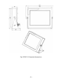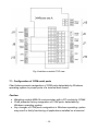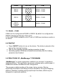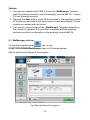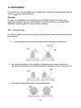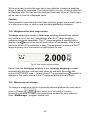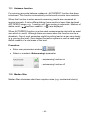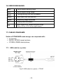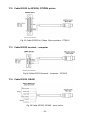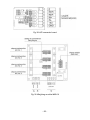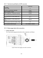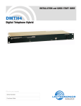
1
Service manual
Weighing terminal
PUE 5.15
PUE 5.19
For cooperation with strain gauge load cells
Manual number:
ITKU-84-02-10-13-PL
M ANUFACTURER OF ELECTRONIC
WEIGHING EQUIPMENT
RADWAG Wagi Elektroniczne, 26 – 600 Radom, Bracka 28, POLAND
Phone: +48 (0-48) 38 48 800, fax. +48 (0-48) 385 00 10
Sales department: +48 (0-48) 366 80 06
[email protected]
www.radwag.com
OCTOBER 2013
-2-
Table OF CONTENTS
1. INTENDED USE ................................................................................................................. 5
2. PRECAUTIONS MEASURES ............................................................................................. 5
3. WARRANTY CONDITIONS ................................................................................................ 6
4. UNPACKING AND INSTALLATION ................................................................................... 6
5. TERMINAL CONSTRUCTION ............................................................................................ 7
5.1. Overall dimensions ...................................................................................................... 7
5.2. Description of ports ..................................................................................................... 9
6. WEIGHING MODULE MW-04 ...........................................................................................11
7. INTERFACES MODULE ....................................................................................................11
7.1. Configuration of COM serial ports ...............................................................................12
7.2. RS485 – COM2 ..........................................................................................................13
8. STARTUP ..........................................................................................................................13
9. STRUCTURE OF „MwManager” PROGMAM ..................................................................13
9.1. MwManager start-up ...................................................................................................14
9.2. Parameters edition .....................................................................................................15
9.3. Weighment display .....................................................................................................17
9.4. Application settings ....................................................................................................18
9.4.1. Connection settings ...........................................................................................18
9.4.2. Language...........................................................................................................21
9.4.3. Other .................................................................................................................22
9.5. Parameters .................................................................................................................23
9.5.1. User parameters ................................................................................................23
9.5.2. Communication settings ....................................................................................24
9.5.3. INPUT/OUTPUT functions. ................................................................................26
9.5.4. Available platforms preview ...............................................................................28
9.5.5. Available A/D converters preview.......................................................................29
9.6. Functions....................................................................................................................30
9.6.1. Dosing ...............................................................................................................30
9.6.2. Checkweighing ..................................................................................................34
9.6.3. Input/Output state ..............................................................................................35
10. WEIGHMENT ..................................................................................................................36
10.1. Terms of use ............................................................................................................36
10.2. Scales zeroing .........................................................................................................37
10.3. Taring ......................................................................................................................37
10.4. Weighment for dual range scales .............................................................................38
10.5. Measuring unit change .............................................................................................38
11. SCALES PARAMETERS .................................................................................................39
11.1. Autozero function .....................................................................................................40
11.2. Median filter .............................................................................................................40
11.3. Filter.........................................................................................................................41
12. CHECKWEIGHING ..........................................................................................................42
12.1. LO threshold ............................................................................................................42
12.2. MIN/MAX threshold ..................................................................................................43
13. DOSING...........................................................................................................................44
14. PARAMETERS SAVED TO FILE .....................................................................................46
14.1. Save to file ...............................................................................................................47
14.2. Read from file ..........................................................................................................48
15. OFFLINE MODE ..............................................................................................................49
-3-
16. ERROR MESSAGES .......................................................................................................52
17. CABLES DIAGRAMS ......................................................................................................52
17.1. USB cable for a printer .............................................................................................52
17.2. Cable RS232 for EPSON, CITIZEN printer ..............................................................53
17.3. Cable RS232 terminal – computer ...........................................................................53
17.4. Cable RS232, RS485 ...............................................................................................53
17.5. Ethernet cable ..........................................................................................................54
18. EXTRA MODULES SPECIFICATION ..............................................................................54
18.1. A/D converter ...........................................................................................................54
18.1.1. Technical specification of A/D converter ..........................................................56
18.1.2. Strain gauge load cells connection ..................................................................56
18.2. 4 inputs / 4 outputs module ......................................................................................59
18.2.1. Technical parameters of 4IN/4OUT module ....................................................59
18.2.2. Input/output schematic diagram ......................................................................60
18.2.3. 4IN/4OUT in sockets .......................................................................................60
18.2.4. 4IN/4OUT through cable gland ........................................................................60
18.3. Profibus ...................................................................................................................61
19. TECHNICAL PARAMETERS ...........................................................................................63
20. EXTRA EQUIPMENT .......................................................................................................64
-4-
1. INTENDED USE
PUE 5.15, PUE 5.19 terminals are designed for scales that work with strain
gauge load cells. The terminals’ housing is made of stainless steel. PUE
5.15, PUE 5.19 are intended to be used in industry.
A big colourful screen of the terminal with a touch panel makes the software
operation much more comfortable since there is no need to use a keyboard.
PUE 5 terminal is a genuine device that consists of two units: the computer
and the weighing module, placed in one housing. Both of these units are
connected via an internal interface. The possibility of using common
operating systems allows external companies to create its software or to use
the existing one.
Such common devices as PC computers can be used with the terminal,
which is a great advantage while creating a network. Individual workstation
with the PC device is as well possible.
The terminal can work with 4 weighing platforms (option).
2. PRECAUTIONS MEASURES
A. Before the first use read the Service Manual carefully and follow the
instructions. Use the device as intended.
B. The weighed products should be placed in the central part of a scales
pan.
C. Do not use any means causing corrosion for cleaning.
D. The gross mass of weighed products must be lower than the scales
maximum load.
E. Great loads shouldn’t be left on the scales pan too long.
F. In case of a failure the device power supply should be instantly switched
off.
G. If the device is to be put out of operation it must be utilized in
accordance with the actual law regulations.
-5-
3. WARRANTY CONDITIONS
A. RADWAG company will repair or replace the elements that turn out to
be faulty in terms of production or construction.
B. Agreeing on the ways of any defects elimination in case of their unclear
origin can be done only in presence of the producer and the user
representatives.
C. RADWAG is not responsible for any loss or damages in case of
unauthorized or incorrect execution of production or service processes.
D. Warranty does not cover:
• Mechanical defects caused by product exploitation other than
intended, defects of thermal and chemical origin, defects caused by
lightning, overvoltage in the power network or other random event,
• maintenance (the cleaning process).
E. Loss of warranty takes place if:
• A repair is carried out outside RADWAG sales office or authorized
service point,
• Service claims intrusion into mechanical or electronic construction
by unauthorized people,
• The device does not bear company’s protective stickers.
F. Detailed warranty conditions are listed on a service card.
G. Authorized Service phone number:
(0-48) 384 88 00 extension numbers: 106 and 107.
4. UNPACKING AND INSTALLATION
A. Take terminal out of its factory packaging.
B. Connect the terminal to a weighing platform and place it on a smooth,
even, thick surface away from any heat sources,
C. It is necessary to level scales. Turn right and left the levelling feet. The
correct levelling is obtained when an air bubble is placed in a centre of
the small ring.
-6-
5. TERMINAL CONSTRUCTION
5.1. Overall dimensions
Fig.1 PUE 5.15 terminal dimensions
-7-
Fig.2 PUE 5.19 terminal dimensions
-8-
5.2. Description of ports
Fig.3 Back board view of PUE 5.15, PUE 5.19
1
2
3
4
5
6
7
8
9
10
11
12
13
Cable gland of the strain gauge load cell (x4items)
USB M12 4 pin port
RS232 port
4WY port (option)
Cable gland for the cable RS485 (option)
Panel USB port
Panel USB port
RJ45 ethernet port
USB M12 4 pin port
RS232, RS485 or 2xPROFIBUS (IN, OUT) port
4WE port (option)
Power supply cable gland
ON/OFF power switch-key
-9-
• Standard version ports:
-
Power supply cable: through PG7 cable gland,
Weighing platform cable: through PG11 cable gland,
RS232, RS485: M12 8pin ports,
Ethernet: RJ45 port,
USBx2: M12 4pin port,
USBx2: type A panel port
• Depending on the version of the terminal PUE 5.15, PUE 5.19 it is
possible to optionally equip it with the following ports:
-
Extra weighing platforms
Ethernet cable through the PG9 cable gland
Cable RS485 through the PG9 cable gland
4WE/4WY cable through the PG9 cable gland
4 IN/4OUT in M12 5 pin connector
Profibus communication module
• Ports typology
RS232, RS485
Pin1 – B (RS485)
Pin2 – RxD
Pin3 – TxD
Pin4 – A (RS485)
Pin5 – GND
Pin6 - +5VDC
Pin7 – NC
Pin8 – NC
PROFIBUS IN
(male)
Pin1 – NC
Pin2 – A
Pin3 – NC
Pin4 – B
Pin5 – NC
PROFIBUS OUT
(female)
RS232
Pin1 - +5V
Pin2 – A
Pin3 – GND
Pin4 – B
Pin5 – NC
Pin1 – NC
Pin2 – RxD
Pin3 – TxD
Pin4 – NC
Pin5 – GND
Pin6 - +5VDC
- 10 -
Pin1 – Vcc
Pin2 – DPin3 – D+
Pin4 – GND
USB
Ethernet
RJ45
USB panel
USB A
4WE
4WY
Standard RJ45
Standard USB A
Pin1-WE1
Pin2-WE2
Pin3-WE3
Pin4-WE4
Pin5-COMM
Pin6-+24VDC
Pin7-GND
Pin1-WY1
Pin2-WY2
Pin3-WY3
Pin4-WY4
Pin5-COMM
Pin6-+24VDC
Pin7-GND
Caution:
Depending on how many extra modules have been installed the number of
ports and cable glands and their position may change.
6. WEIGHING MODULE MW-04
PUE 5 weighing terminal is equipped with weighing module MW-04. It can
serve as a fully functional scales without a screen. Its parameters are kept in
a permanent storage of the module. It communicates with an internal PC
module via RS232 (COM6) interface.
„MwManager” program serves to maintain weighing module MW-04. Its
description is to be found further down this User Manual.
7. INTERFACES MODULE
Interfaces module allows connection of terminal ports and sockets that are
available on its back board. Weighing module MW-04 – RS232 (COM6) is
also connected to the Interfaces module.
- 11 -
Fig.4 Interfaces module TOP view
7.1. Configuration of COM serial ports
Chart below presents assignation of COM ports detectable by Windows
operating system to proper ports of a terminal back board.
Caution:
• Weighing module MW-04 communicates with a PC module by COM6
• Chart presents factory assignation of COM ports, detectable by
Windows operating system
• Any changes of COM ports assignation in Windows operating system
may result in faulty functioning of applications installed on a terminal.
- 12 -
Socket
Pins view
COM
RS232
RS485
RS232 – COM3
RS485 – COM2
RS232
RS232 – COM5
MW-04 module
(J6 on
334Rxxxx
board)
RS232 – COM6
7.2. RS485 – COM2
COM2 can be configured as RS485 or RS232. By defult it is configured as
RS485 (standard positioning of the ports).
In this case COM2 available on the J7 port of 344Rxxxx interfaces module is
not active.
8. STARTUP
• Press ON/OFF button to turn on the device. The button is placed at the
back of the terminal housing.
• Wait for the operating system loading procedure to start.
• Operating system Windows activates automatically after the loading
procedure has finished.
9. STRUCTURE OF „MwManager” PROGMAM
„MwManager” is a basic application installed on a terminal. It operates a
weighing module. This application serves as a display and a control panel. It
enables the scales maintenance and configuration.
The program enables reading of the mass, taring, zeroing, filtering,
input/output simulation and dosing function simulation for a given weighing
platform. Besides it enables setting input/output functions, which may be
assigned to a particular platform.
- 13 -
Caution:
1. The manual complies with 1.0.3.1 version of „MwManager” program
(and the following versions) and with weighing module MW-04 – version
1.1 and following versions.
2. Pressing the Save button saves all the changes in the weighing module.
All temporary parameters that haven’t been saved permanently into the
module are marked with red colour.
3. The view of some windows of the „MwManeger” program depends on
the number of operated A/D converter connected with the weighing
platforms and their configuration in the weighing module MW-04.
9.1. MwManager start-up
icon, or use
To start the program press
START/PROGRAMS/MwManager menu of Windows system.
Wait to see a main window of the program.
Fig.5 Main window of the program
- 14 -
9.2. Parameters edition
Parameters edition depends on a parameter type, to do it:
• Press
button and choose a demanded menu out of a list.
• Click a window of a given parameter
program keyboard to write a value.
and use a
• Press a button responsible for decrease
its increase
• Press
unselect it.
,
of a parameter value or
.
button to select a given option, press
- 15 -
button to
Functions of the key buttons:
-
Confirmation of a change of a parameter
-
Canceling change of a parameter
-
Scrolling the list of available parameter values up
-
Scrolling the list of available parameter values down
-
Information button, displays information about settings of a
given parameter
Saving the settings:
Changes will be stored in a weighing module after Save button
has been pressed. All temporary parameters that haven’t been saved
permanently will be marked with a red colour.
Procedure:
• Press Save button
,
• When you see a following message press <YES>
- 16 -
• You will see the confirmation message:
• Press <OK>,
• Changes have been saved in a permanent storage of a weighing
module.
If any setting changes will be done but not saved the user may press
Refresh button
to view the present settings.
9.3. Weighment display
Fig.6 Weighment display view
Symbols:
- exact zero
- stable measurement result
- 17 -
- weighing unit
- weighing platform number
Functions of the key buttons:
-
Zeroing
-
Taring
-
Selection of a weighing platform (when a module works
with more than one platform). Green colour indicates the
presently operated platform.
Caution:
Zeroing and taring function is available for a presently operated platform.
9.4. Application settings
Application settings bookmark contains: settings of connection with a
weighing module, list of available program interface languages and other
options
.
9.4.1. Connection settings
Connection settings
bookmark
module.
button, located in application settings
, starts settings of connection with a weighing
- 18 -
Fig.7 Connection settings window
Press MW-04 button
to connect to module MW-04. This button
is located in a “device selection” bookmark.
Description:
Device selection
The device to which the user wants to connect
weighing module MW-01
weighing module MW-04
To be selected in case of cooperation with weighing module MW-04
- 19 -
Connection types
Selection of interface connection with a weighing module
RS 232
Connection via RS232 port
TCP/IP
Connection via Ethernet network
RS 485
Connection for RS 485 network
Offline
Offline mode is used for saving and edition of all indispensable
parameters. Saving and edition is carried out in a configuration file.
RS232:
Port
Choice of COM port number to which the module is physically connected
Speed
Transmission speed of RS232 communication port
By default 57600 bps
Parity
Parity state. By default „none” (not editable value)
Data bits
Number of data bits. By default 8 data bits (not editable value)
Stop bits
Number of stop bits. By default 1 stop bit (not editable value)
TCP/IP:
IP address
Device IP address, by default 192.168.0.2
Port
Port set in the weighing module, by default 4001
RS485:
Port
Choice of COM port number to which a module is physically connected
Speed
Transmission speed of RS485 communication port
By default 57600 bps
Parity
Parity state. By default „none” (not editable value)
Data bits
Number of data bits. By default 8 data bits (not editable value)
Stop bits
Number of stop bits. By default 1 stop bit (not editable value)
Address
Weighing module IP address
Caution:
1. Weighing module MW-04 used in PUE 5 terminal communicates with an
internal PC module of the terminal via RS232 interface of COM6 port,
with the default transmission speed of 57600 bit per second.
2. Parameters <Connection settings> are not active in case of connection
with the weighing module.
- 20 -
Description of buttons:
Connecting with a module. After the connection has been
established the button function switches from “Connect” to “Disconnect”
and its colour changes from red to green.
Disconecting from a module. In case of accidental
disconnection the button’s function switches to „Connect” and the colour
changes to red again.
Closing „MwManager” application.
9.4.2. Language
Language button
bookmark
, which is located in application settings
, opens the window of language settings.
Fig.8 Language settings window
After selection of a language version press Apply button
in
order to save changes. Present version of the program offers following
languages:
• English
• Polish
- 21 -
9.4.3. Other
Other button
bookmark
, which is located in application settings
, lets to operate other available options.
Fig.9 Other options window
„Carry out a test connection during the application starting procedure”
– this option enables the program to automatically connect with the weighing
module. It connects either by its default type of connection or the recently
chosen one.
„Turn on a touch interface” – this option adapts a visual image of
”MwManager” program to make it able to work with PUE5 weighing
terminal, it turns on a touch panel and it turns off a mouse.
- 22 -
After setting the options press Save button
introduced changes.
in order to save
9.5. Parameters
Parameters bookmark
contains user parameters, weighing
module communication parameters, INPUT/OUTPUT functions and a
preview of available scales platforms and A/D converters.
9.5.1. User parameters
User parameters button
, which is located in Parameters
opens a user parameters window. These
bookmark
parameters are an active platform parameters, they can be edited by each of
the users.
Fig.10 User parameters window
List of user parameters:
Autozeroing
-
Turning on/off autozeroing function
- 23 -
Beep
-
Median filter
-
Filter
-
Current unit
-
Sound signal (unavailable for MW-04 module)
Median filter value settings
None – median filter turned off
The moving average filter speed settings
None – filter turned off
Change of a current unit
Caution:
When few platforms are being operated by MW-04 module at one time, only
parameters for a selected platform are displayed and can be edited .
9.5.2. Communication settings
Communication button
, which is located in Parameters
opens a weighing module parameters window.
bookmark
These parameters can be viewed and edited by each of the users who
connect to the weighing module.
• Ethernet
- 24 -
Fig.11 Ethernet communication parameters window
Description of fields:
IP address
-
Device IP address, by default 192.168.0.2
Subnet mask
-
Ethernet subnet mask, by default 255.255.255.0
Default gateway
-
Ethernet default gateway, by default 192.168.0.1
Port
-
TCP communication port, by default 4001.
-
Number of seconds of the device inactivity that results in
disconnection of the device, number of seconds ranges
from 0 to 300 [s].
Timeout
• RS 232/485
Fig.12 RS communication parameters window
Description of fields:
Module address
-
Weighing module address on RS485 network (a separate IP
address is given to each of the network devices), default value
is 1. Values range from 1 to 254.
Speed RS232
-
RS232 communication interface speed transmission. By default
57600 bps
- 25 -
Speed RS485
-
RS485 communication interface speed transmission. By default
57600 bps
To save changes of communication parameters it is necessary to execute
restaring procedure of a weighing module.
One must remember that new parameters have to be written in the
Connection settings window. See point 9.4.1 of this manual.
Caution:
Internal weighing module MW- 04 used in the PUE5 terminal is physically
connected to the PC module of the terminal via RS232 interface of COM6
port and it works with a default transmission speed of 57600 bps.
9.5.3. INPUT/OUTPUT functions.
Weighing module MW-04 can have up to 4 inputs and 4 outputs.
INPUT/OUTPUT button
, which is located in Parameters
opens a window allowing the user for configuration
bookmark
of weighing module Inputs and Outputs. Select number of scales/platform for
which the function is to be realized.
- 26 -
Fig. 13 Inputs/Outputs configuration window
- 27 -
•
Inputs configuration
Inputs functions:
None
Inactive Input
Taring
Selected platform taring
Zeroing
Selected platform zeroing
Dosing Start
Start of a dosing process for a selected platform
Dosing Stop
Stop of a dosing process for a selected platform
• Oututs configuration
Outputs functions:
None
Stable
Stable MIN
MIN
Stable OK
stabilny
OK
Stable MAX
MAX
Inactive Output
Stable weighing result over the LO mass, on a selected
platform
Stable weighing result over LO mass and below MIN
threshold, for a selected platform
Unstable weighing result over LO mass and below MIN
threshold, for a selected platform
Stable weighing result between MIN and MAX
thresholds, for a selected platform
Unstable weighing result between MIN and MAX
thresholds, for a the selected platform
Stable weighing result over MAX threshold, for a
selected platform
Unstable weighing result over MAX threshold, for a
selected platform
Caution:
If the user sets a function for a given Output and if at the same time on this
Output a function of fast dosing or fine dosing is set then upon start of
a dosing and during its duration the outputs will be activated according to
dosing parameters settings. After the process has finished the set functions
will swap to Output.
9.5.4. Available platforms preview
- 28 -
The button
, which is located in Parameters bookmark
opens scales windows preview of all the scales being operated
by MW-04 module. For each platform the following information is displayed:
A/D converter(s) divisions, calibration coefficient and an input mass.
Caution:
Window preview depends on the number of A/D converters, the number of
platforms connected to the device and their configuration.
Fig.14 Example of 4 weighing platforms preview window
9.5.5. Available A/D converters preview
ADC button
, which is located in Parameters bookmark
opens a preview of reading units, calibration coefficient, mass,
correction coefficient and input mass of the available A/D converters.
- 29 -
Caution:
Window preview depends on the number of A/D converters, the number of
platforms connected to the device and their configuration.
Fig.15 A/D converter divisions preview window
9.6. Functions
Dosing, checkweighing, state and Input/Output simulations are set in
functions bookmark
.
9.6.1. Dosing
Dosing button
, which is located in Functions bookmark
opens a windows with settings for a dosing
process of a weighing platform (presently selected one).
- 30 -
Fig.16 Dosing parameters window
• Bargraph
Dosing window contains a graphic bar that visualizes mass readout
within a weighing range of a weighing module.
Bargraph can be graduated upto 120% of an extreme dosing threshold if
a fine dosing threshold option has been selected. If a fine dosing
threshold option is turned off then the bargraph is graduated in
accordance with a fast dosing threshold.
Fig.17 Graduation of bargraph for a fast dosing threshold
- 31 -
Fig.18 Graduation of bargraph for a quick and fine dosing threshold
Fig.19 Bargraph for a small amount of mass with a graduation option turned off
Fig.20 Bargraph for the same amount of mass with a graduation option turned on
• Dosing parameters
Fig.21 Dosing parameters settings window
Depending on the need dosing process may be carried out in two stages or
one stage.
- 32 -
Fields description:
Fast dosing threshold
Output number
st
Mass value which finishes the 1 stage
of a dosing process.
(switching on to the second stage, not in
case of one-stage dosing process.)
Choice of an output or few outputs
st
active during the 1 dosing process
stage (for a presently operated
weighing platform).
Fine dosing threshold
Output number
nd
Mass value which finishes the 2 stage
of a dosing process.
(the end of the dosing process.)
•
Choice of an output or few outputs
st
active during the 1 dosing process
stage (for a presently operated
weighing platform).
Dosing parameters
Dosing status window informs about a
present state of a dosing process on a
given weighing platform.
Description:
Dosing status
Dosing process state:
DOZING – dosing in progress
SUSPENDED – suspending the dosing process.
STOPPED – stopping the dosing process,
FINISHED – dosing is finished.
• Inputs simulation
Inputs simulation allows for simulation of an operation of a function
assigned to a particular Input. See point 9.5.3 of this manual.
Przycisk funkcji, przypisanej do wejścia 1
Przycisk funkcji, przypisanej do wejścia 2
Przycisk funkcji, przypisanej do wejścia 3
Przycisk funkcji, przypisanej do wejścia 4
- 33 -
• Dosing simulation
There are Stop dosing and Start dosing buttons in the bottom part of a
dosing simulation window. No matter what functions have been assigned
on Inputs, these buttons enable dosing process start and stop.
9.6.2. Checkweighing
Turning on
option and pressing
button opens
checkweighing settings window for a presently selected weighing platform.
Fig.22 Checkweighing parameters window
Description of the fields:
LO
threshold
Min
threshold
Max
threshold
Gross value of mass, checkweighing function is active if this
value is exceeded
Mass value for estimation of tolerance threshold.
- MIN threshold value is signaled below the Min threshold
value
- OK threshold is signaled between Min threshold - Max
threshold values.
- MAX threshold value is signaled over the Max threshold
value
Functions signalling within thresholds:
- 34 -
MIN
OK
MAX
Caution:
Checkweighing signalling is available after the Output functions have been
set. See point 9.5.3 of this manual.
9.6.3. Input/Output state
Window of Inputs signaling which also allows configuration of Outputs state
option and pressing
opens upon activation of functions
Input/Output state
button.
Fig.23 Inputs/Outputs states window
Input/output numbers in program accord with the numeration in a module.
Active input/output
Inactive input/output
Simulation of output operation is possible after this output number has been
pressed. This very output activates immediately if only no other function has
been assigned to it.
Output activity simulation is available in a dosing window.
- 35 -
10. WEIGHMENT
Put a product to be weighted on a scales pan. Read a measurement when a
has been displayed.
marker
Caution:
In case of cooperation of weighing module MW-04 with more than one
weighing platform the user must select a correct platform in a weighment
display in order to get the correct mass reading.
10.1. Terms of use
In order to assure long device usage and accurate mass measurements the
user should:
•
avoid applying mechanical shocks while loading a scales pan:
• put loads precisely in the centre of a scales pan (erros of eccentric
weighment are defined by PN-EN 45501 standard, point 3.5 and 3.6.2):
• not load a scales pan with concentrated force:
- 36 -
• avoid side loads, especially side shocks:
10.2. Scales zeroing
In order to zero mass readout of a presently selected platform the user has
button which is to be found in a weighment display of a
to press
„MwManager” program (the top right hand corner) or he has to initiate
zeroing function defined for a given input (See point 9.5.3 of this manual).
On a display mass readout with zero value will be shown next to symbols:
and
.
Zeroing means estimating a new zero point which will be recognized by scale
as an exact zero. Zeroing is possible only when display states are stable.
Caution:
Zeroing a display state is possible only within the range upto ±2% of the
maximum scales load. If zeroing value is greater than ±2% of the maximum
load then the message Err2 is displayed.
10.3. Taring
To estimate net mass for a presently selected platform the user needs to put
packaging on a device and wait for a readout to stabilize, next (s)he may
. The other possibility is to initiate tare function defined
press button
for a given input (See point 9.5.3 of this manual).
On a display mass readout with zero value is be shown next to symbols : Net
. The scales has been tared.
i
- 37 -
While using tare function the user has to pay attention to maximal weighing
range. It cannot be exceeded. The readout which is a sum of tarred mass will
be displayed after the load and the package have been taken off. Minus sign
will be seen in front of a displayed value.
Caution:
Taring process cannot be executed when a display shows minus mass value
or a zero mass value. In such a case the message Err3 is displayed.
10.4. Weighment for dual range scales
1st range weighing proceeds to 2nd range weighing automatically without
st
any interference of the user (immediately after the 1 range weighing
nd
maximum has been exceeded). The 2 range weighing is signaled with a
display of a
sign in the top left hand corner of the display. After a load
nd
has been taken off the indication is zero. The weighment accuracy is the 2
range accuracy up to the moment of getting back to zero.
Fig.24 2nd range scales window
Return from the 2nd range weighing to the 1st range weighing proceeds
automatically after the load has been taken off and after the scales has
nd
symbol is
entered AUTOZERO zone – instead of the 2 range weighing
st
displayed. The scale returns to the 1 range weighing accuracy mode.
10.5. Measuring unit change
To change a measuring unit for a presently selected platform the user has to
button, which is to be found in in users
press a Change
parameters window. To open user parameters window the user needs to
open „MwManager” program window first.
- 38 -
Fig. 25 User parameters window
Possible choices:
• When a main unit of scales is [kg], the user can select following units:
[kg, lb, oz, ct, N, g], for verified scales [lb, oz, N] are unavailable;
• When a main unit of scales is [g], the user can select following units: [g,
kg, lb, oz, ct, N], for verified scales [lb, oz, N] are unavailable;
11. SCALES PARAMETERS
The user can adapt scale to an outdoor environmental conditions (filters
order) or his own needs (active autozero)
These parameters are to be found in parameters bookmark
. They are available for each of the platforms, and for each of
the platforms they can be edited.
List of parameters:
•
•
•
Autozeroing,
Median filter,
Filter.
- 39 -
>
11.1. Autozero function
For ensuring accurate balance readaouts „AUTOZERO” function has been
introduced. This function automatically controls and corrects zero readouts.
When this function is active several measuring results are compared at
regular intervals. If value differentiating these results is lower than declared
AUTOZERO range, e.g. 1 reading unit, than zeroing is automatic. Markers of
and zero readout are displayed.
stable result When AUTOZERO function is active each measurements start with an exact
zero which is useful. Although there are cases when this function can be a
drawback. One of such examples might be putting load on a pan very slowly
(e.g. pouring the load). Zero readout correction system in such a case might
distort readout of a real mass of the load.
Procedure:
,
• Enter user parameters window
• Select or unselect <Autozeroing> parameter
- autozeroing function on
- autozeroing function off
11.2. Median filter
Median filter eliminates short-term impulse noise (e.g. mechanical shock).
- 40 -
Procedure:
• Enter user parameters window
• Select <Median filter> parameter, press
• Select a desired setting out of the available list
Available parameters:
None - medain filter turned on
0.5, 1, 1.5, 2, 2.5 - medain filter turned off
11.3. Filter
Moving average filter adjusts scales to outdoor environmental conditions.
Procedure:
• Enter user parameters window
• Select <Filter> parameter, press
• Select a desired setting out of the available list
Available parameters:
none, very fast, fast, medium, slow
Caution:
The higher the order of a filter is the longer time of measurement stabilization
it needs.
- 41 -
12. CHECKWEIGHING
Checkweighing is a function that enables precise weighment of a sample for
which minimum and maximum weighing threshold, so called checkweighing
thresholds, have been determined (LO – to little mass of the sample, HI – to
big mass of the sample, OK – correct mass of the sample).
These states are presented through light signaling or through steering of
peripheral devices systems.
>0<
Lo
MIN
Próg Min
OK
Próg Max
MAX
Fig.26 States range for checkweighing function
Caution:
Starting procedure of checkweighing function and its signaling have been
presented in point 9.6.2 of this manual.
12.1. LO threshold
<LO threshold> parameter detemines net mass upon exceeding which the
checkweighing function activates.
Procedure:
• Click parameter window:
• Enter LO threshold value.
- 42 -
HI
• Press
button to close dialog window
• Press Save
button to save introduced changes into a
permanent storage of a module.
12.2. MIN/MAX threshold
<MIN threshold> parameter determines net mass threshold of a
checkweighing function. For the determined net mass the state swaps
between Min and OK.
<MAX threshold> parameter determines net mass threshold of
checkweighing function. For the determined net mass the state swaps
between OK and MAX.
Outputs signaling starts over the set net LO threshold value.
Procedure:
• Click <Min threshold> parameter window or <Max threshold>
parameter window,
• Enter a threshold value
- 43 -
• Press
button to close a dialog window,
• Press Save
button to save introduced changes into a
permanent storage of a module.
13. DOSING
Dosing function enables precise weighment of a given
product up to desired value.
<Fast dosing threshold> parameter stands for net mass value of fast
(rough) dosing below which one or more outputs are active. (Outputs are
assigned to fast dosing).
<Fine dosing threshold> parameter stands for net mass value of slow
dosing below which (but at the same time not below mass value of fast
dosing threshold) one or more outputs are active. (Outputs are assigned to
fine dosing).
Procedure:
• Click <Fast dosing threshold> parameter window or <Fine dosing
threshold> parameter window,
- 44 -
• Enter a threshold value
• Press
button to close the dialog window,
• Press Save
button to save introduced changes into a
permanent storage of a module.
• Changes will be confirmed with the following message:
• If any threshold values will be changed but not saved than present
settings can be read out, to do it the user has to use a Readout
button.
• Readout will be confirmed with a following message:
- 45 -
Caution:
Description of a dosing function and its parameters are to be found in the
point 9.6.1 of this manual.
14. PARAMETERS SAVED TO FILE
„MwManager” program allows saving set parameters into *.sav file format.
This function can be useful when saving module settings as a safety copy in
case of a weighing module breakdown. Parameters saved on a safety copy
can be used for further configuration purposes with a greater number of
weighing modules.
Fig.27 An example of a window with available options Save to file and Read from
file.
File format:
MW04_(factory number)_RRRR-MM-DD_HH-MM.sav
- 46 -
14.1. Save to file
Procedure:
•
•
Press Save to file
parameters have been set
button after the weighing module
In an operating system window select file destination folder and press
Save
button.
Fig.28 „Save as” system window
•
The following message will inform about correctly saved parameters.
- 47 -
Caution:
Preview of an operating system window depends on the installed operating
system therefore it may differ from the one presented in Fig.28.
14.2. Read from file
Procedure:
•
•
In order to read the parameters press Read from file button
Open operating system window, see Fig 29, and select a previously
button.
saved file, next press Open
Fig. 29 „Open” window
•
In Parameters groups selection window select Read all parameters
option or Read chosen parameters option and press <OK>.
- 48 -
Fig.30 Parameters groups selection window.
•
If parameters have been read correctly the following message will be
displayed:
15. OFFLINE MODE
Offline mode allows for operation of a selected options of a program without
the need of connecting it to a weighing module. Through this indispensable
parameters can be saved without a physical connection with the device.
- 49 -
Fig.31 Offline mode window preview.
Procedure:
•
button, which is to be found
Press Connection settings
bookmark
in Application settings
•
In Connection types settings window select Offline option
•
Press Connect
•
„Offline” message will be displayed on the scales screen.
button
- 50 -
•
Set chosen parameters and save the configuration to file, see
description in point 14.1.
- 51 -
16. ERROR MESSAGES
Err2
-
Value beyond zeroing range
Err3
-
Value beyond taring range
Err8
-
Tarring/zeroing time limit exceeded
NULL
-
Zero value from the load cell
FULL
-
Measuring range exceeded
HI
-
Display state exceeded
LH
-
Input mass error, readout beyond range
(from -5% to +15% of an input mass)
17. CABLES DIAGRAMS
Scales of STANDARD made design can cooperate with:
•
•
•
a computer,
KAFKA, EPSON receipt printers,
CITIZEN, ZEBRA label printers,
17.1. USB cable for a printer
Fig.32 USB cable for a printer - PT0087
- 52 -
17.2. Cable RS232 for EPSON, CITIZEN printer
Fig.33 Cable RS232 for Citizen, Epson printers - PT0019
17.3. Cable RS232 terminal – computer
Fig.34 Cable RS232 terminal – computer - PT0020
17.4. Cable RS232, RS485
Fig.36 Cable RS232, RS485 – wires colors
- 53 -
Caution:
These are colours for cables of “M12” standard. The figure shows just an
example cable type.
17.5. Ethernet cable
Fig.35 P0212 Ethernet cable
18. EXTRA MODULES SPECIFICATION
Scales with PUE5 terminal can optionally be expanded with an extra modules
positively influencing the device functionality:
•
•
•
Extra A/D converter module
4 Inputs / 4 outputs module
Profibus DP interface.
18.1. A/D converter
A/D converters influence PUE 5 terminal functionality. Additional weighing
modules can work with PUE 5 thanks to them. A/D converter board is fixed
onto weighing module MW-04, inside PUE 5 gauge. It is possible to fix up to
4 A/D converter boards. On a housing lid an additional cable gland is
installed through which load cell cable is led out. Parameters of all load cells
are identical.
- 54 -
Fig.38 A/D converter board
Fig.39 Weighing module MW-04
- 55 -
18.1.1. Technical specification of A/D converter
Maximal number of divisions from A/D
converter
8 388 608
OIML class
III
Number of verification intervals
6000e
Max increase of signal
19.5mV
Max voltage per 1 verification interval
3.25µV
Min voltage per 1 verification interval
0.4µV
Min impedance of strain gauge load
cells
80 Ω
Max impedance of strain gauge load
cells
1200 Ω
Strain gauge load cells feeding voltage
Strain gauge load cells type
5V
4 or 6 cables + screen
18.1.2. Strain gauge load cells connection
• 6-wire load cells
For 6-wire strain gauge load cells do the connection as follows:
Fig.40 6-wire strain gauge load cell connection
- 56 -
Interface on load
cell board
Strain gauge load
cell signal
Notes
E
SCREEN
REF+
REFIN+
IN+5V
AGND
SENSE +
SENSE OUTPUT+
OUTPUTINPUT+
INPUT-
See strain gauge load cell
connection rules
• 4-wire load cells
For 4-wire load cells do the connection as follows:
Connect REF+ with +5V and REF- with AGND using the LiY 0,34mm2
cable.
Fig.41 4-wire load cell connection
Interface on load
cell board
Strain gauge load
cell signal
E
SCREEN
REF+
REFIN+
IN+5V
AGND
OUTPUT+
OUTPUTINPUT+
INPUT-
- 57 -
Notes
See the strain gauge load cell
connection rules
Connect to +5V
Connect to AGND
• Strain gauge load cell screen connection rules.
While connecting signal cable screen of a strain gauge load cell the
following connection rules must be obeyed in order to ensure correct
weighment.
In both cases (scales platforms with 6-wire and 4-wire signal cable) the
same rule of connection is obligatory:
Permanent galvanic
connection of the screen
and the construction of the
scales arm, done by the
producer
No galvanic connection of
the screen and the
construction of the scales
arm
Scales with metal head
connected with platform via
signal cable
POINT B
POINT B
Compact mechanical
construction of scales (e.g.
Scales with head on a mast),
head in a metal housing.
POINT B
E
Point B – electrical connection with housing of a terminal (e.g. threaded
pin, threaded hole to be used for screwing of a soldering eye),
E – soldering point of A/D converter board
• Test of galvanic connection of a strain gauge load cell screen with
a platform construction
To carry out a test ohmmetter is needed.
- 58 -
18.2. 4 inputs / 4 outputs module
Fig.42 4Inputs/4Outputs module – description of cable outlets
4IN/4OUT module is installed inside a terminal on weighing module MW-04
board (Fig. 39).
Two optional versions are available:
•
•
4IN/4OUT fed on hermetic socket
4IN/4OUT fed through cable glands.
18.2.1. Technical parameters of 4IN/4OUT module
Input parameters
Inputs number
Inputs type
Max switching current
Max forward voltage
4
OptoMOS
0,2A DC
50V DC
Outputs parameters
Outputs number
Outputs type
Steering voltage range
4
Optoinsulated
5 -24V DC
- 59 -
18.2.2. Input/output schematic diagram
Inputs diagram
Outputs diagram
Fig.43 Input/output schematic (demonstrating) diagram
18.2.3. 4IN/4OUT in sockets
Configuration for an optional made design of a terminal.
Signals are fed on hermetic M12 8P sockets, one socket for inputs, the other
one for outputs.
Chart below presents signals distribution for each pin of a socket.
Pin1-IN1
Pin2-IN2
Pin3-IN3
Pin4-IN4
Pin5-COMM
Pin6-+24VDC
Pin7-GND
Pin1-OUT1
Pin2-OUT2
Pin3-OUT3
Pin4-OUT4
Pin5-COMM
Pin6-+24VDC
Pin7-GND
4IN
4OUT
18.2.4. 4IN/4OUT through cable gland
Configuration for an optional made design of a terminal.
Signals are fed on two cables, one cable for inputs, the other one for outputs.
Chart below presents signals distribution for each wire of a cable.
- 60 -
Cable for INPUTS
WIRE NUMBER
1
2
3
4
5
6
7
SIGNAL
IN1
IN2
IN3
IN4
COM
+24V
GND
Cable for OUTPUTS
WIRE NUMBER
1
2
3
4
5
6
7
SIGNAL
OUT1
OUT2
OUT3
OUT4
COM
+24V
GND
18.3. Profibus
Configuration for an optional made design of a terminal.
PROFIBUS module is installed on an interface board, inside PUE 5 gauge.
Signals are fed on hermetic M12 5P PROFIBUS IN, PROFIBUS OUT
sockets (type B ports coding - PROFIBUS)
Fig.44 Interfaces board with an installed PROFIBUS module.
- 61 -
Chart below presents signals distribution for each pin of a socket.
Pin1 – NC
Pin2 – A
Pin3 – NC
Pin4 – B
Pin5 – NC
PROFIBUS IN
(male)
Pin1 - +5V
Pin2 – A
Pin3 – GND
Pin4 – B
Pin5 – NC
PROFIBUS OUT
(female)
Caution:
For a correct work reconfiguration of jumpers on a PC module is required –
JP1 jumpers
Fig.45 Jumpers configuration on a PC module for PROFIBUS
- 62 -
19. TECHNICAL PARAMETERS
PUE 5.15
Housing
PUE 5.19
Stainless steel
IP rating (degree of protection)
Display
IP65
TFT 15’’÷15,6” IR
with touch panel
Power
TFT 19’’IR
with touch panel
100÷240VAC 50-60Hz
Work temperature: 0°C to +40°C
Storage temperature: -20°C to +60°C
Temperature range
Max number of load cell reading units
8 388 608
OIML class
III
Number of verification intervals
6000e
Max increase of signal
19.5mV
Max voltage per 1 verification interval
3.25µV
Min voltage per 1 verification interval
0.4µV
Min impedance of a strain gauge load
cell
Max impedance of a strain gauge load
cell
80 Ω
1200 Ω
Strain gauge load cells feeding voltage
5V
Strain gauge load cells type
Processor
4 or 6 cables + screen
Intel® Atom™ D525 Dual-Core 1.8 GHz
RAM
2 GB DDR3 800 MHz
Data storage
HDD SATA lub SSD SATA
Graphics storage
max. 224 MB
Ethernet
Standard interfaces
10/100/1000 Mbit
2xRS232, RS485, 4xUSB 2.0, Ethernet
Pofibus, or other communication
modules marked with the CE sign.
4 INputs, 4 OUTputs
Optional interfaces
Optional IN/WY
- 63 -
20. EXTRA EQUIPMENT
Extra A/D converter
-
Metrological parameters like in
the main platform
Inputs/Outputs module
-
Additional 4 inputs / 4 outputs
Profibus DP interface
-
Slave mode operation
- 64 -
MANUFACTURER
OF ELECTRONIC WEIGHING EGUIPMENT
RADWAG WAGI ELEKTRONICZNE
26 – 600 Radom, ul. Bracka 28
Phone: +48 48 38 48 800, fax. + 48 48 385 00 10
Sales department: + 48 48 366 80 06
e-mail: [email protected]
www.radwag.com
- 65 -