1
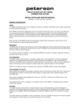
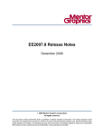
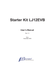
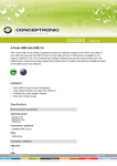
IRDA-WELDER 600W
User-manual
SMD_King, the Netherlands
IRDA-WELDER 600W
User-manual
INDEX
1. Features…………………………………………………………….2
2. Technical Parameters……………………………………………..2
3. Instrument Inventory……………………………………………2
4. Description of IR reworkstation components ……………….3
⑴ Main body……………………………………………………3
⑵ Front panel………………………………………………………4
⑶ Back panel………………………………………………………4
⑷ IR-lampholder ………………………………………………5
5. Steps of assembling………………………………………………6
⑴ Stand with IR-lampholder ……………………………………6
⑵ Rotation-ring ………………………………………………………6
⑶ Stand into base-unit………………………………………………6
⑷ Connecting powerline halogen IR-lamp ……………..…………6
6. Method of operation………………………………………………7
⑴ Starting……………………………………………………………7
⑵ IR-Rework…………………………………………………………8
⑶ IR-Soldering………………………………………………………8
⑷ 936 Soldering-iron………………………………………………8
7.Precautions…………………………………………………………9
1
IRDA-WELDER 600W
User-manual
Features
1. Gain access to sophisticated SMD-technology through IR welding.
2. Many advantages compared to a hot-air reflow-station, due to effective
and penetrating IR-waves.
3. This machine is easy to operate. Users will notice they can fully operate this
machine within 1 day.
4. This machine can rework printboards of several lengths, from 15 up to 45
cm.
5. The ceramic IR-heater, with the size of 120 x 60 mm and the halogen
IR-lamp, emit more than 550W of IR, straight to the surface of a printboard.
6. Using IR avoids airflows which might blow away components from
printboards and garantees an equal heatingpatern. This technology is
perfect to use for all kind of SMD-components, especially for Micro-BGA
components.
Technical parameters
Working voltage
AC220/110V - 50/60Hz
Output power
600W
Temperature
100 oC - 350 oC
Instrument inventory
Chassis
1
Stand
1
Rotation-ring
1
IR-body (IR-lamp + fan)
1
IR-Filter and cover
1
Preheat clamp
1
936 Soldering-iron
1
936 Soldering holder
1
Power cable
1
User manual
1
2
IRDA-WELDER 600W
User-manual
Description of IR reworkstation components
1) Main body
Cooling fan
Stand topcover
IR-lampholder
Stand
IR-Filter and cover
Focus-knob
936 soldering holder
Rotation-ring
936 soldering-iron
Ceramic IR-preheater
Chassis (working bench )
Preheat clamp
Front panel
3
IRDA-WELDER 600W
User-manual
2) Front panel
Buttons for temperature settings
Display for desired and
actual set temperature of
ceramic IR-pre-heater
Display for desired and
Display for desired and
actual temperature of
actual temperature of 936
IR-light
soldering-iron
ON/OFF-switch
ON/OFF-switch
ON/OFF-switch 936
IR pre-heater
halogen IR-lamp
soldering-iron
3) Back panel
Power inlet
Fuse
Powerconnector
Powerconnector 936
halogen IR-lamp
soldering -iron
Power source switch
4
IRDA-WELDER 600W
User-manual
4) IR-lampholder
Focus knob
Focus IR-lampholder
Focus IR-lampholder
Nut to fixate IR
lampholder to stand.
Rotation-ring-nut
5
IRDA-WELDER 600W
User-manual
Steps of assembling
1) Slide the stand in the IR-lampholder as indicated. Adjust the optimal height for the
IR-lampholder. Don’t fix the nut of the IR-lampholder yet.
Insert stand as indicated
Nut
Stand
2) Install the rotation-ring as indicated. At the required height you can fix the nut.
Rotation-ring
Slide the rotation-ring onto
the stand as indicated.
3) Insert the stand into the post of the base-unit. Rotate the stand clockwise in order to
attach it to the base-unit. After the stand is fixed into the base-unit, the nut of the
IR-lampholder can be fixed by rotating it clockwise.
Rotate the stand clockwise
into the post of the base-unit.
4) Connect the wire of the IR-lamp to the base-unit (chassis) at the backpanel. Tighten it,
by rotating it clockwise.
6
IRDA-WELDER 600W
User-manual
Method of operation
Adjustable IR-lens
Preheat clamp
(showing a fixated
demo-printboard)
Chassis (workingbench )
1) Starting
•
•
Insert the powercable into the poweroutlet (110 / 220 VAC).
Be sure to turn all switches off at the frontplane. After you are sure about this, turn
on the power source, by switching it on at the rear of the chassis (backplane). The
displays will show the last restored temperatures.
•
Fix the printboard you want to repair / solder into the pre-heat clamp. Use the
specific powerswitch for the device you want to heat up i.e. ceramic IR pre-heater,
halogen IR-lamp or the 936 solder-iron.
NOTE : Always keep a save distance between the hologen IR-lamp and the
ceramic IR-preheater, to avoid overheating of halogen IR-lamp, its lens and /
or body.
•
For using the IR lamp you can select a temperature-range of 60 oC up to 350 oC.
The following given values are indicators :
o
An area of approx. 15x15 mm : 240-300 C
o
An area of approx. 25x25mm : 300-350 C.
The light emits straight to the surface of the printboard and can reach a
-
o
•
•
temperature of 350 C. Please take personal precaution, like protecting your
eyes and skin-tissue, in order to avoid severe damage. Always use the IR-filter,
when you are IR-soldering
By focussing the lens, you can modify the size of IR-lightspot. The minimum
diameter of the beam / spotsize is 15mm. The max. diameter of the beam is 30mm.
Advice : Use a diameter between 20 to 30 mm.
Activate the required devices (IR preheater, IR-lamp or solder-iron) by turning on
the respective powerknob(s) on. Wait until the display shows the desired
temperature.
IMPORTANT NOTE : When halogen IR-lamp is activated, always use IR-filter or use
IR-protective goggles.
7
IRDA-WELDER 600W
User-manual
2) IR-rework.
•
Fix the printboard into the preheat clamp and
place it above the ceramic pre-heater. Make
sure the IR-beam of the halogen IR-lamp is
focussed at the desired component(s).
•
Just wait until the printboard is heated enough
and the solder becomes fluid or untill the
SMD-component can be removed with almost
zero force.
3) IR-soldering
• Clean pad with IPA (Iso Propane Alcohol) and apply
a minimum of solder flux.
If soldering non-BGA-components (SOC / SOIC /
PLCC / etc) : apply solderpaste
•
BGA without solderballs attached : place solderballs
and heat the specific area untill the solderballs
change surface.
NOTE : this requires some experience
•
1) BGA-component without solderballs attached :
Place BGA-component carefully.
2) BGA-component with solderballs : Wait until flux
melted and position the BGA-component carefully.
NOTE : A pair of tweezers might be a welcome
support for positioning the BGA.
3) Other SMD-components : Position
SMD-component
•
Wait until component is soldered to the print. Remove preheat clamp with printboard
and wait untill heated surface has reached roomtemperature. Check bondings if
everything is properly attached / soldered. NOTE : This requires some experience.
4) 936 soldering
•
Select required temperature and solder component(s) at desired temperature.
8
IRDA-WELDER 600W
User-manual
Precautions
•
After finishing IR-soldering (IR preheater and / or halogen IR-lamp) only shut down the
respective switch at the frontpanel.
NEVER shut down the mains powerswitch at the rearpanel, untill the
IR-elements (IR preheater and / or halogen IR-lamp) are at roomtemperature
•
Never inhale the fume / smoke / gas which comes from solder flux or solder. This is
toxic ! Use a blower, or a vacuumcleaning blower provided with active carbon. Also try
to avoid to get the lens / body in contact with this fume / smoke / gas.
•
•
Never operate this machine in humidious areas, to avoid the risk of shortcut.
Do not operate this machine in a too dry area, to avoid static electricity, which might
damage internal electronics or your SMD-components.
•
Be sure this machine and you are connected to the same ground, in order to avoid the
risk of static electricity.
•
Disconnect the mains powerplug when the reworkstation will not be used for more than
24 hours.
•
•
Never open this machine for repair or other purposes.
Operate carefully and take care.
9