1
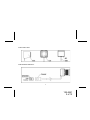
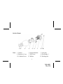
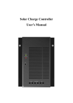
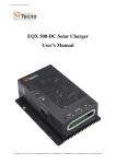
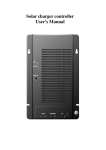
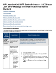
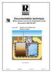
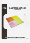
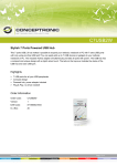
Installation Instructions
Model CCDF
Color Camera External Mount
CCDF FEATURES:
l
High Resolution, 1/3”CCD Color Camera
l
Compact Zinc Alloy Die Cast Body
l
Waterproof Housing
l
Waterproof Microphone
l
Adjustable Mounting Angle
l
Wide Angle Lens
l
Flush Mount or Surface Mount
128-6951
1 of 12
Color Camera View:
Cable Connector End View:
1
128-6951
2 of 12
Specifications:
1. Signal System: NTSC
2. Voltage: DC12V
3. Current: 80mA
4. Image Sensor: 1/3” CCD Color Sensor
NTSC: 510 X 492 picture elements
5. Horizontal Definition: 420 Lines
6. Viewing Angle: 120 degrees
7. Minimum Illumination: 0.8 LUX
8. Outer Dimensions: 1.18”(W) x 1.10”(H) x 1.65”(D)
9. Weight: 2.5 Oz
2
128-6951
3 of 12
Contents:
3
128-6951
4 of 12
Contents Description:
1. Camera: 1
2. Support Bracket: 1
3. Lock Nut: 1
4. Protective Cover: 1
5. Top Cover: 1
6. Flat Washer 1: 1
7. Flat Washer 2: 1
8. Slant Washer 1: 1
9. Slant Washer 2: 1
10. Tapping Screw: 2
11. Combine Screw: 2
12. Washer: 2
13. Docking Nut: 2
4
128-6951
5 of 12
Flush Mount
Note: 1. Camera
6. Flat Washer 1
3. Lock Nut
14. Mounting Plate
5. Top Cover
5
128-6951
6 of 12
Flush Mount Installation:
1. Select a suitable mounting location in the rear center of vehicle. Check
behind panel for wire routing access and confirm that the drill will not
damage any existing components. Use a 7/8” hole saw to drill the mount
ing hole.
2. Screw the lock nut with the threaded side toward the camera body in the
showed direction, then put the camera neck through the mounting hole
with the lens exposed and wire cable facing down.
3. Place the flat washer 1 (# 6) and top cover (# 5); tighten the top cover
(# 5) to the further location along the camera neck.
4. Hold the top cover by hand and tighten the lock nut in towards the top
cover (# 5) with the camera cable downwards.
5. Route the camera cable thru an existing grommet into the vehicle.
6. Connect the camera cable to the extension cable and route towards the
monitor.
6
128-6951
7 of 12
Angle Flush Mount
Size of Mounting Holes
(See the Attached Page)
Note: 1. Camera
3. Lock Nut
5. Top Cover
7. Flat Washer 2
8. Slant Washer 1 9. Slant Washer 2
7
128-6951
8 of 12
Angle Flush Mount Installation:
1. Select a suitable mounting location in the rear center of vehicle. Check
behind panel for wire routing access and confirm that the drill will not
damage any existing components. Drill four 1/8” positioning holes and one
7/8” mounting hole at the mounting location according to the drawing of
Size of Mounting Holes.
2. Screw the lock nut (# 3) and the flat washer 2 (# 7) with the non-threaded
side to the camera neck in the showed direction.
3. Mount the slant washer 2 (# 9) to the interior mounting surface.
4. Place the camera neck through the pervious drilled hole with the lens exposed. Then place the slant washer 1 (# 8) to the exterior mounting surface.
5. Tighten the top cover (# 5) towards the camera body.
6. Hold the top cover (# 5) by hand and tighten the lock nut (#3) towards the
topcover (# 5) with the camera cable downwards.
7. Route the camera cable thru an existing grommet into the vehicle.
8. Connect the camera cable to the extension cable and route towards the
monitor.
8
128-6951
9 of 12
Surface Mount
Note:
1. Camera
4. Protective Cover
11. Combine Screw
2. Support Bracket
5. Top Cover
12. Washer
3. Lock Nut
6. Flat Washer 1
13. Docking Nut
9
128-6951
10 of 12
Surface Mount Installation:
1. Locate suitable mounting location in the rear center of the vehicle and
use the support bracket (# 2) as a template to mark and drill two 5/32”
holes on the mounting location.
2. Put the support bracket (# 2) onto the camera neck, then screw the lock
nut along the camera neck to secure the bracket (# 2) to the camera
body (# 1) in the showed direction.
3. Screw the combine screws (or tapping screws) into the holes to attach
the camera support bracket to the vehicle with the camera cable facing
downwards.
4. Place the protective cover (# 4) on the support bracket, then place the
flat washer 1 (# 6) and top cover (# 5) on the camera neck. Tighten the
top cover (# 5) to the further location along the camera neck towards
the camera body.
5. Route the camera cable thru an existing grommet into the vehicle.
6. Connect the camera cable to the extension cable and route towards the
monitor.
10
128-6951
11 of 12
© 2004 Audiovox Electronics Corp., 150 Marcus Blvd., Hauppauge, N.Y. 11788
128-6951
128-6951
12 of 12