1
Safety Precautions
Observe the following notices to ensure personal safety or to prevent accidents.
To ensure that you use this product correctly, read this User’s Manual thoroughly before use.
Make sure that you fully understand the product and information on safety.
This manual uses two safety flags to indicate different levels of danger.
WARNING
If critical situations that could lead to user’s death or serious injury is assumed by
mishandling of the product.
-Always take precautions to ensure the overall safety of your system, so that the whole
system remains safe in the event of failure of this product or other external factor.
-Do not use this product in areas with inflammable gas. It could lead to an explosion.
-Exposing this product to excessive heat or open flames could cause damage to the lithium
battery or other electronic parts.
-Battery may explode if mistreated. Do not recharge, disassemble or dispose of fire.
CAUTION
If critical situations that could lead to user’s injury or only property damage is
assumed by mishandling of the product.
-To prevent excessive exothermic heat or smoke generation, use this product at the values
less than the maximum of the characteristics and performance that are assured in these
specifications.
-Do not dismantle or remodel the product. It could cause excessive exothermic heat or smoke
generation.
-Do not touch the terminal while turning on electricity. It could lead to an electric shock.
-Use the external devices to function the emergency stop and interlock circuit.
-Connect the wires or connectors securely.
The loose connection could cause excessive exothermic heat or smoke generation.
-Do not allow foreign matters such as liquid, flammable materials, metals to go into the inside
of the product. It could cause excessive exothermic heat or smoke generation.
-Do not undertake construction (such as connection and disconnection) while the power
supply is on. It could lead to an electric shock.
Copyright / Trademarks
-This manual and its contents are copyrighted.
-You may not copy this manual, in whole or part, without written consent of Panasonic
Industrial Devices SUNX Co., Ltd.
-Windows is a registered trademark of Microsoft Corporation in the United States and other
countries.
-All other company names and product names are trademarks or registered trademarks of
their respective owners.
PLC_BAT
Table of Contents
1. Features and Configurations ................................................................. 1-1
1.1 Features and Functions .................................................................................................. 1-2
1.1.1 Features ...................................................................................................................... 1-2
1.1.2 Functions ..................................................................................................................... 1-2
1.2 Unit Name and Product Number .................................................................................... 1-3
1.2.1 FP-e control unit .......................................................................................................... 1-3
1.2.2 Related parts ............................................................................................................... 1-3
1.3 Programming Tool ........................................................................................................... 1-4
1.3.1 When using a tool software ......................................................................................... 1-4
2. Functions and I/O specifications ........................................................... 2-1
2.1 Section Names and Functions ....................................................................................... 2-2
2.2 Display Modes and Functions ........................................................................................ 2-4
2.2.1 Display modes and functions ...................................................................................... 2-4
2.2.2 Mode Displays ............................................................................................................. 2-5
2.3 Input and Output Specifications .................................................................................... 2-6
2.3.1 Input specifications...................................................................................................... 2-6
2.3.2 Output specifications ................................................................................................... 2-8
2.4 Display/Front Operation Switch Specifications ........................................................... 2-9
2.5 Calendar timer................................................................................................................ 2-10
2.5.1 Area for calendar timer ............................................................................................. 2-10
2.5.2 Setting of calendar timer function ............................................................................. 2-10
2.5.3 Accuracy of calendar timer ....................................................................................... 2-11
2.6 Limitations in data hold/non-hold function................................................................. 2-12
3. Installation and Wiring ........................................................................... 3-1
3.1 Installation ........................................................................................................................ 3-2
3.1.1 Operating environment ............................................................................................... 3-2
3.1.2 Mounting and Removing the Unit................................................................................ 3-5
3.2 Terminal Layout Diagram and Terminal Block Wiring ................................................. 3-6
3.2.1 Terminal layout diagram ............................................................................................. 3-6
3.2.2 Terminal block wiring .................................................................................................. 3-6
i
3.3 Power Supply Wiring ....................................................................................................... 3-8
3.3.1 Power supply wiring .................................................................................................... 3-8
3.3.2 Grounding ................................................................................................................... 3-9
3.4 Wiring of Input and Output ........................................................................................... 3-10
3.4.1 Input wiring ................................................................................................................ 3-10
3.4.2 Output wiring ............................................................................................................. 3-12
3.4.3 Common precautions for input and output wiring ..................................................... 3-12
3.5 Wiring COM Port ............................................................................................................ 3-13
3.6 Safety Measures ............................................................................................................ 3-16
3.6.1 Safety measures ....................................................................................................... 3-16
3.6.2 Momentary power failures ......................................................................................... 3-17
3.6.3 Protection of power supply and output sections ....................................................... 3-17
3.7 Memory backup battery ................................................................................................ 3-18
3.7.1 Installation of memory backup battery
(For FP-e unit with a calendar timer
function).............................................................................................................................. 3-18
3.7.2 System register setting
(For FP-e unit with a calendar timer function) ......... 3-18
4. Display and Settings in N (Normal) Mode ............................................. 4-1
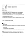
4.1 Display and operation in N (Normal) mode ................................................................... 4-2
4.2 Instructions to control the display ................................................................................. 4-3
4.2.1 F180 (SCR): Screen display instruction, Number of steps: 9 ..................................... 4-3
4.2.2 F180 (SCR) instruction: FPWIN GR Wizard ............................................................... 4-8
4.2.3 F181 (DSP) : Screen change instruction Number of steps: 3 ................................... 4-9
4.3 N mode sample program............................................................................................... 4-10
4.4 Display screen and lock with the program ................................................................. 4-11
5. Data Display and Settings in S (Switch) Mode ..................................... 5-1
5.1 Display and operation in S (Switch) mode .................................................................... 5-2
5.2 S mode sample program ................................................................................................. 5-3
6. Data Display and Settings in R (Register) Mode .................................. 6-1
6.1 Display and operation in R (Register) mode ................................................................. 6-2
6.2 Operation in R (Register) mode ..................................................................................... 6-3
6.2.1 Specifying the device type .......................................................................................... 6-3
6.2.2 Changing the data ....................................................................................................... 6-4
6.2.3 Changing the unit No. of COM. port ............................................................................ 6-5
7. I (I/O Monitor) Mode ................................................................................ 7-1
ii
7.1 I/O monitor ........................................................................................................................ 7-2
8. PID Control .............................................................................................. 8-1
8.1 PID Control ....................................................................................................................... 8-2
8.1.1 Operation of PID control ............................................................................................. 8-2
8.2 PID control instruction .................................................................................................... 8-3
8.2.1 F355 (PID) ................................................................................................................... 8-3
8.3 PID control sample program .......................................................................................... 8-7
8.4 Example of temperature control .................................................................................. 8-11
9. Specifications ......................................................................................... 9-1
9.1 Specifications .................................................................................................................. 9-2
9.1.1 General specifications ................................................................................................. 9-2
9.1.2 Performance specifications ......................................................................................... 9-3
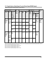
9.1.3 Specifications (High-Speed Counter/Pulse Output/PWM Output) .............................. 9-5
9.1.4 Functions and Restrictions (High-Speed Counter/Pulse Output/PWM Output) ......... 9-7
9.2 I/O Allocation .................................................................................................................... 9-9
9.3 Relays,memory Areas and Constants ......................................................................... 9-11
9.4 ASCII characters displayed in the FP-e unit ............................................................... 9-14
9.4.1 Available ASCII characters ....................................................................................... 9-14
9.4.2 ASCII code and display ............................................................................................. 9-15
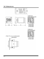
10 Dimensions .......................................................................................... 10-1
10.1 Dimensions .................................................................................................................. 10-2
iii
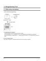
Before You Start
Operating environment (Use the unit within the range of the general specifications when installing)
*Ambient temperatures:0 ~ +55 ℃
*Ambient humidity: 30% to 85% RH (at 25°C, non-condensing)
*For use in pollution Degree 2 environment.
*Do not use it in the following environments.
-Direct sunlight
-Sudden temperature changes causing condensation.
-Inflammable or corrosive gas.
-E-xcessive airborne dust, metal particles or saline matter.
-Benzine, paint thinner, alcohol or other organic solvents or strong alkaline solutions such as
ammonia or caustic soda.
-Direct vibration, shock or direct drop of water.
- Influence from power transmission lines, high voltage equipment, power cables, power equipment,
radio transmitters, or any other equipment that would generate high switching surges.
(Min.100mm or less)
Static electricity
-Before touching the unit, always touch a grounded piece of metal in order to discharge static electricity.
-In dry locations, excessive static electricity can cause problems.
Wiring the Power Supply to the Control Unit
-Use a power supply wire that is thicker than 2 mm2 (AWG14), and twist it.
-The unit has sufficient noise immunity against the noise generated on the power line.
However, it is recommended to take measures for reducing noise such as using a isolating transformer
before supplying the power.
-Allocate an independent wiring for each power supplying line, input/output device and operating device.
-If using a power supply without a protective circuit, power should be supplied through a protective
element such as a fuse.
-Be sure to supply power to a control and an expansion units from a single power supply.
Turning on/off of the power of all the units must be conducted simultaneously.
Power supply sequence
In order to protect the power supply sequence, make sure to turn off the control unit before the
input/output power supply. If the input/output power supply is turned off before the control unit, or if the
control unit is not shut off momentarily, the controller detects change of input level, and might conduct an
unexpected operation.
Before turning on the power
When turning on the power for the first time, be sure to take the precautions given below.
• When performing installation, check to make sure that there are no scraps of wiring, particularly
conductive fragments, adhering to the unit.
• Verify that the power supply wiring, I/O wiring, and power supply voltage are all correct.
• Sufficiently tighten the installation screws and terminal screws.
• Set the mode selector to PROG. Mode.
iv
Before entering a program
Be sure to perform a program clear operation before entering a program.
Operation procedure when using FPWIN GR Ver.2
Select “Online Edit Mode” on the FPWIN GR “On line” menu.
Select “Clear Program” on the “Edit” menu.
When the confirmation dialog box is displayed, click on “Yes” to clear the program.
Request concerning program storage
To prevent the accidental loss of programs, the user should consider the following measures.
• Drafting of documents
To avoid accidentally losing programs, destroying files, or overwriting the contents of a file, documents
should be printed out and then saved.
• Specifying the password carefully
The password setting is designed to avoid programs being accidentally overwritten. If the password is
forgotten, however, it will be impossible to overwrite the program even if you want to. Also, if a
possword is forcibly bypassed, the program is deleted. When specifying the password, note it in the
specifications manual or in another safe location in case it is forgotten at some point.
• Upload protection
When the upload protection setting is specified, programs will be disalbed to be read out. If the setting
is cancelled forcibly, all programs and system registers will be deleted. Therefore, note that programs
and system registers should be managed on your own responsibility.
Backup battery
Do not install the battery when it is not used.
There is a possibility of leak if the battery remains discharged.
v
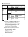
Programming tools
Type
Windows software
Windows software
conforms to IEC
61131-3
MS-DOS software
FPWIN GR
Ver. 2
FPWIN GR
Ver. 1
FPWIN Pro
Ver. 6
FPWIN Pro
Ver. 5
Restrictions
(As of Feb, 2009)
Instruction used/Function restrictions
Available.
Available from Ver. 2.2 or higher.
Not available.
Not available.
*1)
Available
Available
*2)
FPWIN Pro
Ver. 4
NPST-GR
Ver. 4
Available
Available from Ver. 4.1 or higher.
The COM. port cannot be set to MODBUS
S RTU.
Not available.
Not available.
Not available.
Instructions and functions described in *3
can not be used.
Use FPWIN GR or FPWIN Pro.
Not available.
Not available.
Not available.
Not available.
NPST-GR
Ver. 3
AFP1113V2
AFP1114V2
Handy programming
unit
AFP1113
AFP1114
AFP1111A
AFP1112A
AFP1111
AFP1112
Notes: Precautions concerning programming tools
*1) Customers who use FPWIN GR Ver. 2 can upgrade the version from
our HP free of charge.
Use Ver. 2.3 or higher to set the COM. port to MODBUS S RTU.
(MODBUS S RTU is available from FP-e main unit Ver.1.2 or higher.)
*2) FPWIN Pro Ver. 4.0 can be upgraded free of charge at our web site.
FPWIN Pro Ver. 5.0 can be upgraded free of charge at our web site.
FPWIN Pro Ver. 6.0 can be upgraded free of charge at our web site.
Panasonic Electric Works SUNX website address:
http://industrial.panasonic.com/ac/e/dl_center/software/
*3) Functions that can not be used using a handy programming unit
(AFP1113V2 and AFP1114V2):
- Screen display registry instruction <F180 (SCR)>
- Screen display switch instruction <F181 (DSP)>
- Leading edge differential instruction (Initial execution type) <DFI>
- On-delay timer instruction <TML>
- Clear multiple steps instruction <SCLR>
- Floating-point type data instruction <F309> to <F338>
- PID processing instruction <F355>
vi
Chapter 1
Features and Configurations
1-1
1.1 Features and Functions
1.1.1 Features
1. IP 66-compliant panel mounting type
Mounting panel front is waterproof and compliant with IP66, IEC standard.
Compact controller: 48 mm (H), 48 mm (W), 70 mm (D)
2. Indicator function
Simple characters and numerical values (with a minus sign) can be displayed up to 5 digits. *
4 modes (N, S, R, and I modes) can be selected.
Those 4 modes each have 2 selectable displays.
Data indication section can be displayed in red, green, or orange.
3. Operation switches
Set data can be changed.
This switch can be used as an input switch.
4. Control function
In addition to the functions of the programmable controller FP0 series, pulse output and high-speed
counter functions are installed.
General-purpose communication COM port is included as standard unit.
FP-e units with the calendar timer or thermocouple input function are also provided.
*Numerical values are displayed only in 16-bit. The data can be displayed in a bit, decimal, or
hexadecimal system.
1.1.2 Functions
Item
Power supply
Input
Output
Program capacity
Operation speed
I/O update and Base time
Pulse catch/Interrupt input
Description
24V DC
*1)
8 points
(24V DC)
6 points (5 points : Tr. NPN 0.5A, 1 point : Ry 2A)
2.7 k step
0.9 µ/step (Basic instruction)
*2)
2 ms
6 points in total (High-speed counter included)
Single phase: 4 points (10 kHz in total)
High-speed counter
*3)
Dual phase: 2 points (2 kHz in total)
*4)
Pulse output
2 points (10 kHz in total)
RS232C/RS485 (according to models)
COM port
* Must be provided aside from tool ports
*1) Thermocouple input type: 6 points
*2) Thermocouple input type: 2 to 3 ms (Typical), Max: 15 ms. (The time takes longer every 250 ms.)
*3) Thermocouple input type: 5 kHz (Single phase), 1 kHz (Dual phase)
*4) Thermocouple input type: 5 kHz
1-2
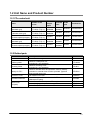
1.2 Unit Name and Product Number
1.2.1 FP-e control unit
Name
Number of I/O
points
FP-e control unit
(Standard type)
FP-e control unit
(Calendar timer type)
FP-e control unit
(Thermocouple input type)
FP-e control unit
(Standard type)
FP-e control unit
(Thermocouple input type)
Input: 8/Output: 6
(Tr. NPN: 5, Ry: 1)
Input: 8/Output: 6
(Tr. NPN: 5, Ry: 1)
Input: 6/Output: 6
(Tr. NPN: 5, Ry: 1)
Input: 8/Output: 6
(Tr. NPN: 5, Ry: 1)
Input: 6/Output: 6
(Tr. NPN: 5, Ry: 1)
Thermocouple
input
Not
available
Not
available
Calendar
timer
COM
port
Product No.
Not
available
RS232C
AFPE224300
Available
RS232C
AFPE224305
2 points
Available
RS232C
AFPE214325
Not
available
Not
available
Not
available
RS485
AFPE224302
RS485
AFPE214322
2 points
1.2.2 Related parts
Name
Terminal driver
Rubber gasket
Mounting frame
Battery for FPΣ
Protective cover
Terminal socket set
Panel cover
(20-pack)
Description
Used for connecting a terminal
Used for a waterproof unit
(included in a unit package)
Used for mounting a unit.
(included in a unit package)
Used for calendar timer and operation memory backup.
(Included in calendar timer function-provided type and
themocouple input type)
Oil resistant soft cover
Set of four types of terminal socket for FP-e
(Maintenance parts)
Color: Black, with Brand name·FP-e mark
Color: Ash gray, without Brand name·FP-e mark
Color: Black, without Brand name·FP-e mark
Product No.
AFP0806
ATC18002
ATA4811
AFPG804
AQM4803
AFPE804
AFPE803
AFPE805
AFPE806
1-3
1.3 Programming Tool
1.3.1 When using a tool software
- Tools needed for programming
1. Programming tool software
· The tool software can also be used with the FP series.
· The "FPWIN GR Ver. 2” or “FPWIN Pro Ver. 6” (for Windows) is used with FP-e controllers.
· Note that the earlier “FPWIN GR Ver. 1,” “NPST-GR (DOS version), or “FP programmer” cannot be
used.
2. PC connection cables
This cable is needed for connection between the FP-e unit and the computer.
1-4
Software environment and suitable cables
- Standard ladder diagram tool software “FPWIN GR Ver. 2”
OS
Type of software
(Operating system)
Hard disc
capacity
AFPS10520
Full type
Windows98
WindowsMe
FPWIN GR Ver. 2
English-language Upgraded version Windows2000
WindowsXP
menu
Windows Vista
Small type
Product No.
40 MB
or more
AFPS10520R
AFPS11520
Note 1) To use the “FP-e,” software Ver. 2.2 or higher is required.
The software Ver. 2.3 or higher is required to set the COM port to MODBUS S RTU.
Customers who use the Ver.2 software can upgrade it through our HP
(http://industrial.panasonic.com/ac/e/dl_center/software/) free of charge.
Note 2) Customers who use the “FPWIN GR Ver.1” can use the “FPWIN GR Ver. 2” after purchasing
the upgraded version software.
(The upgraded version software can be installed only when the “Ver.1.1” has been previously
installed.
Note 3) Small type version can be used for the “FP-e,” “FPΣ,” “FP0,” “FP1,” and “FP-M” series.
- IEC61131-3-compliant programming tool software FPWIN Pro Ver.6
OS
Hard disc
Type of software
Product No.
(Operating system)
capacity
FPWIN Pro Ver.6
English-language menu
Windows2000
WindowsXP
Windows Vista
100 MB
or more
AFPS50560
Note 1) The small type is not available for Ver.6.
Note 2) To use the “FP-e software Ver. 6.1 or higher is required.
Customers who use the Ver. 6 software can upgrade it through our HP
(http://industrial.panasonic.com/ac/e/dl_center/software/) free of charge.
- Type of computer and suitable cables
Connecter
Connecter on PLC side
Mini DIN round 5-pin
D-Sub 9-pin
Mini DIN round 5-pin streight type
Product No.
AFC8503
AFC8503S
1-5
1-6
Chapter 2
Functions and I/O specifications
2-1
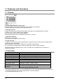
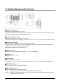
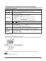
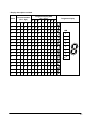
2.1 Section Names and Functions
.................................................................................
①Display mode switch
Changes the display mode to N, S, R, or I.
When the switch is pressed for 2 seconds or longer, the front switch key is locked. Pressing the switch
once more for 2 seconds or longer unlocks the key.
②Screen changeover switch
st
nd
Changes the display to 1 Screen or 2 Screen.
When the numerical data is changed, pressing the switch for one second or longer determines the data.
③Front operation switch
Changes the data. This switch is also used as the input switch.
Pressing a switch of the digit for which you would like to change the numerical value during the data
change adds one to the numerical value displayed.
(Data display blinks during the data change.)
④Display screen No.
st
nd
Indicates the screen number used currently. “1 ” or “2 ” is displayed.
⑤Display mode
Indicates “N,” “S,” “R,” or “I.”
⑥LOCK display
Shows that the switch is locked.
(This display is lit when “LOCK” using the front switch or “ALL LOCK” using the program is selected.)
⑦RUN/PROG. display
Displays the operation mode (RUN or PROG.).
⑧ERR./ALARM display
Indicates when an error or an alarm occurs.
ERR.
: Lights up if an error is detected during the self-diagnostic function.
ALARM : Lights up if a hardware error occurs, or if operation slows because of the program, and the
watchdog timer is activated.
2-2
⑨Data display (Upper section)
N and S modes
- Display the data registered using the F180 (SCR) command.
- Display the data in red, green, or orange.
R mode
- Displays the address in the memory area in green.
I mode
- Displays the external input monitor in green.
⑩Data display (Lower section)
N and S modes
- Display the data registered using the F180 (SCR) command.
- Blink when the numerical value is changed.
- Display the data in red, green, or orange.
R mode
- Displays the data in the memory area in green.
I mode
- Displays the external output monitor in green.
⑪Setting display
Indications (e.g.●, ºF, ºC, h, m, s, SV, and PV) and dot between the digits can be displayed individually
by the ladder program.
⑫Mode switch (RUN/PROG.)
Changes the mode of the FP-e unit to RUN or PROG. Modes can also be changed from the
programming tool.
When performing remote switching from the programming tool, the position of the mode switch and the
actual mode of operation may differ.
Verify the mode with the RUN/PROG. display on the front.
When power is supplied, the mode displayed is activated.
⑬Tool port (RS232C)
Used to connect a programming tool.
A commercial mini-DIN 5-pin connector is used for the tool port on the control unit.
Pin No.
1
2
3
4
5
Name
Signal ground
Send data
Receive data
(Not used)
+5V
Abbr.
SG
SD
RD
+5V
Signal direction
Unit → External device
Unit ← External device
Unit → External device
*The followings are default settings. Use the system register to change the settings.
Baud rate---------------------------9600bps
Character bit length--------------8 bit
Parity check------------------------Odd parity
Stop bit------------------------------1 bit
⑭Power supply/COM port connector
⑮Input connector
⑯Output connector
⑰Battery cover
Note: Colors in the display section
④ to ⑦ and ⑪: green ⑧: red
⑨ and ⑩: red, green, or orange (N and S modes), green (R and I modes)
2-3
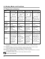
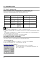
2.2 Display Modes and Functions
2.2.1 Display modes and functions
N mode
(Normal mode)
S mode
(Switch mode)
R mode
(Register mode)
Registered by F180
(SCR) command
Registered by F180
(SCR) command
Data monitor of the
internal memory
Number of
screens
2
2
2
2
Display in
the upper
section
Arbitrary data
display
(Characters/Nume
rical values)
Arbitrary data
display
(Characters/Nume
rical values)
Address in the
memory area
· Input status
monitor
·Thermocouple
input CH.0 monitor
Display in
the lower
section
Arbitrary data
display
(Characters/
Numerical values)
Arbitrary data
display
(Characters/
Numerical values)
Operation
switch
Used for changing
numerical values
Used as the input
switch
Example
Using the F180
(SCR) command, the
elapsed value on the
counter is displayed
in the upper section,
and the set value is
displayed in the
lower section. The
set value can be
changed with the
front operation
switch.
Using the F180
(SCR) command, the
message is
displayed in the
upper section, and
the data is displayed
in the lower section.
The display
description can be
changed with the
input switch.
Mode
I mode
(I/O monitor mode)
Screen
Data in the
memory area
(Displayed in a
decimal number
system.)
Used for changing
numerical values
When program
operation is checked,
the data description
can be checked by
specifying the
arbitrary memory
area with the front
operation switch. The
data can also be
changed with the
front operation
switch.
· External I/O monitor
· Thermocouple input
monitor
· Output status
monitor
·Thermocouple
input CH.1 monitor
Used as the input
switch
When program
operation is checked,
external I/O status is
monitored. The front
operation switch can
be used as the input
switch.(However, the
input status of the front
operation switch
cannot be monitored.)
Note 1) Whenever the display mode switch is pressed, the mode displayed changes as follows:
N→S→R→I→N. The display can also be switched from the program using the F180 (DSP)
command.
Note 2) When the display mode switch is pressed for 2 seconds or longer, the front switch is locked.
Pressing the switch once more for 2 seconds or longer unlocks the switch.
st
nd
Note 3) Screen changeover switch changes the display to 1 Screen or 2 Screen.
Note 4) When the numerical values are changed, pressing the screen changeover switch for one second
or longer determines the data.
Note 5) The operation switches can also be used as input switches in all modes.
Reference: A.2 I/O Allocation
2-4
2.2.2 Mode Displays
N (Normal) mode
Screen is registered using the F180 (SCR) command.
*Numerical values are displayed only in 16-bit. The data can be displayed in
a bit, decimal, or hexadecimal system.
S (Switch) mode
Screen is registered using the F180 (SCR) command.
R (Register) mode
Screen cannot be defined using the F180 (SCR) command.
I (I/O monitor) mode
Screen cannot be defined using the F180 (SCR) command.
2-5
2.3 Input and Output Specifications
2.3.1 Input specifications
- DC input specifications (X0 toX7)
Item
Number of input
Insulation method
Rated input voltage
Operating voltage range
Rated input current
Input points per common
ON voltage/ON current
OFF voltage/OFF current
Approx. 5.1 kΩ (X0, X1)
Approx. 5.6 kΩ (X2 to X7)
Note)
50 µs or less (X0, X1)
Note)
100 µs or less (X2 to X5)
2 ms or less (X6, X7)
Note)
50 µs or less (X0, X1)
Note)
100 µs or less (X2 to X5)
2 ms or less (X6, X7)
LCD display (I/O monitor mode)
Input impedance
Response time
Description
8 points
6 points (thermocouple input type)
Optical coupler
24 V DC
21.6 to 26.4 V DC
Approx. 4.3 mA
8 points/common,
6 points/common (thermocouple input type)
(Either the positive or negative of the input power
supply can be connected to common terminal.)
19.2 V or less / 4 mA or less
2.4 V or more / 1 mA or more
OFF to ON
ON to OFF
Operation indicator
Note) X0 through X5 are inputs for the high-speed counter and have a fast response time. If used as
normal inputs, you are recommend to insert a timer in the ladder program as chattering and noise
may be interpreted as an input signal.
Also, the above specifications apply when the rated input voltage is 24V DC and the temperature is
25 ºC.
Internal circuit diagram
X0 and X1
X2 to X5
X6 and X7
2-6
R1
5.1 kΩ
5.6 kΩ
5.6 kΩ
R2
3 kΩ
2 kΩ
1 kΩ
- Thermocouple input specifications
Item
Number of input
Temperature sensor type
Input range
Accuracy
Resolution
Conversion time
Insulation method
Specifications
2 points (CH0: WX1, CH1: WX2)
Thermocouple type K
*1)
- 30.0 to 300.0 ºC (- 22 to 572 ºF)
±0.5%FS±1.5 ºC (FS = -30 to 300 ºC)
0.1 ºC
*2)
250 ms/2CH
Between internal circuit and thermocouple input
*3)
circuit: noninsulated
Between CH0 and CH1 of thermocouple input:
PhotoMos insulation
Available
Detection function of wire
disconnection
*1)Temperature can be measured up to 330 ºC (626 ºF). When the measured temperature exceeds 330
ºC (626 ºF) or the thermocouple wiring is disconnected, “K20000” is written to the register.
*2)Temperature conversion for thermocouple input is performed every 250 ms. The conversion data is
updated on the internal data register after the scan is completed.
*3)The internal circuit and thermocouple input circuit are not insulated. Therefore, use the nongrounding
type thermocouples and sheath tubes.
Note:
- To prevent the influence of noise, use the shielded thermocouples and compensating lead wires after
grounding them. When the shielding types are not used, thermocouples and compensating lead wires
should be used less than 10 m.
- When the wire of the thermocouple is extended, be sure to use compensating lead wires according to
the thermocouple type.
- It takes about 2 seconds until the input processing is completed after the power is supplied.
Therefore, the input data is necessary to be valid after the temperature input completion flags X4E
(CH0) and X4F (CH1) turn ON.
After that, the temperature input completion flags turn on for only one scan at every time that the
temperature conversion process has been completed (every 250ms approx).
- 1 to 50 times (Average) can be set using the system register 409. The initial setting is “0.” (Average: 20
times)
Set the value to 20 or more to prevent the fluctuation of the thermocouple input value.
- For accurate temperature measurement, we recommend to warm up the unit for 30 minutes after the
power is supplied.
- Connecting/disconnecting the thermocouple input terminal block while the thermocouple unit is ON will
lower accuracy temporarily. In that case, it is recommended to warm up the unit for at least 15 minutes.
- A rapid temperature change in the thermocouple unit might change the temperature data temporarily.
- Prevent a direct air (wind) from the cooling fan built in the control panel etc. The direct air (wind) to the
thermocouple unit will lower accuracy.
Example of Input temperature and internal data processing
Input temperature
Internal data (WX1 and WX2)
- 30.0 ºC (- 22.0 ºF)
K-300 (K-220)
25.0 ºC ( 77.0 ºF)
K 250 (K 770)
200.0 ºC (392.0 ºF)
K2000 (K3920)
To display the temperature in the Fahrenheit scale (ºF), turn Y37 contact ON.
F = C x 9/5 + 32
F: Fahrenheit, C: Celsius, 0 ºC = 32 ºF, 100 ºC = 212 ºF
2-7
2.3.2 Output specifications
-Transistor output specifications (For Y0 to Y4)
Item
Description (NPN)
Number of output
5 points
Insulation method
Optical coupler
Output type
Open collector
Rated load voltage
5 to 24 V DC
Operating load voltage range
4.75 to 26.4 V DC
Max. load current
0.5 A
Max. surge current
1A
Output points per common
5 points/common
OFF state leakage current
100 µA or less
ON state voltage drop
1.5 V or less
50 µs or less (For Y0 and Y1)
OFF to ON
1 ms or less (For Y2,Y3 and Y4)
Response time
50 µs or less (For Y0 and Y1)
ON to OFF
1 ms or less (For Y2,Y3 and Y4)
Voltage
21.6 to 26.4 V DC
External power supply
6 mA/point (For Y0 and Y1)
(For driving internal circuit)
Current
3 mA/point (For Y2, Y3, and Y4)
Surge absorber
Zener diode
Operation indicator
LCD display (I/O monitor mode)
Internal circuit diagram
- Relay output specifications (Y5)
Item
Description
Number of output
1 point
Output type
Normally open (1 Form A)
Note1)
Rated control capacity
2 A 250 V AC, 2 A 30 V DC
Output points per common
1point/common
OFF to ON
Approx. 10 ms
Response time
ON to OFF
Approx. 8 ms
Mechanical
Min. 20,000,000 operations
Life time
Note2)
Electrical
Min. 100,000 operations
Surge absorber
None
Operation indicator
LCD display (I/O monitor mode)
Note1) Resistance load
Note2) Open/Close frequency: 20 times/min (at the rated control capacity)
Internal circuit diagram
2-8
2.4 Display/Front Operation Switch Specifications
- Display section specifications
Item
Description
Note)
5 digits with a decimal point. (Minus sign can also be used.)
Data display
7-segment, color selectable display (Green, red, or orange)
PV SV (Green, red, or orange)
Mark display
● ºF ºC h m s (Green)
4 modes (Green)
N : Normal mode---Simple characters, data display,
data setting/data input switch
S : Switch mode----Simple characters, data setting/PLC external
Display mode
input switch
R : Register mode---Internal data, timer/counter value reading
and writing modes
I : I/O monitor mode---I/O status display/PLC external input switch
Screen No.
(Green)
Status display
LOCK, RUN and PROG. (Green)
ERR ALARM (Red)
8 points For mode switching
1 point
For screen switching
1 point
Switch input
For data setting or external input
6 points
*Refer to the input address (below) for external input.
Negative backlight LCD
Display
(Colors in the numerical section can be changed: green, red, or orange
7-segment
6.7 mm LOCK
Size of the
PV SV 1.6 mm ERR
1.4 mm
characters
N S R I 1.7 mm ALARM
● ºF ºC h m s
1.6 mm
Note: Numerical values are displayed only in 16-bit. The data can be displayed in a bit, decimal, or
hexadecimal system.
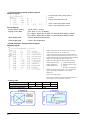
- Front operation switch (External input address)
When the front operation switch is used for external input, use the allocated addresses as shown below.
Example: When “0” is pressed during the S mode, “X30” and “X38” turn ON at the same time.
Reference: A.2 I/O allocation
2-9
2.5 Calendar timer
2.5.1 Area for calendar timer
With the clock/calendar function, data indicating the hour, minute, second, day, year
and other information stored in the special data registers DT9053 to DT9057 can be
read using the transmission instruction and used in sequence programs.
Special data
Register No.
DT9053
DT9054
DT9055
DT9056
Upper byte
Lower byte
Reading
Writing
Hour data
H00 to H23
Minute data
H00 to H59
Day data
H01 to H31
Year data
H00 to H99
Minute data
H00 to H59
Second data
H00 to H59
Hour data
H00 to H23
Month data
H01 to H12
Day- of - theweek data
H00 to H06
Available
Not available
Available
Available
Available
Available
Available
Available
Available
Available
DT9057
—
Note:
1. The area above is available for the FP-e unit with a calendar timer function.
2. The value is not fixed initially when the battery is connected. Set the appropriate value to the calendar
timer.
Lithium battery is included in the FP-e unit, but it is not connected to the unit. Connect the battery to
the unit before using the FP-e controller.
3. Put in a new battery within a minute after removing the old battery.
4. A calendar timer is available only when a battery is installed.
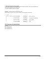
2.5.2 Setting of calendar timer function
There are two ways to set the calendar timer function as described below.
- Setting using FPWIN GR
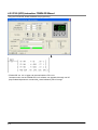
1. Press the [CTRL] and [F2] keys at the same time, to switch the screen to [Online].
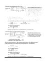
2. Select “Set PLC Date and Time” under “Tool” on the menu bar.
PLC Date and Time setting dialog box
The above steps display the “Set PLC Date and
Time dialog box” shown on the left. Input the date and time, and
click on the “OK” button.
2-10
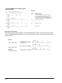
- Setting and changing using program
1. The values written to the special data registers DT9054 to DT9057, which are allocated as the
calendar timer setting area, are transferred.
2. A value of H8000 is written to DT9058.
Example: showing the date and time being written
th
Set the time to 12:30:00 on the 5 day of October, 2002 when the X0 turns ON.
2.5.3 Accuracy of calendar timer
Accuracy
200 s / month (0 ºC)
70 s / month (25 ºC)
240 s /month (55 ºC)
2-11
2.6 Limitations in data hold/non-hold function
Setting a system register can expand the data hold area. In this case, however, a back-up battery must
be previously installed.
Note 1
Product No.
Settings
Data
System register setting
Non-hold
AFPE224300
AFPE224302
Note 2
AFPE224322
System register setting with a back-up battery
Hold
AFPE224305
AFPE214325
System register setting without a back-up battery Non-hold
Note 1: System register settings are effective only when a back-up battery is installed in the FP-e control
unit.(A set value will be returned to the default value.)
Note 2: A back-up battery cannot be installed in this type of product.
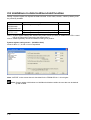
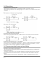
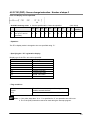
System register setting screen – (Hold/Non-hold)
Areas for Nos. 6, 7, 8 and 14 can be expanded.
Note: “NOTICE” in the screen above is described for the FPWIN GR Ver. 2.24 or higher.
Note: System register initial values on Hold/Non-hold tab are within the ones that can be backed
up with a ROM.
2-12
Chapter 3
Installation and Wiring
3-1
3.1 Installation
3.1.1 Operating environment
Operating environment (Use the unit within the range of the general specifications when installing)
*Ambient temperatures:0 ~ +55 ℃
*Ambient humidity: 30% to 85% RH (at 25°C, non-condensing)
*For use in pollution Degree 2 environment.
*Do not use it in the following environments.
-Direct sunlight
-Sudden temperature changes causing condensation.
-Inflammable or corrosive gas.
-E-xcessive airborne dust, metal particles or saline matter.
-Benzine, paint thinner, alcohol or other organic solvents or strong alkaline solutions such as
ammonia or caustic soda.
-Direct vibration, shock or direct drop of water.
- Influence from power transmission lines, high voltage equipment, power cables, power equipment,
radio transmitters, or any other equipment that would generate high switching surges.
(Min.100mm or less)
Static electricity
-Before touching the unit, always touch a grounded piece of metal in order to discharge static electricity.
-In dry locations, excessive static electricity can cause problems.
Measures regarding heat discharge:
-Always amount the unit oriented with the LCD facing upward in order to prevent the generation of heat.
Do not amount the units vertically as shown below.
-Do not install the unit as shown below.
-Do not amount the unit above which generate large heat such as heaters, transformers, or large scale
resisters.
Note that the ambient temperature and electrical voltage are restricted when the mounting panel is
installed at the angle of 0 (horizontal) to 60.
3-2
Mounting panel cut size (Unit: mm)
- Standard mounting panel cut size
Mounting panel cut size is shown in the diagram on
the left.
(Panel thickness: 1 to 5 mm)
-When using two or more units:
Make holes in the specified size as shown in
the diagram on the left.
-When mounting units in a row
Units can be mounted horizontally in a row. In that
case, however, waterproofing property on the unit will
be lost.
Note: When mounting the units horizontally in a row:
Mount the units oriented with the molded
spring sections of the mounting flame facing
upward and downward.
Do not mount the units vertically in a row in
order to prevent the generation of heat.
3-3
Installation space
- Leave at least 50 mm of space between the wiring ducts of the unit and other devices to allow heat
radiation and unit replacement.
- Maintain 100 mm or more space between the unit and other devices in order to allow room for
programming tool connections and wiring, or to avoid radiated noise and heat from other devices.
3-4
3.1.2 Mounting and Removing the Unit
Mounting the unit
Insert the unit into the mounting panel opening from its front and mount the mounting frame from the
unit’s rear all the way not to have any space with the mounting panel. In addition, secure the mounting
frame using screws.
Precautions for mounting
The front of the unit is waterproof, but do not forget to fix the mounting frame using screws to make
coherent a unit, rubber gasket and panel front sufficiently.
(Check the both screws are tightened to the same extent and are stable. Tightening too much might
remove the mounting frame.)
Always mount a unit with a rubber gasket to keep the unit front section’s waterproof.
Removing the unit
Loosen the screws for the mounting frame. Then, pull outward the frame while widening the hooks.
3-5
3.2 Terminal Layout Diagram and Terminal Block Wiring
3.2.1 Terminal layout diagram
-Terminal layout diagram
-Wiring diagram
3.2.2 Terminal block wiring
Terminal block used and suitable wire
A screw-down terminal block (from Phoenix Contact Co.) or equivalent is used. The suitable wires are
shown below.
-Suitable wires
Size
Nominal cross-sectional area
2
2
AWG#24 to 16
0.2 mm to 1.25mm
For the COM port and analog input section of the thermocouple input type, the suitable wire size is
2
2
AWG#28 to 16 (0.08 mm to 1.25 mm ).
-Pole terminal with a compatible insulation sleeve
When a pole terminal is used, use the following models from Phoenix Contact Co.
Parts No.
CrossManufacturer
Size
With insulating
Without insulating
sectional area
sleeve
sleeve
2
0.25 mm
AWG#24
AI 0,25-6BU
A 0,25-7
2
0.34 mm
AWG#22
AI 0,34-6TQ
A 0,34-7
Phoenix
2
0.50 mm
AWG#20
AI 0,5-6WH
A 0,5-6
Contact Co.
2
0.75 mm
AWG#18
AI 0,75-6GY
A 0,75-6
2
1.00 mm
AWG#18
A 1-6
2
0.5 mm X 2
AWG#20 X 2
AI-TWIN 2X 0,5-8WH
-Pressure welding tool for pole terminals
Model No.
Manufacturer
Parts No.
Phoenix Contact Co.
CRIMPFOX 6
3-6
Product No.
1212034
Suitable screwdriver
When tightening the terminals of the terminal block, use a screwdriver (Phoenix Contact Co. Product
No.1205037) with a blade size of 0.4 X 2.5 (Model No. SZS 0,4 X 2,5)
The tightening torque should be 0.22Nm to 0.25 Nm (2.3 kgfcm to 2.5 kgfcm)
Manufacturer
Phoenix Contact Co.
Model No.
Parts No.
SZS0,4 X 2,5
Product No.
1205037
Order product No.
AFP0806
Wiring
1. Remove a portion of the wire’s insulation.
2. Insert the wire into the terminal block until it contacts the back of the terminal block. Then, tighten the
screw clockwise to fix the wire in place.
Notes
-When removing the wire’s insulation, be careful not to scratch the core wire.
-Do not twist the wires to connect them.
-Do not solder the wires to connect them. The solder may break due to vibration.
-After wiring, make sure stress is not applied to the wire.
-In the terminal block socket construction, if the wire closes upon counter-clockwise rotation, the
connection is faulty. Disconnect the wire, check the terminal hole, and then re-connect the wire.
3-7
3.3 Power Supply Wiring
3.3.1 Power supply wiring
Power supply wire
To minimize adverse effects from noise, twist the wires of the power supply cable.
Power supply type
-To protect the system against erroneous voltage from the power supply line, use an insulated power
supply with an internal protective circuit.
-The regulator on the FP-e is a non-insulated type.
-When using a power supply device without an internal protective circuit, male sure power is supplied to
the unit through a protective element such as a fuse.
Power supply voltage
Rated voltage
Operating voltage range
24 V DC
21.6 V DC to 26.4V DC
Wiring system
Isolate the wiring systems to the control unit, input/output devices, and mechanical power devises.
Power supply sequence
-The power supply sequence should be set so that power to the FP-e is tuned off before the input/output
power turns off.
-If the input/output power supply turns off before the power to the FP-e turns off, the FP-e will detect the
input fluctuations and may start an unscheduled sequential operation.
3-8
3.3.2 Grounding
Grounding to prevent noise
Under normal conditions, the inherent noise resistance is sufficient. However, in situations of excessive
noise, ground the instrument to increase noise suppression.
Use an exclusive ground
2
- For grounding purpose, use wiring with a minimum of 2 mm . The grounding connection should have a
resistance of less than100Ω.
- The point of grounding should be as close to the FP-e unit as possible. The ground wire should be as
short as possible.
- If two devices share a single ground point, it may produce an adverse effect. Be sure to use an
exclusive ground for each device.
Note: Depending on the surroundings in which the FP-e unit is used, grounding may cause
problems.
Example: The power supply line of the FP-e unit is connected to the function earth through a varistor. If
there is an irregular potential between the power supply line and the earth, the varistor may
be shortened.
Do not ground an FP-e function earth terminal when grounding a plus (+) terminal of the power
The FP-e tool port shielding and function earth terminal are connected.
In some computers, the SG terminal of RS232C port and connector shielding are connected.
When the FP-e is connected to a computer with a plus (+) terminal grounded, therefore, an FP-e’s minus
(-) terminal is connected with the function earth terminal. As a result, short circuit occurs which may lead
to the breakage of FP-e and its neighboring parts.
3-9
3.4 Wiring of Input and Output
3.4.1 Input wiring
- Connection of photoelectric sensor and proximity sensor
- Precaution when using LED-equipped reed switch
When a LED is connected in series to an
input contact such as LED-equipped reed
switch, make sure that the ON voltage
applied to the FP-e input terminal is greater
than 19.2V DC. In particular, take care
when connecting a number of switches in
series.
3-10
- Precaution when using two-wire type sensor
When the input of FP-e does not turn off
because of leakage current from the
two-wire type sensors (e.g. photoelectric
sensor and proximity sensor), the use of
a bleeder resistor is recommended, as
shown in the diagram on the left.
The formula below is based on an input
impedance of 5.6 kΩ The input
impedance varies depending on the
input terminal number.
I : Sensor’s leakage current (mA)
R: Resistance of the bleeder resistor (kΩ)
The OFF voltage of the input is 2.4V. Determine the value of bleeder resistor ”R” so that
the voltage between the COM terminal and the input terminal will be less than 2.4V.
The wattage (W) of the resistor is:
Normally, use a value that is 3 to 5 times determined for the value of “W.”
- Precautions when using LED-equipped limit switch
If the input of FP-e does not turn off
because of the leakage current from
the LED-equipped limit switch, the use
of a bleeder resistor is recommended
as shown in the diagram on the left.
r : Internal resistor of limit switch
(kΩ)
R : Resistance of the bleeder resistor (kΩ)
The OFF voltage of input is 2.4V. When the power supply voltage is 24V, determine the value
for the bleeder resistor “R” so that the current will be greater than “I” as shown below:
“R” of the bleeder resistor is:
The wattage (W) of the resistor is:
Normally, use a value that is 3 to 5 times determined for the value of “W.”
3-11
3.4.2 Output wiring
Protective circuit for inductive loads
-With an inductive load, a protective circuit should be installed in parallel with the load.
-When switching DC inductive loads with relay output type, be sure to connect a diode across the ends
of the load.
Precautions when using capacitive load
When connecting large rush current loads, install a protection circuit (below) to minimize their effect.
Provide over-load protection with an external fuse
There is no fuse protection built into the output circuit. Therefore, in order to protect against overheating
of the output circuit by possible short circuit, install an external fuse at each point. However, in cases
such as short circuits, the control unit itself may not be able to be protected.
3.4.3 Common precautions for input and output wiring
Separate the input, output, and power wiring
- Be sure to select the thickness (dia.) of the input and output wires while taking into consideration the
required current capacity.
- Arrange the wiring so that the input and output wiring are separated, and these wiring are separated
from the power wiring, as much as possible. Do not route them through the same duct or bind them
together.
- Separate the input or output wire from the power’s high voltage wire by at least 100 mm /3.937 in.
3-12
3.5 Wiring COM Port
Terminal layout
- Power supply and COM port
- COM Port specifications
COM port type
Isolation status with the
internal circuit
Transmission distance
Baud rate
Terminal resistance value
Communication method
Synchro system
RX232C
*Note 2
Non-isolated
RS485
Isolated
15 m
1200 m
*Note 3, 4
300, 600, 1200, 2400, 4800, 9600, 19200 bit/s
9600, 19200 bit/s
−
120 Ω
Half-duplex
Synchronous communication method
Stop bit: 1-bit/2-bit
Parity: None/Even/Odd
Transmission data format Data length: 7-bit/8-bits
Beginning code: STX available/STX not available
Ending code: CR/CR+LF/None/ETX
Data output order
Starting from 0 bit per character
*Note 5, 6
No. of connected units
−
99
- General-purpose communication
Communication mode
- Computer link
- MODBUS S RTU *Note7
Note1) When communicating between FP-e and other device, it is recommnedable to perform resend
Processing as it may be affected by excessive noise depending on the environments installed.
Note2) For RS232C wiring, be sure to use shield wires for higher noise immunity.
Note3) Set the baud rate of RS485 to both FP-e system register and FP-e internal switch. Set the baud
rate of RS232C to FP-e system register.
Note4) After sending a command from the FP-e in RS485
communication, send a response from the receiving device to
the FP-e after the following time has been elapsed.
9600 bit/s: 2 ms or longer
19200 bit/s: 1 ms or longer
It takes at least 1 scan time (at least 2 ms) for the FP-e to send
back a response after receiveing the command.
Note5) When our C-NET Adapter or other RS485 device than recommended is connected in the system,
the maximum connection number is limited to 32 units.
Note6) For a RS485 converter on the computer side, SI-35 (from LINE EYE Co., Ltd.) is recommended.
(When SI-35 is used in the system, up to 99 units can be connected.)
Note7) MODBUS S RTU (binary communication) is available with FP-e Ver. 1.2 or higher.
3-13
- Settings when shipped from factory
System register
Description
No.412
Computer Link
Character bit: 8 bits
Parity check: odd
Stop bit: 1 bit
No.413
Header: STX not exist
Terminator: CR
No.414
Baud rate: 9600 bit/s
No.415
Unit No.: 1
No.416
Modem: Not enable
Reference: 11.1.1 System register list
- Suitable wires (twisted wire)
Size
Conductor cross-sectional area
2
2
AWG#28 to 16
0.08 mm to 1.25 mm
Use a shielded wire of the above wiring. It is recommend to ground the shield section.
Reference: 3.2 Terminal layout and terminal block wiring
3-14
- Recommended cables for RS485 communication
Use the transmission cables shown below for the FP-e RS485 communication system.
Conductor
Insulator
Cable
Cable
Applicable cables
Resistance
Size
Material
Thickness Diameter
(at 20 °C)
2
0.5 mm
HITACHI
Twist pair
Max.
Max.
Approx.
2
(AWG20)
Polyethylene
KPEV-S0.5 mm × 1P
with shield
33.4 Ω/km
0.5 mm
7.8 mm
or more
Belden Inc. 9207
2
0.75 mm
2
Max.
Max.
Approx.
VCTF0.75 mm × 2C
VCTF
(AWG18)
PVC
25.1 Ω/km
(JIS)
0.6 mm
6.6 mm
or more
*1. Use shielded type twist cables.
*2. Use only one type of the transmission cables.
Do not mix different types of the cables.
*3. Use twist pair cables under a bad noise environment.
*4. When connecting two cables to the “+” and “−”
terminals of the COM port (RS485), use the above
cables of which conductor cross section is 0.5 to 0.75
2
mm , and the cross sections of two cables should be
the same.
- RS485 wiring and terminal station setting
1. For the FP-e unit at RS485 terminal station, wire the transmission line (−) terminal and E-terminal
using a short circuit.
2. For RS485 transmission line, three or more pairs of cables should not be connected to one station.
When using shielded cables for RS485 transmission line, connect one end of the shielded cable to the
ground. Provide an exclusive ground for each FP-e power supply section and RS485 transmission
shield line. Do not share a ground with other lines.
3-15
3.6 Safety Measures
3.6.1 Safety measures
System design
In applications in which FP-e is used, malfunctions may occur for the following reasons:
-Power on timing difference between the FP-e system and input/output or mechanical power devices.
-Response time lag when a momentary power failure occurs.
-Abnormality in the FP-e unit, external power supply, or other devices.
In order to prevent a malfunction resulting in system shutdown, take the adequate safety measures as
listed below:
- Interlock circuit
When a motor clockwise/counter-clockwise operation is controlled, provide an interlock circuit on the
outside of the FP-e unit.
- Emergency stop circuit
Add an emergency stop circuit on the outside of the FP-e unit to turn off the output devices in order to
prevent a system shutdown or an irreparable accident when malfunction occurs.
- Start up sequence
The FP-e should be operated after all of the input/output devices and power devices are energized.
Procedure:
-After power is supplied to the FP-e unit, switch the mode from PROG. to RUN.
-Install the timer circuit to delay the FP-e startup.
Note: When stopping the FP-e unit, the I/O devices should be turned off after the unit has stopped
operating.
- Secure grounding
When grounding the FP-e unit next to an inverter, or other such device that produces high-voltage due to
switching, avoid common grounding. Use an exclusive ground connection for each device.
3-16
3.6.2 Momentary power failures
Operation of momentary power failures
If the duration of the power failure is less than 10 ms, the FP-e unit continues to operate. If the power is
turned off for 10 ms or longer, operation changes depending on the combination of units, the power
supply voltage, and other factors. (In some cases, operation may be the same as that for a power supply
reset.)
3.6.3 Protection of power supply and output sections
Power supply
An insulated power supply with an internal protective circuit should be used. The power supply for the
control unit operation is a non-insulated circuit, so if an incorrect voltage is directly applied, the internal
circuit may be damaged or destroyed. If using a power supply without a protective circuit, power should
be supplied through a protective element such as a fuse.
Protection of output
If current exceeding the rated control capacity is being supplied in the form of a motor lock current or a
coil shorting in an electromagnetic device, a protective element such as a fuse should be attached
externally.
3-17
3.7 Memory backup battery
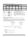
3.7.1 Installation of memory backup battery
(For FP-e unit with a calendar timer function)
Although FP-e units with a calendar timer have a built-in lithium battery, a lithium battery connector is not
connected to an FP-e unit connector. Follow the procedure as shown below to connect them.
1. Open the battery cover on the top of the FP-e
unit.
2. Connect the lithium battery connector to the
FP-e unit connector.
3. Place a lithium battery in the battery holder in
the FP-e unit.
4. Close the battery cover.
Note: A calendar timer is available only when a battery is installed.
Install a new battery within a minute after removing the old battery.
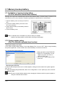
3.7.2 System register setting
(For FP-e unit with a calendar timer function)
- Setting the battery error alarm
In the system register default settings, “No.4 Alarm Battery Error” is set to “OFF.” When using the battery,
set system register No. 4 of the control unit so that the battery error alarm is turned on.
PLC Configuration setting dialog box
- Setting procedure using FPWIN GR
1. Select “PLC Configuration” on the
“Option (O)” menu, and click on
“Action on Error” tab.
2. Turn on “No. 4 Alarm Battery Error”
check box.
- Specifying the hold area
In order to use backup functions such as data registers, settings must be entered for system registers
Nos. 6 to 12.
For hold area setting using FPWIN GR, select “PLC Configuration” on the “Option (O)” menu, and click
on “Hold/Non-hold.”
Note: Be sure to install a lithium battery when changing the hold area with the system register or
using the calendar timer function.
3-18
Chapter 4
Display and Settings in N (Normal) Mode
4-1
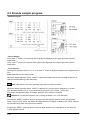
4.1 Display and operation in N (Normal) mode
Operation examples
- Values of EV0 and SV0 are displayed in the upper and lower sections of the controller screen
respectively, using the F180 (SCR) instruction.
- Pressing the operation switches (“0” to “5”) when the value (indicated in decimal or hexadecimal
system) is displayed in the lower section changes the value in each digit.
When the ASCII code or bit is displayed in the lower section, however, it cannot be changed.
- In the data change mode after the operation switch “0” to “5” is pressed, the data in the lower section
blinks.
- For writing the changed data, press the screen changeover switch “1/2/SET” for about one second.
Then, the blinking stops and the data is written.
- For canceling the data change process before the data is not completely changed, press the operation
switch “5” for about one second. Then, blinking the display data stops.
- Pressing the operation switch “5” adds or deletes a minus sign. (when displayed in a decimal system.)
- Pressing the “MODE” switch for about 2 seconds displays “LOCK.” In this mode, the data cannot be
changed even if the operation switch is pressed.
The “LOCK” status cannot be cancelled even if the power turns ON/OFF.
- For canceling the “LOCK” status, press the “MODE” switch for about 2 seconds again.
Notes:
1. Arbitrary characters and data (WX, WY, WR, SV, EV, DT, IX, or IY) can be displayed in the upper
section of the screen.
2. Arbitrary characters and data (WY, WR, SV, EV, DT, IX, or IY) can be displayed in the lower section of
the screen.
3. Numerical values are displayed only in 16-bit. (The data can be displayed in a bit, decimal, or
hexadecimal system.
- In a decimal system display: K-32768 to K32767
- In a hexadecimal system display: H0000 to HFFFF
4. The front switches can be used as the input contact switches “X38” to “X3F.” (Available in the “LOCK”
mode as well.)
5. Switching the power ON/OFF or RUN/PROG. mode cancels the data changed using the front
switches.
6. Only the data displayed in the lower section can be changed with the operation switches “0” to “5”.
4-2
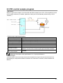
4.2 Instructions to control the display
4.2.1 F180 (SCR): Screen display instruction, Number of steps: 9
Screen display instructions in the N and S modes of FP-e unit
The FPWIN GR wizard facilitates the programming.
S1: Used to specify the registration screen.
S2: Used to specify the head of the screen display control data (3 words).
S3: Used to specify the data displayed in the upper section
(Numerical values are displayed only in 16-bit.)
S4: Used to specify the data displayed in the lower section.
(Numerical values are displayed only in 16-bit.)
Example:
F180 (SCR), K0, DT0, EV0, SV0
st
Registration of N mode 1 screen
Control data: DT0, DT1, DT2
Upside display data: EV0
Downside display data: SV0
- Available memory areas A: Can be specified
S1
S2
S3
S4
Display mode and
No. (0 to 3 can be
specified.)
Head address of the
area to specify the
display measure.
Area which stores
the data to be
displayed in the
upper section.
Area which stores
the data to be
displayed in the
lower section.
N/A: Cannot be specified
(Unit: Word)
Index
H
modifier
WX
WY
WR
SV
EV
DT
IX
IY
K
A
A
A
A
A
A
A
A
A
A
A
A
A
A
A
A
A
N/A
N/A
N/A
N/A
A
A
A
A
A
A
A
A
A
N/A
N/A
A
N/A
A
A
A
A
A
A
A
N/A
N/A
A
Note: Special register “DT9***” cannot be specified for the lower section display data “S4.”
This instruction cannot be used in the interrupt program.
4-3
- Specifying the “S1” registration screen
Display type of the FP-e unit can be specified.
Values for “S1”
Display type
K0
N mode 1 st screen
K1
N mode 2 nd screen
K2
S mode 1 st screen
K3
S mode 2 nd screen
- Flag conditions
R9007
R9008
(ER)
Turns ON when the area specified using the
Index modifier exceeds the limit.
Turns ON when the “S1” or “S2” value is outside
of the range specified.
- Configuration of “S2” screen display control data
st
1 word
Low byte
● ºF
ºC h
m
s
SV PV
0: Not displayed, 1: Displayed
st
1 word
High byte
Undefined (Specify “0.”)
2
nd
Upper setting
0:Displayed
1:Not displayed
Lower setting
0: Displayed
1:Not displayed
word
Low byte
(Display control: Upper section)
Upper display
Decimal point display
mode
nd
2 digit
rd
3 digit
th
4 digit
th
5 digit
rd
3 -upper digit
000: Signed Dec 5 digits
001: Hex 4digits or BCD 4digits
010: Bit
011: ASCII code of five characters
100: 7-segment Data
101: Undefined
110: Undefined
111: Undefined
0: Not displayed
1: Displayed
101 and later: Undefined.
Error occurs when the undefined data is
specified.
Reference: “ASCII code of five characters” and “7 segment Data. ” (See the following page.)
4-4
2nd word
High byt High byte
(Display control: Upper section)
Digit delete
st
1 digit
nd
2 digit
rd
3 digit
th
4 digit
th
5 digit
Color
Color
Zero
suppression
0: Displayed,
1: Not displayed
00: Undefined
(Displayed in green when defined)
01: Green
10: Red
11: Orange
0: Available
1: Not available (All digits displayed)
* When a value with a decimal point is to be displayed in the “Signed Dec 5 digits” mode, the value(s)
before the decimal point should be displayed.
rd
Low byte
(Display control: Lower section)
nd
Same as the low byte display control data for 2 word
rd
High byte
(Display control: Lower section)
nd
Same as the high byte display control data for 2 word
3 word
3 word
4-5
- Examples of control register
st
1 word
“0 0 0 0 0 0 0 0
↑
Upper/Lower section
display
1000
↑
●
0 0 1 1” = H83
↑ ↑
SV PV
2nd word
“0 1 0 0 0 0 0 0
0 0 0 0 0 0 0 0” = H4000
↑
↑
↑
Red All digits
Decimal point: Not displayed
Zero suppression
rd
3 word
“0 1 1 0
0000
0 0 0 0 0 0 0 0” = H6000
↑
↑
↑
Orange All digits Decimal point: Not displayed
Zero suppression
- ASCII code and its display
When 5 characters from DT0 are displayed (for 5 bytes from DT0):
DT0
H32
H31
(H32:2, H31:1)
DT1
H34
H33
(H34:4, H33:3)
DT2
H36
H35
(H36:6, H35:5)
The ASCII code above are displayed as follows.
- 7-segment data and its display
When the data of 5 digits from DT0 are displayed (Lower byte in 1 word stores the data of 1 digit.):
DT0
H3F
(7-segment display data H3F: 0) 5th digit (highest-order digit)
DT1
H6
(7-segment display data H6: 1)
4th digit
DT2
H5B
(7-segment display data H5B: 2)
3rd digit
DT3
H4F
(7-segment display data H4F: 3)
2nd digit
DT4
H66
(7-segment display data H66: 4)
The 7-segment data above are displayed as follows:
1st digit (lowest-order digit)
Note) An arbitrary segment can be displayed using this function.
4-6
- Display description and data
Value
7-segment display data
(for 1 digit)
Conversion data
(for 1 digit)
7-segment display
g
f
e
d
c
b
a
0
0
0
0
0
0
0
1
1
1
1
1
1
1
0
0
0
1
0
0
0
0
0
1
1
0
2
0
0
1
0
0
1
0
1
1
0
1
1
LSB
3
0
0
1
1
0
1
0
0
1
1
1
1
a
4
0
1
0
0
0
1
1
0
0
1
1
0
b
5
0
1
0
1
0
1
1
0
1
1
0
1
c
6
0
1
1
0
0
1
1
1
1
1
0
1
d
7
0
1
1
1
0
0
1
0
0
1
1
1
e
8
1
0
0
0
0
1
1
1
1
1
1
1
f
9
1
0
0
1
0
1
1
0
1
1
1
1
g
A
1
0
1
0
0
1
1
1
0
1
1
1
B
1
0
1
1
0
1
1
1
1
1
0
0
C
1
1
0
0
0
0
1
1
1
0
0
1
D
1
1
0
1
0
1
0
1
1
1
1
0
E
1
1
1
0
0
1
1
1
1
0
0
1
F
1
1
1
1
0
1
1
1
0
0
0
1
MSB
4-7
4.2.2 F180 (SCR) instruction: FPWIN GR Wizard
Using the FPWIN GR wizard facilitates the programming.
↓
* FPWIN GR Ver. 2.2 or higher can be used with the FP-e unit.
Customers who use the FPWIN GR Ver.2 software can upgrade it through our HP
(http://industrial.panasonic.com/ac/e/dl_center/software/) free of charge.
4-8
4.2.3 F181 (DSP) : Screen change instruction Number of steps: 3
FP-e unit display can be specified.
- Available memory areas A: Can be specified N/A: Cannot be specified
S
Display mode and
No. (0 to 7 can be
specified.)
WX
WY
WR
SV
EV
DT
IX
IY
K
A
A
A
A
A
A
A
A
A
(Unit: Word)
Index
H
modifier
A
A
- Operation
The FP-e display mode is changed to the one specified using “S.”
- Specifying the “S1” registration display
Display type of the FP-e unit can be specified.
Values for “S”
Display type
K0
N mode 1st screen
K1
N mode 2nd screen
K2
S mode 1st screen
K3
S mode 2nd screen
K4
R mode 1st screen
K5
R mode 2nd screen
K6
I mode 1st screen
K7
I mode 2nd screen
- Flag conditions
R9007
R9008
(ER)
Turns ON when the area specified using the index
modifier exceeds the limit.
Turns ON when the value “S” is not “0” to “7.”
Notes: 1. If the value other than “0” to “7” is specified for “S,” an operation error will occur.
2. The F181 (DSP) instruction cannot be used during the interrupt program.
4-9
4.3 N mode sample program
- Sample program
- Screen display
st
On N mode 1 screen, EV0 (red) and SV0 (orange) are displayed in the upper and lower sections
respectively.
nd
On N mode 2 screen, EV1 (red) and SV1 (green) are displayed in the upper and lower sections
respectively.
- Front switches
st
Pressing the operation switch “0” to “4” on N mode 1 screen changes the mode to the change mode for
SV0.
Note: Data blinks in the change mode.
When the display selection switch “1/2/SET” is pressed for about one second, the data for the SV0 is
changed and the blinking of the data stops.
Note: Data which is out of the specified range (16-bit) cannot be written.
nd
When the display selection switch “1/2/SET” is pressed, the current screen changes to 2 screen.
nd
The operation switches (“0” to “5”) are locked by the program on 2 screen. (Y32 is ON.)
Even when the operation switch is pressed, therefore, SV1 cannot be changed.
Reference: For further information, see “Locking the Switch” in A.2 I/O Allocation.”
Pressing the “MODE” switch for about 2 seconds locks both display selection switch and operation
switch. In this “LOCK” status, the display and data cannot be changed. In addition, the “LOCK” status is
not cancelled even when the power turns ON/OFF.
Pressing the “MODE” switch for about 2 seconds again unlocks the “LOCK” status. At this time, the
“LOCK” display turns off.
4-10
4.4 Display screen and lock with the program
- Sample program
- Program operation
Turning ON the “R0” to “R6” switches the screen to be displayed.
Note: Even if the “MODE” switch or the “1/2/SET” switch is pressed under the condition that the “R0” is
always set to ON using the sample program, the N1 screen cannot be switched to other screen. Using
this function prevents operation mistake of the front switch.
Setting the “Y30” to “Y34” to ON locks the front switch. Using this function prevents operation mistake of
the front switch.
Reference: For further information, see “Locking the Switch” in A.2 I/O Allocation.
4-11
4-12
Chapter 5
Data Display and Settings in S (Switch)
Mode
5-1
5.1 Display and operation in S (Switch) mode
The ASCII characters “FP-E-“ and the description of the “DT20” are displayed in the upper and lower
sections of the controller screen respectively, using the F180 (SCR) instruction.
The front switches can be used as the input contacts “X30” to “X37.” The switch can also be used to
change the display description, and so on depending on the program.
Note: 1. The front switches are allocated as the input contacts “X30” to “X37” and “X38” to “X3F.”
“X30” to “X37”: The switch can be locked using the program.
“X38” to “X3F”: The switch cannot be locked using the program.
Reference: For further information, see “Locking the Switch” in A.2 “I/O Allocation.”
2. Pressing the “MODE” switch for about 2 seconds displays the “LOCK.”
In this condition, the input contacts “X30” to “X37” cannot be used, but “X38” to “X3F” can be
used.
3. The input contacts “X30” to “X3F” do not turn ON during the first scanning after the mode is
switched to RUN mode.
4. Pressing the MODE switch turns on “X37” and changes the screen mode.
5-2
5.2 S mode sample program
- Sample program
- Screen display
st
On S mode 1 screen, the ASCII character “FP-E-“ is displayed in the upper section in orange.
Reference: See “ASCII character and 7-segment display” in Appendix A of this manual.
nd
On 2 screen, the data of “DT20” is displayed in green.
- Front switches
- When the front switch “0” is pressed, “X30” turns ON and “30” is displayed in the lower section of the
screen.
- When the front switch “1” is pressed, “X31” turns ON and “31” is displayed in the lower section of the
screen.
- Pressing the “MODE” switch for about 2 seconds locks all the front operation switches and “LOCK” is
displayed. In this “LOCK” status, the display cannot be changed even if the front operation switch “0” to
“5” is pressed.
5-3
5-4
Chapter 6
Data Display and Settings in R (Register)
Mode
6-1
6.1 Display and operation in R (Register) mode
1. When the device type (DT, WR, SV, or EV) in the memory area is specified using the front
operation switch, the specified device type data is displayed.
- When “PV” blinks, the device type in the memory area can be specified.
- The device No. can be specified using the switches “0” to “3.” The device type can be switched using
the switch “4” in the following order: DT→WR→SV→EV
Note: When specifying the No. which is out of the designated range, the display color in the upper
section switches from green to red and the display in the lower section turns off.
2. The specified device data can be changed using the front switch.
- When the switch “5” is pressed for about 1 second, “SV” blinks. In this status, the data can be changed.
- When the switch “0” to “5” is pressed, the data in the lower section is changed and then blinks.
- When the “1/2/SET” switch is pressed for about 1 second, the blinking stops and the data change
completes.
- For canceling the data change process before the data is not yet completely changed, press the
operation switch “5” for about one second. Then, blinking the display data stops.
- For changing to the device specification mode after the data change has completed, press the
operation switch “5” for about one second. When the mode changes to the device specification mode,
“PV” blinks.
- The mode cannot be changed to the device specification mode before the data is not yet completely
changed. Wait for the completion of the data change process or cancel the data change process to
hange the mode to the device specification mode.
Note: If you try to change the data to the one which is out of the specified range, the data is displayed in
red only when the “1/2/SET” switch is pressed, and blinking does not stop.
When the power ON/OFF or RUN/PR OG. mode switching is performed, the data which is not yet
completely changed using the front switch will be cancelled.
The data change can also be cancelled by turning Y38 ON.
(This is available for Ver. 1.1 or higher.)
st
3. Pressing the “1/2/SET” switch changes the current screen to 1 screen or 2
nd
screen.
4. When “MODE” switch is pressed for about 2 seconds, “LOCK” is displayed. In this ”LOCK”
status, the display cannot be changed even if any switches are pressed.
6-2
6.2 Operation in R (Register) mode
6.2.1 Specifying the device type
When “PV” blinks, the device type and No. can be changed.
1. Specifying the device type (Example of “EV”)
Press the switch “4” until “EV” is displayed as shown above.
Note: At this moment, the “EV0” data is displayed in the lower section.
2. Specifying the device No. (Example of “EV123”)
Specify the device No. “EV123” using the switches “0” to “3.”
Note: When specifying the No. which is out of the designated range, the display color in the upper
section changes from green to red and the data display in the lower section turns off.
6-3
6.2.2 Changing the data
1. Switching to the data change mode
- When the switch “5” is pressed for about 1 second, the “PV” display turns off and then the “SV” blinks.
While the “SV” is blinking, data can be changed.
Note: When the switch “5” is pressed for about 1 second again, the “SV” display turns off and the “PV”
display blinks. While the “PV” is displayed, the device type can be specified.
2. Changing the data
- Pressing the switch “0” to “5” changes the data displayed. The changed data blinks.
- Pressing the switch “1/2/SET” for about 1 second stops blinking. At this point, data change completes.
.................................................................................
Notes:
1. Press the operation switch “5” for about one second when the data display is blinking to cancel the
data under change.
The data change can also be cancelled by turning Y38 ON.
(This is available for Ver. 1.1 or higher.)
2. If you try to change the data to the one which is out of the specified range, the data is displayed in
red only when the “1/2/SET” switch is pressed, and blinking does not stop.
3. When the power ON/OFF or RUN/PROG. mode switching is performed, the data under change will be
cancelled.
6-4
6.2.3 Changing the unit No. of COM. port
The unit No. specified in the system register can be changed by the front switch (for Ver. 1.2 or
higher).
1. Displaying the unit No.
- Press the switch “4” to display the unit No.
2. Switching to the unit No. change mode
- When the switch “5” is pressed for about 1 second, the “PV” display turns off and then the “SV” blinks.
While the “SV” is blinking, data can be changed.
Note: When the switch “5” is pressed for about 1 second again, the “SV” display turns off and the “PV”
display blinks. While the “PV” is displayed, the device type can be specified.
3. Changing the unit No.
- Pressing the switch “0” and “1” changes the unit No. displayed. The changed No. blinks.
- Pressing the switch “1/2/SET” for about 1 second stops blinking. At this point, data change completes.
Notes:
1. Change the unit No. in PROG. mode.
The unit No. cannot be changed in RUN mode.
2. Press the operation switch “5” for about one second when the unit No. display is blinking to cancel the
unit No. under change.
3. If you try to change the data to the one which is out of the specified range (1 to 99), the changing
process of the unit No. is cancelled by pressing the “1/2/SET” switch.
4. When the power ON/OFF or RUN/PROG. mode switching is performed, the data under change will be
cancelled.
6-5
6-6
Chapter 7
I (I/O Monitor) Mode
7-1
7.1 I/O monitor
st
1. I/O status of “WX0” and “WY0” can be monitored using 1 screen.
- Example:
Note: 1. “Y6” or higher does not exist for the FP-e external output, but it can be used as the contact on
the program.
2. In case of forced input/output, the monitoring of the forced input contact is not available.
2. Temperature display of the thermocouple input can be monitored using 2nd Screen.
- Example:
Note: Turning Y37 contact ON displays the Fahrenheit degree. (ºF)
3. The front switches can be used as the input contacts “X30” to “X37.”
Note: 1. The front switches are allocated as the input contacts “X30” to “X37” and “X38” to “X3F.”
“X30” to “X37”: The switch can be locked using the program.
“X38” to “X3F”: The switch cannot be locked using the program.
2. Pressing the “MODE” switch for about 2 seconds displays the “LOCK.”
In this condition, the input contacts “X30” to “X37” cannot be used, but “X38” to “X3F” can be used.
3. Pressing the MODE switch turns on “X37” and changes the screen mode.
7-2
Chapter 8
PID Control
8-1
8.1 PID Control
8.1.1 Operation of PID control
PID is a control method widely used in the instrumentation field involving feedback control of process
quantities such as temperature, pressure, flow, and fluid level.
- Proportional operation
Proportional operation generates an output which is proportional to the input.
The amount of control is held constant.
An offset (steady-state deviation) remains.
Proportional control grows stronger as “Kp” is
increased.
Kp: Proportional gain
- Integral operation
Integral operation generates an output which is proportional to the integral time of the input.
In combination with proportional operation or
proportional-derivative operation, integral
operation removes the offset produced by these
methods.
Integral operation grows stronger as the integral
time “Ti” is shortened.
Ti: Integral time
- Derivative operation
Derivative operation generates an output which is proportional to the derivative time of the input.
The advancing characteristic of derivative
operation alleviates the adverse effect that the
delaying characteristic of the process exerts on
control.
Derivative control grows stronger as the derivative
time “Td” is increased.
In the case of pure derivative operation, control
can temporarily become ineffective if noise is
input, and this can have an adverse effect on the
process being controlled. For this reason,
incomplete differential operation is executed.
Td: Derivative time
- PID operation
PID operation is a combination of proportional, integral, and derivative operations.
If the parameters are set to the optimum values,
PID control can quickly bring the amount of control
to the target value and maintain it there.
8-2
8.2 PID control instruction
8.2.1 F355 (PID)
- PID control
- Operands
S
(Unit: Word)
Starting number of PID
parameter area (31 words)
WX
WY
WR
WL
SV
EV
DT
I
Constant
K
H
N/A
N/A
N/A
N/A
N/A
N/A
A
N/A
N/A
N/A
f
Index
modifier
N/A
N/A
(A: Available, N/A: Not Available)
- Descriptions
· PID processing is performed to hold the measured value specified by [S+2] at the set value [S+1], and
the result is output to [S+3].
· Derivative control or proportional-derivative control can be selected for the PID processing type.
· Set the PID processing coefficients (proportional gain, integral time and derivative time) and the
processing mode and cycle in the parameter table. PID processing will be performed based on these
settings.
- Types of PID processing
1. Reverse and forward operations
When a process has been changed, whether the output will be increased or decreased can be
selected.
· When the measured value decreases, “Reverse operation” is specified to boost the output (heating,
etc.).
· When the measured value increases, “Forward operation” is specified to boost the output (cooling,
etc.).
2. Derivative type (PI-D) and Proportional-derivative type (I-PD)
Derivative type (PI-D): When a set value is changed, fluctuation in the output is large, however
convergence is fast.
Proportional-derivative type (I-PD): When a set value is changed, fluctuation in the output is small,
however convergence is slow.
- Parameter table settings
* For FP-e, [S+11] to [S+30] (20 words) are used as the PID processing work area.
- Flag conditions
R9007
R9008
(ER)
Turns ON when the value set for the parameter is out of range.
The area specified using the index modifier exceeds the limit.
8-3
- Descriptions of parameters
1. Control mode: [S]
Select the type of PID processing and auto-tuning ON/OFF using the H constants.
Derivative type
(PI-D)
Reverse operation
Forward operation
Value of [S]
Auto-tuning: Not executed
H0
H1
Proportional-derivative type
(I-PD)
Reverse operation
Forward operation
H2
H3
Control mode
Auto-tuning: Executed
H8000
H8001
H8002
H8003
Auto-tuning
The optimum values for the Kp, Ti, and Td of the PID parameters can be measured by checking the
process response. When auto-tuning is executed, the estimated results are reflected in the parameter
area after auto-tuning has been completed. (There may be cases in which auto-tuning cannot be
executed, depending on the process. If this happens, a value returns to the original parameter operation
value.)
Reverse and forward operations
When a process has been changed, whether the output will be increased or decreased can be
determined.
Reverse operation: When the measured process value decreases, the output will be boosted.
(Example: heating, etc.)
Forward operation: When the measured process value increases, the output will be boosted.
(Example: cooling, etc.)
Derivative type (PI-D) and Proportional-derivative type (I-PD)
When the set value is changed, the output changes.
Derivative type (PI-D): When a set value is changed, fluctuation in the output is large, however,
convergence is fast.
Proportional-derivative type (I-PD): When a set value is changed, fluctuation in the output is
small, however, convergence is slow.
2. Set value (SP): [S + 1]
Set the target value (temperature set value) within the following range which determines the amount of
process control.
K0 to K10000
3. Measured value (PV): [S + 2]
Set the current process control value (temperature data WX1 and WX2) within the following range.
K0 to K10000
4. Output value (MV): [S + 3]
The result of PID processing is stored. Use the PWM output function to output it to the process.
K0 to K10000
5. Output lower limit value: [S + 4]
K0 to K9999 (< upper limit value)
6. Output upper limit value: [S + 5]
K1 to K10000 (> lower limit value)
Specify the range of the output value (MV). The values specified for the range are output.
The limits should be as follows;
0 ≤ Output lower limit value < Output upper limit value ≤ 10000
8-4
7. Proportional gain (Kp): [S + 6]
Specify the coefficient used for PID processing.
The set value × 0.1 will be the actual proportional gain.
The setting range is K1 to K9999 (0.1 to 999.9, Specify the range in increments of 0.1.)
When the auto-tuning is selected for the specified control mode, the set value is automatically adjusted
and rewritten.
8. Integral time (Ti): [S + 7]
Specify the coefficient used for PID processing.
The set value × 0.1 will be the actual integral time.
The setting range is K1 to K30000 (0.1 to 3000 sec., Specify the range in increments of 0.1 sec.)
When the set value is “0,” the integration is not executed.
When the auto-tuning is selected for the specified control mode, the set value is automatically adjusted
and rewritten.
9. Derivative time (Td): [S + 8]
Specify the coefficient used for PID processing.
The set value × 0.1 will be the actual derivative time.
The setting range is K0 to K10000 (0 to 1000 sec., Specify the range in increments of 0.1 sec.)
When the auto-tuning is selected for the specified control mode, the set value is automatically adjusted
and rewritten.
10. Control cycle (Ts): [S + 9]
Specify the cycle for executing PID processing.
The set value × 0.01 will be the actual control cycle.
The setting range is K1 to K6000 (0.01 to 60.00 sec., Specify the range in increments of 0.01 sec.)
11. Auto-tuning progress: [S + 10]
When the auto-tuning is specified in the control mode, the progress of the auto-tuning is indicated.
The values for K1 to K5 are stored based on the progress from the default value of “0.”
When the auto-tuning has been completed, the value returns to the default value.
12. PID processing work area: [S + 11] to [S + 30]
This work area that is necessary for PID processing is used in the system.
8-5
Note:
- Precautions when executing auto-tuning
When “Execute auto-tuning” is specified using the parameter table (control mode [S]), attention should
be paid to the following points.
⋅ Before the auto-tuning is executed for the first time, confirm the range of the set values for [S] to [S +
30].
⋅ After the auto-tuning has been completed, the control mode [S] area is automatically rewritten from
H8000-H8003 to H0-H3. Make sure the mode is not rewritten again in the program.
⋅ After the auto-tuning has been completed, the optimum values are stored for the proportional gain (Kp),
the integral time (Ti) and derivative time (Td). Before executing the auto-tuning, however, the
appropriate values (e.g. the lower limit value) within the specified setting range must be set.
⋅ After the auto-tuning has been completed, the optimum values are stored for the proportional gain (Kp),
the integral time (Ti) and derivative time (Td). Be careful that the stored values are not inadvertently
rewritten.
⋅ In the auto-tuning, the optimum values for Kp, Ti and Td are calculated for the set value (SP) by
checking the fluctuations of the measured values (PV) when the output value (MV) is the upper limit
and lower limit.
During this process, the set value (SP) can exceed the measured value (PV).
⋅ The output value (MV) in the auto-tuning fluctuates at least three times:
Upper limit output – Lower limit output – Upper limit output
If the value for the auto-tuning progress remains “0” after the fluctuation is performed more than twice,
shorten the control synchronization period (Ts) and then execute the auto-tuning once more.
- Precautions during programming
⋅ A 31-word area is required for the parameter table, including the work area for processing. Take care
that other instructions do not overwrite the values in this area.
⋅ An error will not be detected even if the parameter table exceeds its area. When specifying [S], select a
number at least 31 words before the last number.
⋅ Take care that the area is not exceeded due to index modification. An error will not be detected even if
the area is exceeded.
⋅ For the current measured value [S+2], input the temperature data (WX1 and WX2).
⋅ Output the result of PID processing [S+3] to the process using the PWM output function.
⋅ For FP-e, this instruction F355 (PID) cannot be programmed in the interrupt program.
8-6
8.3 PID control sample program
- PID control
When a K-type thermocouple is connected with the thermocouple input of FP-e, PID temperature control
can be easily conducted. (In addition, parameter setting can be automatically selected using “AUTO
TUNING.”)
- Thermocouple input specifications
Item
Description
Number of input point
2 points (CH0: WX1, CH1: WX2)
Temperature sensor type K-type thermocouple
Input temperature range
- 30.0 to 300.0 ºC (- 22 to 572 °F)
Accuracy
±0.5 %FS±1.5 ºC (FS = - 30 to 300 ºC)
Resolution
0.1 ºC
Conversion time
250 ms/2CH
Between internal circuit and thermocouple input circuit: noninsulated
Insulation method
Between CH0 and CH1 of thermocouple input: PhotoMos insulation
Detection function of
Available
wire disconnection
Reference: Description of the specifications <2.3.1 Input specifications>
- Thermocouple
A thermocouple is the sensor that measures the temperature using the thermo-electromotive force
generated by the temperature difference between two metal wires connected, whose materials are
different.
8-7
- (1) Screen display setting sample program
Sample program
Screen display setting: K0 (N mode 1st
screen)
Display control data: D0 to D2
Upper section display data: DT202
Lower section display data: DT201
Screen display
Screen display setting
Display control data
st
Upper display data
: K0: N mode 1 screen
: DT0: H23: ºC, PV, SV display
nd
DT1: H6001: Signed Dec 5 digits, 2 decimal place display, Orange
nd
DT2: H2001: Signed Dec 5 digits, 2 decimal place display, Green
: DT202: Measured temperature
Lower display data
: DT201: Set temperature
- (2) PID parameter setting sample program
Sample program
DT200: Control code (H0: Reverse operation PI-D mode)
DT201: Set temperature = 55 ℃ (550∗0.1 ℃)
( Use the same unit as the one for the current temperature.)
DT202: Current temperature (Reading from WX1, unit: 0.1 ℃)
DT203: PID processing output value (automatically calculated)
DT204: PID output lower limit value (Normally, 0 %)
DT205: PID output upper limit value (Normally, 100.00 %)
DT206: Proportional gain
These are automatically
DT207: Integral time
selected in the auto-tuning
DT208: Derivative time
process.
Write them in the program.
DT209: Processing interval (Approx. 1 sec. in temperature
control. Use the same interval as the one for heater
PWM cycle.)
DT210: Auto-tuning progress
Note: DT211 to DT230 are used for the PID processing work
area. Therefore, do not use them for other uses.
- Control code
8-8
Control code
H0
H1
H2
H3
Control operation
Reverse
Forward
Reverse
Forward
Response characteristics
PI-D
I-PD
- (3) PID processing sample program
Sample program
Program
X0
: Auto-tuning start
(Auto-tuning is executed only once.)
R100
: Auto-tuning is being executed.
R130
: 16-bit data bit set
When the most significant digit bit
(K15) of the DT200 is “1”, auto-tuning
starts.
When the most significant bit (R11F)
of the DT200 is “0”, auto-tuning
completes.
: Auto-tuning completes.
: Block transfer instruction
Parameters (Kp, Ti, Td), which are
automatically adjusted in auto-tuning,
are stored.
: PID control starts.
: PID control is being executed.
: PID control stops.
R10F
F10
X1
R101
X2
F355
: PID processing instruction
Always turn to “ON” while PID control.
Notes:
1. Before starting the auto-tuning for the first time, set the parameters (Kp, Ti, Td) specified for the PID
control.
(Using the FPWIN GR data monitor facilitates the setting.)
Setting example
⋅ DT1652: K1 Proportional gain (Kp)
⋅ DT1653: K1 Integral time (Ti)
⋅ DT1654: K0 Derivative time (Td)
2. To store the PID control parameters obtained in the auto-tuning, write them in the storage type data
area (e.g., DT 1652 to DT1653) when the auto-tuning is completed.
3. An operation error will occur if the PID processing instruction is executed with a parameter that is out
of the setting range.
8-9
- (4) Heater PWM control sample program
Sample program
Program
DT203
SV1
: PID processing output
: Heating time setting
Heater control depending on PID processing result.
To turn the heater ON (100 %) when the PID
processing output DT203 is 100 % (K10000), divide
the PID processing output DT203 (K10000) by 10 and
write 100 % (1000 ms) into SV1 of heating timer.
TML0
: PWM output cycle setting
TML1
: Heating time setting
Y0
: Heater control
Setting the input timing
Set the input timings as shown below so that the temperature conversion cycle (250 ms for FP-e), PID
control cycle (DT209) and PWM output cycle (TM0) are all equal, or PID control cycle takes longer than
other two cycles.
Correct:
⋅ Tad = Tpid = Tout
⋅ Tad < Tpid > Tout
Incorrect:
⋅ Tad > Tpid < Tout
8-10
8.4 Example of temperature control
- Example of auto-tuning
Control cycle: Ts = K100 (1 s)
Selected parameter: Proportional gain (Kp) = K171 (17.1), Integral time (Ti) = K600 (60 s),
Derivative time (Td) = K150 (15 s)
Temperature (∗0.1 ℃)
Output (%)
Time (∗2 sec.)
⋅ The temperature input conversion for FP-e is performed every 250 ms. The average cycle (1 to 50
times) can be set using the system register 409. The initial setting is “0.” (Average: 20 times)
When the heat capacity of the control system is small and heating/cooling is performed at high speed,
set a value for the average time to a smaller one.
⋅ Executing the auto-tuning sets the parameters suitable for any control system automatically.
Optimum control can be conducted by changing the values (1/2 to 2 times).
Generally, Kp (proportional gain) affects on the response characteristics. As the value of Kp becomes
larger, the response error becomes smaller. When the value is too large, however, it may cause the
hunting. Ti (Integral time) greatly affects on the response characteristics. As the value of Ti becomes
smaller, the response becomes faster. When the value is too small, however, it may cause the
overshoot.
- Example of PID parameter characteristics
When Ti is changed to 30, 60, 90, and 120 under the conditions as follows:
Ts = 250, Kp = 300, Td = 1
- Example of PID processing
PID control mode: Ts = 250, Kp = 300, Ti = 60, Td =
8-11
8-12
Chapter 9
Specifications
9-1
9.1 Specifications
9.1.1 General specifications
Item
Rated voltage
Operating voltage
range
Allowed momentary
power off time
Ambient temperature
Storage temperature
Ambient humidity
Storage humidity
Breakdown voltage
Insulation resistance
Vibration resistance
Shock resistance
Noise resistance
Operating condition
Electric current
Protection
Weight
9-2
Description
24V DC
21.6 to 26.4V DC
10 ms
0 to +55ºC
-20 to +70ºC
30 to 85%RH (at 25 ºC, non-condensing)
30 to 85%RH (at 25 ºC, non-condensing)
Between insulated circuits: 500V AC,
Insulated circuit
1 min However, between 3) Output
1) Power supply terminal, function
terminal (Y5, COM) and other
earth, Input terminal (A0,A1),
insulated circuits: 1500V AC, 1 min
COM.(RS232C)Terminal
(Cut-off current: 10mA, excluding the
2) Input terminal (COM, X0 to Xn)
barrister for protection)
3) Output terminal (+, −, Y0 to Y4)
Between insulated circuits: 100 MΩ or
4) Output terminal (Y5, COM)
higher
5) COM. (RS485) terminal
(measured with 500V DC)
10 to 55 Hz, 1 cycle/min.
Double amplitude: 0.75 mm, 10 min. on X, Y , and Z axes
2
98 m/s , 4 times on X, Y, and Z axes
1000V (p-p) with pulse widths 50 ns 1 µs (based on in-house
measurements)
Free from corrosive gases and excessive dust
200 mA or less (24V DC), surge current: 20 A
IP66-compliant front section (Only when a rubber packing is used.)
Approx. 130 g
(Weight of the mounting frame and unit package is not included.)
9.1.2 Performance specifications
Item
Model
Programming method/
Control method
Number of
controllable
I/O points
Control unit
Front switch
input
Program
Built-in
memory
memory
Program capacity
Basic
Number of
instruction
High-level
Operation speed
Operation memory
points
Memory
Relays
areas
I/O update and Base time
Internal relay (R)
Special internal
relay (R)
Timer/Counter
(T/C)
Data register (DT)
Special data
register (DT)
Index registers
(IX. IY)
Differential points
Master control relay points
(MCR)
Number of labels (JP and
LOOP)
Number of step ladders
Number of subroutines
Number of interrupt programs
Self-diagnostic function
Clock/calendar function Note 4)
Battery life
Pulse catch input
Interrupt input
COM. port Note 5)
Periodical interrupt
Constant scan
Password
AFPE224300
(Standard
type)
RS232C
AFPE224302
(Standard
type)
RS485
AFPE224305
(Calendar
timer
type)
RS232C
AFPE214325
(Thermocou
ple input
type)
RS232C
AFPE224322
(Thermocou
ple input
type)
RS485
Relay symbol/Cyclic operation
14 points
[Input: 8, Output: 6 (Tr. NPN: 5/Ry 1)]
8 points For mode switching
1 point
For screen switching
1 point
For data setting or external input
6 points
12 points
[Input: 6, Output: 6]
Built-in EEP-ROM
2,720 steps
83
168 Note1)
0.9μs/step (Basic instruction)
Typical 2 to 3 ms Max. 15 ms
2 ms
Note2)
1,008 points (R0 to R62F)
64 points (R9000 to R903F)
144 points (Initial setting: 100 timer points, T0 toT99/44 counter points, C100 to
C143 Note 3 )
Timer range (1 ms, 10ms, 100ms, 1 s): selected by instruction
1,660 words (DT0 to DT1659)
112 words (DT9000 to DT9111)
2 points
Unlimited number of points
32 points
64 labels
128 stages
16 subroutines
7 programs (external: 6, internal 1)
Watchdog timer, program syntax check, etc.
Available (year, month, day,
hour, minute, second and day
Not available
of week) However, this can
only be used when a battery
has been installed.
220 days or more (actual
usage value: approx. 870
days (25 ºC) (Periodic
No battery
replacement interval: 1 year)
(Value applies when no
power is supplied at all.)
Not available
No battery
6 points in total (X0 and X1: 50 µs, X2 to X5: 100 µs)
RS232C
RS485
0.5 ms to 30 s
Available
Available
RS232C
RS232C
RS485
Note 1) High-level instructions are available for Ver1.2 or higher.
Note 2) The time takes longer every 250 ms.
Note 3) The proportion of timer points to counter points can be changed using a system register.
Note 4) Precision of calendar timer:
- At 0 ºC/32 ºF, less than 200 seconds error per month
- At 25 ºC/77 ºF, less than 70 seconds error per month
- At 55 ºC/131 ºF, less than 240 seconds error per month
Note 5) When using the COM. port to communication with other devices, retransmission is
recommended as it may be affected by excessive noise depending on the environments installed.
The driver IC for the RS232C port conforms to EIA/TIA-232E and CCITT V. 28 standards.
9-3
Item
Model
High-speed counter
function
Note 9)
Memory backup
Special functions
* The combinations
1-phase x 2 ch. and
2-phase x 1 ch. are
also possible for
the high-speed counter.
* For details and l
imitations on the
high-speed counter,
see the following pages.
Pulse output
Output
function
points
* For details
and limitations
on the highOutput
speed counter,
fresee the
quency
following
pages.
PWM output
function
Output
* For details
points
and limitations
on the highspeed counter,
Output
see the
frefollowing
quency
pages.
Timer
Non-hold type
Counter
Internal
relay
Data
register
AFPE224300
(Standard
type)
RS232C
AFPE224302
(Standard
type)
RS485
AFPE224305 AFPE214325 AFPE224322
(Calendar
(Thermocou (Thermocou
timer
ple input
ple input
type)
type)
type)
RS232C
RS232C
RS485
Note 6)
Counter mode: Addition/subtraction (1-phase)
- Input points: 4 ch. (Max.)
- Max. speed: 10 kHz (total of 4 ch.)
:Max. 5 kHz
- Input contact: X0: count input (ch. 0)
X1: count input (ch. 1)
X2: reset input Note 7)
X3: count input (ch. 2)
X4: count input (ch. 3)
X5: reset input Note 7)
- Min. input pulse width: X0, X1: 50µs(10 kHz) X0, X1: 100µs (5 kHz)
X3 and X4: 100 µs (5kHz)
Counter mode: 2-phase/individual/direction decision (2-phase)
- Input points: 2 ch (Max.)
- Max. speed: 2 kHz (total of 2 ch.)
:Max. 1 kHz
- Input contact: X0: count input (ch. 0)
X1: count input (ch. 0)
X2: reset input
X3: count input (ch. 2)
X4: count input (ch. 2)
X5: reset input
- Min. input pulse width: X0, X1: 50µs(10 kHz) X0, X1: 100µs (5 kHz)
X3 and X4: 100 µs (5 kHz)
2 independent points (Y0 and Y1)
(No interpolation function)
40 Hz to 10 kHz (Y0/Y1: 1-point)
40 Hz to 5 kHz (Y0/Y1:2-point)
Note 8)
40Hz to 5kHz (1-point)
40Hz to 2.5kHz (2-point)
2 points (Y0 and Y1)
Frequency: 0. 15 Hz to 1 kHz,
Duty: 0.1 to 99.9 %
Non-hold (all points)
From set value to C139
C140 to C143, EV140 to EV143 (elapsed values)
Hold type
SV: Non-hold Note 10)
Non-hold type
Hold type
Non-hold type
Hold type
976 points (R0 to R60F)
61 words (WR0 to WR60)
32 points (R610 to R62F)
2 words (WR61 to WR62)
1652 words (DT0 to DT1651)
8 words (DT1652 to DT1659)
SV: Hold
SV: Non-hold
Note 10)
Note 6) The max counting speed (10 kHz) is the counting speed with a rated input voltage of 24 V DC
and an ambient temperature of 25 ºC. The counting speed (frequency) will decrease depending
on the voltage and temperature.
Note 7) If the unit is equipped with both reset inputs X0 and X1, X2 serves as the reset input for X1. If X3
and X4 are used, X5 serves as the reset input for X4.
Note 8) When the positioning control instruction “F168” is performed, the maximum output frequency is
9.5 kHz.
Note 9) The program, system registers and the hold type area (internal relay, data register, and timer/
counter) are backed up by the built-in EEP-ROM. Data can be written 10000 times or less with
the EEP-ROM writing instruction. When a battery is replaced with a new one in the FP-e unit with
a calendar timer function, settings can be changed using the system register. If a battery is not
installed, the data cannot be stored even when the settings of the system register are changed.
Note 10) Use the following methods for holding the SV data:
1. Set the transfer instruction for the special data register (DT) to hold the data. Then, perform
the setting so that the data can be transferred from DT to SV after the RUN mode starts.
2. Use the FP-e model with a battery.
9-4
9.1.3 Specifications (High-Speed Counter/Pulse Output/PWM Output)
Table of high-speed counter function specifications
Input/Output counter
number being used
On/Off
Count
Input
output
mode
contact
No
(value
in
parenthesis
is reset
input)
(Note 1)
Specify IncreX0
the
mental (X2)
desired input
output
from
DecreX1
Y0 to
mental (X2)
Y5
input
Specify
the
desired
output
from
Y0 to
Y5
2phase
input
Incremental
/decremental
input
Directional
distinction
Built-in
highspeed
counter
channel No.
Memory area used
Control
flag
Elapsed
value
area
Target
value
area
CH0
R903A
DT9044
DT9045
DT9046
DT9047
DT9048
DT9049
DT9050
DT9051
CH1
R903B
X3
(X5)
CH2
R903C
DT9104
DT9105
DT9106
DT9107
X4
(X5)
CH3
R903D
DT9108
DT9109
DT9110
DT9111
X0
X1
(X2)
CH0
R903A
DT9044
DT9045
DT9046
DT9047
Performance
specifications
Min. of Max. counting
input
speed
pulse
Using
Using
width
only 1
multichanple
nel
channels
Related
Instructions
50 µs
F0 (MV),
F1 (DMV),
F166
(HC1S,
F167
(HC1R)
Note 2)
Max.
10 kHz
Note 3)
Max.
10 kHz
Total of
4 CH
with
Max.
10 kHz
Note 3)
Note 3)
100 µs
Max.
5 kHz
Max.
5 kHz
250 µs
Note 4)
Max.
2 kHz
Note 5)
Total of
2 CH
with
Max.
2 kHz
Note 5)
X3
X4
(X5)
CH2
R903C
DT9104
DT9105
DT9106
DT9107
500 µs
Max.
1 kHz
Note 1) Reset input X2 can be set to either CH0 or CH1. Reset input X5 can be set to either CH2 or CH3.
Note 2) Thermocouple input type: 100 µs
Note 3) Thermocouple input type: Max. 5 kHz.
Note 4) Thermocouple input type: 500 µs
Note 5) Thermocouple input type: Max. 1 kHz
9-5
Table of pulse output function specifications
Input/Output contact number
being used
Built-in
highspeed
counter
channel
No.
Memory area used
Control
flag
Elapsed
value
area
Target
value
area
Pulse
Output
Directional
output
Home
input
Near
home
input
Y0
Y2
X0
DT9052
<bit 2>
CH.0
R903A
DT9044
DT9045
DT9046
DT9047
Y1
Y3
X1
DT9052
<bit 6>
CH1
R903B
DT9048
DT9049
DT9050
DT9051
Performance
specifications for
maximum
output
frequency
Related
Instructions
Max.
10 kHz for
1-point output
Max.
5 kHz for
2-point output
F0 (MV),
F1 (DMV),
F168
(SPD1),
F169
(PLS)
Notes: - The maximum 1-point output for instruction F168 (SPD1) is 9.5 kHz.
- For the thermocouple input type, the maximum output frequency is 5 kHz (1-point output)
and 2.5 kHz (2-point output).
Table of PWM output specifications
Output number
being used
Built-in
high-speed counter
channel No.
Memory area used
Y0
CH0
R903A
Y1
CH1
R903B
9-6
Performance specifications
for output frequency
Related
instructions
Frequency:
0.15 Hz to 1kHz
Duty:
0.1% to 99.9%
F0 (MV),
F1 (DMV),
F170 (PWM)
Control flag
9.1.4 Functions and Restrictions (High-Speed Counter/Pulse Output/PWM
Output)
Channel
The same channel cannot be used by more than one function.
Example of prohibited application:
You cannot share CH.0 with the high-speed counter and pulse output functions.
I/O number (input/output contact point)
The number allocated to each function cannot be used for normal inputs or outputs.
Example of prohibited application
When using CH.0 for 2-phase inputting with the high-speed counter function, you cannot allot X0 and X1
to normal inputs.
When using Y0 for the pulse output function, you cannot allot origin input X0 to a normal input.
When using Y0 for the pulse output (with directional output operating) function, you cannot allot Y2
(directional output) to a normal input or output.
When using the high-speed counter with a mode that does not use the reset input, you can allot the
inputs listed in parenthesis in the specifications table to a normal input.
Example of allowable application
When using the high-speed counter with no reset input and 2-phase input, you can allot X2 to a normal
input.
Restrictions on the execution of related instructions (F166 to F170)
When any of the instructions related to the high-speed counter (F166 to F170) are executed, the control
flag (special internal relay: R903A to R903D) corresponding to the used channel turns on.
When the flag for a channel turns on, another instruction cannot be executed using the same channel.
Example of prohibited application
While executing F166 (target value match on instruction) and flag R903A is in the on state, F167 (target
value match off instruction) cannot be executed with CH.0.
9-7
Restrictions for maximum counting speed/pulse output frequency
The counting speed when using the high-speed counter function will differ depending on the counting
mode as shown in the table.
Example 1:
While in the incremental input mode and using the two channels CH.0 and CH.1, if CH.0
is being used at 8 kHz, then CH.1 can be used up to 2 kHz.
Example 2:
While in the 2-phase input mode and using the two channels CH.0 and CH.2, if CH.0 is
being used at 1 kHz, then CH.2 can be used up to 1 kHz.
The maximum output frequency when using the pulse output function will differ depending on the output
contact number as shown in the table.
Example 1:
When using either only Y0 or only Y1, the maximum output frequency is 10 kHz.
Example 2:
When using the two contacts Y0 and Y1, the maximum output frequency is 5 kHz.
When using the high-speed counter function and pulse output function, specifications will differ
depending on the conditions of use.
Example:
When using one pulse output contact with a maximum output frequency of 5 kHz, the
maximum counting speed of the high-speed counter being used simultaneously is 5 kHz
with the incremental mode and 1 kHz with the 2-phase mode.
9-8
9.2 I/O Allocation
- I/O Allocation of FP-e control unit
Contact
X0
X1
X2
X3
X4
X5
X6
X7
X8
Description
External input
External input
External input
External input
External input
External input
External input
External input
Note
X0 to X5: Used for thermocouple input type.
X6, X7: Not used. (Thermocouple input type)
Not used.
XF
X10
CH.0 Temperature data (WX1)
Used only for thermocouple input type.
X1F
X20
CH.1 Temperature data (WX2)
Used only for thermocouple input type.
X2F
X30
Front switch input “0” switch
X31
Front switch input “1” switch
X32
Front switch input “2” switch
X33
Front switch input “3” switch
Available when the mode is set to S or I mode
X34
Front switch input “4” switch
(Not available when the mode is set to “LOCK.”)
X35
Front switch input “5” switch
X36
Front switch input “1/2/SET” switch
Note: X30 to X3F do not turn ON in the 1st
scanning after the mode is set to RUN.
X37
Front switch input “MODE” switch
X38
Front switch input “0” switch
X39
Front switch input “1” switch
X3A
Front switch input “2” switch
Available in all modes
X3B
Front switch input “3” switch
(Available even when the mode is set to “LOCK.”)
X3C
Front switch input “4” switch
X3D
Front switch input “5” switch
Note: X30 to X3F do not turn ON in the 1st scan
X3E
Front switch input “1/2/SET” switch
after the mode is set to RUN.
X3F
Front switch input “MODE” switch
X40
Data setting error (Out of the specified 16-bit)
X41
Determination of N mode 1st screen data
X42
Determination of N mode 2nd screen data
When the data change starts: 0
X43
Determination of R mode 1st screen data
When the data is determined: 1
X44
Determination of R mode 2nd screen data
X45
Not used.
X46
Not used.
X47
Not used.
X48
Not used.
X49
N mode 1st screen data is being changed.
X4A
N mode 2nd screen data is being changed.
When the data is being changed: 1
Date is determined or cancelled: 0 Note 1)
X4B
R mode 1st screen data is being changed.
nd
X4C
R mode 2 screen data is being changed.
X4D
Not used.
X4E
CH. 0 Temperature conversion completion flag
X4F
CH. 1 Temperature conversion completion flag
Note 1) To cancel the data change, press the operation switch “5” for 1 second, or switch the mode using the
RUN/PROG. switch.
The data change can also be cancelled by turning Y38 ON. (Ver.1.1 or higher)
9-9
Contact
Y0
Y1
Y2
Y3
Y4
Y5
Y6
Y7
Y8
Y9
YA
YB
YC
YD
YE
YF
Y30
Y31
Y32
Y33
Y34
Y35
Y36
Y37
Y38
Y39
Y3A
Y3B
Y3C
Y3D
Y3E
Y3F
9-10
Description
External output
External output
External output
External output
External output
External output
Not used.
Not used.
Not used.
Not used.
Not used.
Not used.
Not used.
Not used.
Not used.
Not used.
“Mode”, “1/2/SET”, “0” to “5” switches: Locked.
Switch lock (“0” to “5”) of N mode 1st screen
Switch lock (“0” to “5”) of N mode 2nd screen
Switch lock (“0” to “5”) of R mode 1st screen
Switch lock (“0” to “5”) of R mode 2nd screen
Not used.
Not used.
Temperature data unit change (Ver.1.1 or higher)
Data change cancellation (Ver.1.1 or higher)
Not used.
Not used.
Not used.
Not used.
Not used.
Not used.
Not used.
Note
Switch is locked: 1
Switch is available: 0
ºF: 1, ºC: 0
Cancellation: Yes:1, No: 0
9.3 Relays,memory Areas and Constants
Item
Memory area (words)
Relay
External input relay
(See Note 3.)
External output relay
(See Note 3.)
Internal relay
(See Note 2.)
Timer
(See Notes 1 and 2.)
Number of
points
208
208
1008
100
Memory area available for use
Matsushita
IEC
%IX0.0 X0 - X12F
%IX12.15
%QX0.0 Y0 - Y12F
%QX12.15
%MX0.0 R0 - R62F
%MX0.62.15
%MX1.0 T0 -T99/
%MX1.99/
C100 - C143
%MX2.100 %MX2.143
%MX2.100 C100 -C143/
%MX2.143/
T0 - T99
%MX1.0 %MX1.99
R9000 %MX0.900.0 R903F
%MX0.903.15
Counter
(See Notes 1 and 2.)
44
Special internal relay
64
External input relay
(See Note 3.)
13 words
WX0 - WX12
%IW0 %IW12
External output relay
(See Note 3.)
13 words
WY0 - WY12
%QW0 %QW12
Internal relay
(See Note 2.)
63 words
WR0 - WR62
%MW0.0 %MW0.62
Data register
(See Note 2.)
1660
words
DT0 - DT1659
%MW5.0 %MW5.1659
Timer/counter
set value area
144 words
SV0 - SV143
%MW3.0 %MW3.143
Timer/counter
elapsed value area
(See Note 2.)
144 words
EV0 - EV143
%MW4.0 %MW4.143
Special data register
112 words
DT9000 DT9111
%MW5.9000 %MW5.9111
Index register
2 words
IX - IY
%MW6.0 %MW6.1
Function
Turns on or off based on external
input.
Outputs on or off state externally.
Turns on or off only within a
program.
Turns on when the timer reaches
the specified time.
Corresponds to the timer number.
Turns on when the counter
increments.
Corresponds to the counter
number.
Turns on or off based on specific
conditions. Used as a flag.
Code for specifying 16 external
input points as one word (16 bits)
of data.
Code for specifying 16 external
output points as one word (16 bits)
of data.
Code for specifying 16 internal
relay points as one word (16 bits)
of data.
Data memory used in a program.
Data is handled in 16-bit units (one
word).
Data memory for storing a target
value of a time and an initial value
of a counter. Stores by
time/counter number.
Data memory for storing the
elapsed value during operation of a
timer/counter. Stores by
time/counter number.
Data memory for storing specific
data. Various settings and error
codes are stored.
Used as an address of memory
area and constants modifier.
9-11
Number of
points
Memory area available for use
Matsushita
IEC
External input relay
(See Note 3.)
6 double
words
DWX0 DWX11
%ID0 -%ID11
External output relay
(See Note 3.)
6 double
words
DWY0 DWY11
%QD0 %QD11
Internal relay
(See Note 2.)
31 double
words
DWR0 DWR61
%MD0.0 %MD0.61
Data register
(See Note 2.)
830 double
words
DDT0 DDT1658
%MD5.0 %MD5.1658
Timer/counter
set value area
72 double
words
DSV0 DSV142
%MD3.0 %MD3.142
Timer/counter
elapsed value area
(See Note 2.)
72 double
words
DEV0 DEV142
%MD4.0 %MD4.142
Special data register
56 double
words
DDT9000 DDT9110
%MD5.9000 %MD5.9110
Index register
1 double
words
DI0
%MD6.0
Memory area (double word) (See Note 4.)
Item
Control
instruction
i t
Item
Master control relay points(MCR)
Number of labels (JP and LOOP)
Number of step ladders
Number of subroutiones
Number of interrupt programs
Item
Constant
Decimal constants
(Integral type)
Hexadecimal
constants
Decimal constants
(monorefined real
number)
9-12
Function
Code for specifying 32 external
input points as a double word
(32 bits) of data.
Code for specifying 32 external
output points as double word
(32 bits) of data.
Code for specifying 32 internal
relay points as double word
(32 bits) of data.
Data memory used in a program.
Data is handled in 32-bit units
(double words).
Data memory for storing a target
value of a timer and an initial value
of a counter.
Stores by timer/counter number.
Data memory for storing the
elapsed value during operation of a
timer/counter.
Stores by timer/counter number.
Data memory for storing specific
data. Various settings and error
codes are stored.
Used as an address of memory
area and constants modifier.
Number of points
32 points
64 labels
128 stages
16 subroutiones
7 programs (external:6,internal:1)
Range available for use
Matsushita
IEC
K – 32768 to K32767 (for 16-bit operation)
– 32768 to 32767 (for 16-bit operation)
K – 2147483648 to K2147483647
– 2147483648 to 2147483647
(for 32-bit operation)
(for 32-bit operation)
H0 to HFFFF (for 16-bit operation)
16#0 to 16#FFFF (for 16-bit operation)
16#0 to 16#FFFFFFFF
H0 to HFFFFFFFF (for 32-bit operation)
(for 32-bit operation)
F – 1.175494 × 10–38 to F – 3.402823 × 1038 – 1.17549410E-38 to – 3.402823E38
F1.175494 × 10–38 to F3.402823 × 1038
1.17549410E-38 to 3.402823E38
Notes:
1. The points for the timer and counter can be changed by the setting of System register No.5. The
number given in the table above are the numbers when System register No. 5 is at its default setting.
2. There are two unit types;
the hold type that saves the conditions that exist just before turning the power off or changing from the
RUN mode to PROG. mode, and the non-hold type that resets them.
These areas can be specified as hold type or non-hold type by setting system register.
For the FP-e, that area is fixed and allotted the numbers as shown in the table below. For the FP-e
with clock/calendar function type, the selection of hold type and non-hold type can be changed by the
setting of system register.
3. The number of points noted above is the number reserved in the system. For the actual number of
points available for use, refer to “I/O Allocation” in Appendix A.
4. Double words cannot be specified with FPWIN GR.
Note 1)
Hold type and non-hold type areas
Model
AFPE224300
(Standard type)
Timer
Non-hold type
Counter
Internal
relay
Hold type
Non-hold type
Hold type
AFPE224305
AFPE214325
(Calendar timer
(Thermocouple input
type)
type)
Non-hold type: all points
From the set value to C139
C140 to C143, EV140 to EV143 (elapsed value)
Note 2)
SV: non-hold
SV: hold
976 points (R0 to R60F)
61 words (WR0 to WR60)
32 points (R610 to R62F)
2 words (WR61 to WR62)
1652 words (DT0 to DT1651)
8 words (DT1652 to DT1659)
Non-hold type
Data
register
Hold type
Notes:
1. When a battery is installed in a calendar timer type FP-e, the areas above can be changed using the
system register.
If a battery is not installed, the data cannot be stored even when the settings are changed using the
system register.
2. Use the following methods for holding the SV data:
1. Set the transfer instruction for the special data register (DT) to hold the data. Then, perform the
setting so that the data can be transferred from DT to SV after the RUN mode starts.
2. Use the FP-e model with a battery.
9-13
9.4 ASCII characters displayed in the FP-e unit
9.4.1 Available ASCII characters
Available output characters using ASCII Code
0xh
1xh
x0h
NUL
x1h
2xh
3xh
4xh
5xh
6xh
7xh
DEL SPACE
0
@
P
`
p
SOH
DC1
!
1
A
Q
a
q
x2h
STX
DC2
”
2
B
R
b
r
x3h
ETX
DC3
#
3
C
S
c
s
x4h
EOT
DC4
$
4
D
T
d
t
x5h
ENQ
NAK
%
5
E
U
e
u
x6h
ACK
SYN
&
6
F
V
f
v
x7h
BEL
ETB
’
7
G
W
g
w
x8h
BS
CAN
(
8
H
X
h
x
x9h
HT
EM
)
9
I
Y
i
y
xAh
LF
SUB
∗
:
J
Z
J
z
xBh
VT
ESC
+
;
K
[
k
{
xCh
FF
FS
,
<
L
¥
l
|
xDh
CR
GS
-
=
M
]
m
}
xEh
SO
RS
.
>
N
^
n
~
xFh
SI
US
/
?
O
_
o
DEL
Note 1) If specifying a characters which cannot be output, a blank is output.
Note 2) There is no discrimination between uppercase (41 h to 5Ah) and lowercase (61h to 7Ah)
characters.
Therefore, “A” and a” is output in the same way.
9-14
9.4.2 ASCII code and display
Ascii code
Ascii character Output image
Ascii code Ascii character Output image
Ascii code
Ascii character Output image
20h
(SPACE)
30h
0
40h
@
21h
!
31h
1
41h
A
22h
"
32h
2
42h
B
23h
#
33h
3
43h
C
24h
$
34h
4
44h
D
25h
%
35h
5
45h
E
26h
&
36h
6
46h
F
27h
'
37h
7
47h
G
28h
(
38h
8
48h
H
29h
)
39h
9
49h
I
2Ah
*
3Ah
:
4Ah
J
2Bh
+
3Bh
;
4Bh
K
2Ch
,
3Ch
<
4Ch
L
2Dh
-
3Dh
=
4Dh
M
2Eh
.
3Eh
>
4Eh
N
2Fh
/
3Fh
?
4Fh
O
9-15
Ascii code
Ascii character Output image
Ascii code
Ascii character Output image
Ascii code
Ascii character Output image
50h
P
60h
`
70h
p
51h
Q
61h
a
71h
q
52h
R
62h
b
72h
r
53h
S
63h
c
73h
s
54h
T
64h
d
74h
t
55h
U
65h
e
75h
u
56h
V
66h
f
76h
v
W
67h
g
77h
w
58h
X
68h
h
78h
x
59h
Y
69h
i
79h
y
5Ah
Z
6Ah
j
7Ah
z
5Bh
[
6Bh
k
7Bh
{
5Ch
\
6Ch
l
7Ch
|
5Dh
]
6Dh
m
7Dh
}
5Eh
^
6Eh
n
7Eh
~
5Fh
_
6Fh
o
7Fh (DEL)
57h
~
Note) When specifying the control code (00h to 1Fh, or 7Fh), a blank appears. (No display is turned on.)
9-16
Chapter 10
Dimensions
10-1
10.1 Dimensions
10-2
Record of changes
Manual No.
Date
Description of changes
ARCT1F369E
DEC., 2002
First edition
ARCT1F369E-1
JUL., 2003
2nd edition
PDF Only
Addition of Chapter 8 “PID Control”
AFCT1F369E-2
APR., 2003
3rd edition
PDF Only
Addition of functions available for Ver. 1.2 or higher
Addition of new models (RS485 type)
- AFPE224302
- AFPE214322
ARCT1F369E-3
FEB.2006
4th edition
ARCT1F369E-4
JAN.2007
5th edition
ARCT1F369E-5
NOV.2008
6th edition
Change in Corporate name
ARCT1F369E-6
MAR.2009
7th edition
ARCT1F369E-7
AUG.2011
8th edition
- Change in Corporate name
- Fixed Errors
ARCT1F369E-8
JUL.2013
9th edition
- Change in Corporate name