1
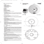
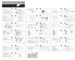
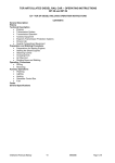
User manual Puma Compact User manual Puma Compact First, we congratulate you on the purchase of your “Jonge Poerink Conveyors” conveyor. A conveyor resulting from 75 years of experience, high standard technology and a wide practical knowledge. Important: Please read this user manual carefully before you start working on or with your Jonge Poerink conveyor. Jonge Poerink Conveyors B.V., nor his legal representatives, can be held responsible for any damage on and/or caused by the Jonge Poerink conveyors as a result of not following the instructions in the user manual. All Jonge Poerink conveyors are designed and produced according to the directions for machine safety by the EEC. (2006/42/EG). Disclaimer The information contained in this user manual is provided only as an aid and service to our customers. Jonge Poerink Conveyors B.V. does not warrant the accuracy or applicability of such information. Jonge Poerink Conveyors B.V. is specifically not responsible for property damage and/or personal injury, direct or indirect for damages and/or failures caused by improper machine design, application, installation, operation, abuse and/or misuse of its products whether or not based on information contained herein. Jonge Poerink Conveyors B.V. does not warrant that the design and/or operational function of any machine that incorporates, and/or intends to incorporate Jonge Poerink Conveyors B.V. products, conforms to any local, state, and/or federal regulations and standards relating to public safety, worker safety, safety guards, sanitation safety, fire safety, or any other safety regulations. ALL PURCHASERS AND USERS SHOULD CONSULT THEIR APPROPRIATE LOCAL, STATE AND FEDERAL REGULATIONS AND STANDARDS © Jonge Poerink Conveyors b.v. 03-03-2010 Contents 1. Do’s and don’ts 2. Installation 2.1 Handling and locating 2.2 Adjusting height and stabling 2.3 Connecting power source 2.4 Safety guards 3. Use 4. The conveyor 4.1 To dismantle the conveyor 4.2 To rebuild the conveyor 5. Conveyor Belt 5.1 To dismount the belt 5.2 To mount the belt 6. Maintenance 6.1 Transmission chains and chain wheels 6.2 Bearing units and support rollers 6.3 Maintenance belt 6.4 Cleaning the system 7. Guarantee 8. Spare part drawing 8.1 JP Puma Compact spare parts list 8.2 Order new spare parts 1. Do’s and don’ts Do not Do Do not start the conveyor when the underground is not stable. Assure that the conveyor is fully stable. Correct differences in floor level with the adjustments on the support legs. Do not work at the electric system when the electric supply is switched on. Switch off the electric supply before carrying out installation work. Do not operate the system when rods are not properly in place. Assure proper fitting of all rods before starting the system (especially after fitting/maintenance of the belt.) Do not operate when belt is damaged. Assure that belt is in good condition. Do not use the conveyor for transport of people or pets. Use the conveyor only for transport of products. The Puma Compact is the ideal conveyor for the food processing industry. Do not start running the belt before checking critical point of operation. - Assure proper running of the belt. Assure proper aligning of drums Assure proper function of the support rollers Assure proper leveling of the belt support Prevent catching points Prevent dragging against framework Check slow-start – slow-stop function. Do not Do Do not overload the belt. Assure that the belt is loaded up according specifications purchased. Do not use chemicals such as chlorides, acids, etc. for cleaning the belt. Follow cleaning agent guidelines as mentioned described in the manual at chapter 6.4. Do not expose the belt to extreme temperatures or to open flame. Keep ignition sources away from the belt (see also ‘Fire safety warning’). Assure good grounding of the installation. Do not expose the belt to product temperatures above 60°C. Keep product in temperature range according specifications purchased. Do not walk on the conveyor. Keep the conveyor clean and prevent belt damage. Do not use the conveyor before protection devices are fitted. First fit the protection device before running. 2. Installation 2.1 Handling and locating Use a forklift with extended forks for easy handling and locating of your conveyor. The most suitable lifting point for your conveyor is under the frame of the conveyor. 2.2 Adjusting height and stabling Once the conveyor is in it’s final position, the differences in floor level can be corrected by means of the adjustments on the support legs. Firstly loosening the lock nut and turn the foot into the correct position. When the conveyor is at the correct height and is fully stable, tighten the lock nut. 2.3 Connecting power source The conveyor can be delivered with a motor. For connecting the motor to a power source, the cover has to be removed (option). The schedule of the electrical connecting details is enclosed, supplied by the manufacturer of the motor. Installation work has to be supplied by a qualified electrician. Check the slow-start – slow-stop function. For a long belt life do not use the conveyor when the slow-start slow-stop function is not connected to the motor. Note: the motor can only turn one direction. The motor may only pull the belt and absolutely not push the belt. Important: before any installation work is carried out, the electrical supply must be switched off! Keep in mind that for maintenance or repairs, the motor has to disconnect easily for the electrical supply. That’s why there should be disconnecting capabilities. 2.4 Safety guards For your safety the conveyor has several safety guards (unless explicitly forbidden by customer). There are no safety guards fitted on the in and out feed to avoid interference of the conveyor. We advise to mount fitting a safety guard to prevent catching from the conveyor belt(s). The conveyor is now ready for use. 3. Use “Jonge Poerink Conveyors” conveyors are designed to be used for the transport of various sized components. If you want to use these conveyors for another purpose and there are doubts about the application, please do not hesitate to contact Jonge Poerink Conveyors. Tel: +31-(0) 74 255 7430 or your agent. We will be happy to discuss your particular application. Warning: The conveyor is not meant to be used for the transport of people or pets. Under no circumstances should you walk or cross the belt during operation. All protection devices must be fitted before operating the conveyor. The A-weighted emission sound pressure level at workstations does not exceed 70dB(A). The peak C-weighted instantaneous sound pressure value at workstations does not exceed 63 Pa. The A-weighted sound power level emitted by the machinery does not 80 dB(A). 4. The conveyor 4.1 To dismantle the conveyor Before dismantling Take the conveyor out of production and ensure it cannot be started during fitting time (isolate electrical supply). To remove the drive The conveyor has a chain transmission drive. Remove chain guard and remove chain. Loosen grub screw(s) of the sprocket on the head shaft and remove sprocket. The conveyor has a shaft mounted geared motor. First disconnect the electrical wiring (to be carried out only by qualified personnel). Remove guard on gearbox, then remove retaining bolt from end of head shaft. Remove bolt connecting torque arm to conveyor frame. Be aware that the geared motor can turn due to it’s own weight. The geared motor can now be pulled of the shaft. To remove the conveyor belt Loosen the bolts on the bearings for both drive and return drums and set them back to give the belt as much slack as possible. Remove belt in accordance with instructions in chapter 5. To remove the drums Remove plastic cover on bearing units, using a screwdriver. Loosen screws in the bearing locking rings and remove locking rings using a hammer and a bar drift. Remove bearing fixing bolts. The bearings can now be removed from the shafts. Careful use of a plastic headed hammer is allowed if necessary. The drums can now be removed from the conveyor. Make a note or sketch showing the exact position of each sprocket (and spacer bushes) on the shaft with all necessary dimensions. After the removal of the fixing the sprockets can be pulled off the shafts. If the shafts are to be re-used, do not remove the sprockets. The shafts may only be drilled once per sprocket, for strength reasons. To remove the supports The steel support rails are not removable. Only very abrasive conditions can cause complete wear. If however the supports have to be replaced, contact Jonge Poerink Conveyors or your agent for advice. The bearings in the lower part can be easily replaced by loosing the bolt and nut connection. If they are undamaged the shafts should be save, as they will be needed for mounting the new bearings. Please remember how the bearings were fitted on the supports. Guides The side guide is made up from bearings mounted in a plastic housing. The plastic housing is held in position by a socket cap screw, which screws into a pop-nut fixing and can be removed without danger. The housing is held to the frame at the bottom by a lip. After removing the bolt, move the upper part of the housing away from the frame and lift the housing upward, releasing the lip from the frame. The bearings are fixed on special bearing plates and have to be exchanged as a complete unit. Before removing the plates, mark the positions of the slotted holes for future reference. 4.2 To rebuild the conveyor First check all parts to be re-used for signs of wear. See chapter 6 ‘Maintenance’. New parts can be ordered, using the spare parts list. See chapter 8. All parts and connection surfaces should be cleaned before fitting. Guidance Fit the guides by placing the bearing plates with the bearing into the housing on the marked places. The straight plate with the bearing mounted on top is placed in the upper part of the housing and guides the top belt strand. The bent plate, with bearing mounted underneath is placed in the lower part of the housing and guides the bottom belt strand. Mount the housing on the frame by sliding the lip of the housing in the slotted hole in the frame and tighten the socket cap screws. Support For conveyors fitted with support bearings in the lower part, mount the bearing with shaft on the special brackets fitted to the cross member supports. Fit in the same way as they were originally fitted. Fitting the drums Drums with plastic sprockets: Push the (new) sprockets (and spacer bushes) on the shaft in exactly the same way as they were originally mounted. Secure the sprockets by means of a retaining ring. Check the position of the sprockets with the belt. The tooth of the sprocket must be situated exactly in the middle, between the ribs of the belt. Place the drum into the frame and fit the bearings. Tighten the bearing units temporary in their most backward position. To fit the conveyor belt See chapter 5 ‘Conveyor belt’. Tensioning the belt Positively driven belts (=by means of toothed drums) do not need to be pretensioned. A small ‘sag’ behind the drive drum, is in most cases even advisable to reduce wear. Check that the belt is laying correctly and flat in the frame. Check again if the positions of the teeth of the drum are correct with the belt. Moving the shaft in the bearings can make any necessary adjustment. Lock the shafts in the bearings using the locking rings; these should be tightened using a light hammer and bar drift. Tighten the setscrews. The teeth of the sprockets must still be in the center of the ribs in the belt. Tension the belt by moving the bearings of the drive and return drums outward by an equal amount, the tension on both sides of the belt should be the same. When belt tension is correct, tighten bearings to frame. Check again that the belt is laying correct and flat on the conveyor and cannot catch on anything. With slow running conveyors and conveyors with adjustable speed, the drive unit can now be fitted. Also fit any guards to avoid possible injury. With a fast running conveyor, i.e. faster than 5 m/min., a crank arm should be fitted to the drive shaft. Run the conveyor by means of the drive motor or crack arm. Motors with adjustable speed should be set at its lowest speed. Check if the belt runs smoothly and does not catch anywhere and that it stays flat on the conveyor. Check if the belt doesn’t tenting on the infeed of the conveyor. If the belt does tenting you have to remove one panel as described in chapter 5. Make a final check if the position of the teeth in the belt is correct and adjust if necessary. Final fitting. Complete fitting of all parts that have been removed from the conveyor. Ensure that all guards and other safety features are present and correctly fitted. 5. Conveyor Belt The Puma Compact is equipped with the JP Plastic Panel belt. rod through the belt from the outside radius, until it touches the screw. 5.1 To dismount the belt Take the conveyor out of production and ensure it cannot be started during fitting time (isolate electrical supply). To replace the existing belt, first release the belt tension by moving back the bearings, see chapter 4 ‘The Conveyor’. To split the belt it is necessary to remove a cross rod. For conveyors with side guides, a slotted hole is provided in both sides of the frame to make this possible. For conveyors without, or with low side guides, placing a steel plate or thin wooden plank under the belt makes the operation of removing a cross rod easier. The rods are locked with two socket cap screw: one on the inside and one on the outside of the belt Remove the socket cap screw of one rod. Remove the rod. Ensure the belt ends cannot slip away because of its weight. The belt can now be removed from the conveyor frame. The belt can now be tensioned, see chapter 4. 5.2 To mount the belt Lay the belt upside down with the ribs uppermost and slide the belt through the lower part of the frame, to the other end of the conveyor. Place both ends of the belt on the upper part and join together by pushing a cross rod in from the outside radius of the belt. Use only straightened wire for the cross rods. Bent or deformed rods may effect the belt performance. For belts without reinforced inner panels, the cross rod is retained in position by inserting an M5x6 screw into the inside radius panel. Ensure the head of the screw is a minimum of 1 mm inside the panel. Push the cross Warning – Fire Safety Precautions for Hybrid and Plastic Belting Puma Compact (Poly Amid, TPU or POM) belts contain thermoplastic components and can burn. If exposed to an open flame or to temperatures above state Puma Compact (Poly Amid, TPU or POM) specifications, these belts may decompose and emit toxic fumes. Do not expose the Puma Compact (Poly Amid, TPU or POM) belts to extreme temperatures or to open flame. Additionally, these belts should also not be used following any process, such as an oven, where products could be ignited before being placed on the belt. Refer to the appropriate MSDS (Material Safety Data Sheet) for other precautions and emergency response information. 6. Maintenance 6.1 Transmission chains and chain wheels After the first 40 hours running all transmission chains must be adjusted and after every 100 hours running they should be lubricated. When any wear is clearly visible both chain and chain wheels should be replaced. 6.2 Bearing units and support rollers All bearings units and support rollers are fully sealed and lubricated for life. When the bearings show signs of wear such as looseness in the tolerance or do not run freely, they should be replaced. When the teeth of the drums show wear they should be replaced. Support and guide strips must be replaced when wear is clearly visible and must always be replaced when fitting a new belt. 6.3 Maintenance belt Use only straightened wire for the cross rods. Bent or deformed rods may effect the belt performance. Normal cleaning of the belt is sufficient. The belt can be cleaned under high pressure with water or (non aggressive) cleaning liquid. Also steam cleaning is permitted if not used for too long a period (only the material POM blue is resistant against high temperature in combination with the influence of water and can be steamed without limit). Rinse the conveyor/belt always with water after cleaning. After every 1.000 hours the belt has to be checked on tenting on the infeed of the conveyor. If the belt does tenting, you have to remove one panel as described in chapter 4. 6.4 Cleaning the system Normal cleaning of the conveyor is sufficient. The conveyor can be cleaned under high pressure with water and (non aggressive) cleaning liquid. Even steam cleaning is permitted on conveyors that do not have a painted finish. Take care not to spray on to the bearings, chain transmission and motors, because the possibility exists that lubricant is washed away, resulting in a build up of rust, inefficient operating and the danger of an electrical short circuit. Rinse the conveyor/belt always with water after cleaning. 7. Guarantee Damage during transport must be reported within one working day to: Jonge Poerink Conveyors Borne – Holland Tel. +31-(0)74 255 7430 Email: [email protected] All our transactions are subject to our most recent general conditions of sale, delivery and payment as deposited with the District Court of Almelo, the Netherlands. On request a copy will be sent free of change. 8. Spare part drawing 8.1 JP Puma Compact spare parts list 1. 2. 3. 4. 5. 6. 7. Panel belt Flanged bearing Drive assembly, complete Sprocket Tail assembly, complete Side guidance Belt support rollers 8.2 Order new spare parts Spare parts to be ordered at: Jonge Poerink Conveyors BV Industriestraat 6b P.O. box 4, 7620 AA Borne The Netherlands Tel. +31 (0) 74 255 7430 www.jpcconveyors.com Or your agent. Please state with the order: Type, serial number, name, drawing position number or code of the part to be ordered. These dates can be found on the serial type plate. These dates can be found on the serial type plate.