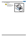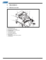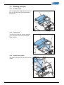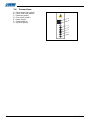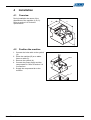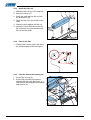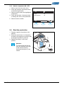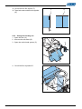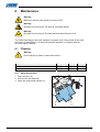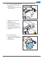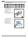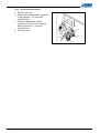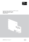
1
User Manual
EasyBagger
© All rights reserved
The information provided in this manual may not be reproduced and / or published in any form, by print, photoprint,
microfilm or any other means whatever (electronically or mechanically) without the prior written authorisation of
JASA Packaging Systems.
2
User Manual
Table of contents
User Manual............................................................................................................... 1
EasyBagger ............................................................................................................. 1
1
Introduction......................................................................................................... 5
1.1 Intended use .................................................................................................. 5
1.2 Identification plate .......................................................................................... 5
2
Safety................................................................................................................... 6
2.1 Safety signs ................................................................................................... 6
2.1.1 Safety signs in the manual and on the machine.......................................6
2.1.2 Position of safety signs and emergency stop on the machine..................6
2.1.3 Protection cover........................................................................................7
3
Description.......................................................................................................... 8
3.1 Machine overview .......................................................................................... 8
3.2 Working principle ........................................................................................... 9
3.2.1 In-feed system ..........................................................................................9
3.2.2 Forming set...............................................................................................9
3.2.3 Vertical seal system..................................................................................9
3.2.4 Horizontal seal system ...........................................................................10
3.3 Control panel................................................................................................ 11
3.3.1 Main control ............................................................................................11
3.3.2 Process control.......................................................................................11
3.4 Connections ................................................................................................. 12
4
Installation......................................................................................................... 13
4.1 Overview ...................................................................................................... 13
4.2 Position the machine.................................................................................... 13
5
Operation........................................................................................................... 14
5.1 Safety devices.............................................................................................. 14
5.1.1 Emergency stop......................................................................................14
5.1.2 Door........................................................................................................14
5.2 Prepare for production ................................................................................. 15
5.2.1 Open the seal area .................................................................................15
5.2.2 Attach the forming set.............................................................................15
5.2.3 Install the film roll....................................................................................16
5.2.4 Feed in the film .......................................................................................16
5.2.5 Feed the film to the forming set ..............................................................16
5.2.6 Lock the vertical seal system..................................................................17
5.2.7 Adjust the vertical seal system ...............................................................17
5.3 Start up the machine .................................................................................... 18
5.3.1 Set main control......................................................................................18
5.3.2 Set production settings ...........................................................................18
5.3.3 Switch components ON / OFF................................................................19
5.4 Start the production...................................................................................... 19
5.5 Changes during production .......................................................................... 20
5.5.1 Change the film roll.................................................................................20
5.5.2 Change the forming set ..........................................................................21
6
Maintenance...................................................................................................... 24
6.1 Cleaning....................................................................................................... 24
6.1.1 Open the seal area .................................................................................24
User Manual
3
6.1.2 Clean the seal jaws and the knife...........................................................25
6.1.3 Close the seal area.................................................................................25
6.2 Technical maintenance ................................................................................ 26
6.2.1 Replace the knife....................................................................................26
6.2.2 Replace the film wheels..........................................................................26
6.2.3 Check the air pressure ...........................................................................27
4
7
Troubleshooting ............................................................................................... 28
7.1 Test of the electrical devices........................................................................ 28
7.2 Error messages............................................................................................ 29
7.3 Product problems ......................................................................................... 30
8
Appendix ........................................................................................................... 31
8.1 Default configuration settings....................................................................... 31
8.2 Technical specifications ............................................................................... 34
8.3 Product specifications .................................................................................. 34
8.4 Additional information .................................................................................. 34
8.4.1 Certification.............................................................................................34
8.4.2 Guarantee...............................................................................................34
8.4.3 Disposal..................................................................................................34
User Manual
1
Introduction
This manual is intended for operators and service personnel of the EasyBagger form, fill
and seal machine. For product and technical specifications refer to chapter 8: Appendix.
1.1
Intended use
The JASA EasyBagger is designed to pack small runs of various products into
flexible packs.
Warning
The use of the machine other than above mentioned is to be regarded as
non-intended use, unless it is previous approved off in a written statement
by JASA Packaging Systems.
1.2
A
B
C
D
E
F
G
H
Identification plate
Type number
Machine number
Year of production
Serial number
Power consumption
Electrical requirements
Air pressure
Air consumption
A
C
D
Hazenkoog 14
1822 BS Alkmaar
tel.: 072-5612700
fax.: 072-5625407
Ty p e
BJ
M a c h . n r.
Serie
Phase
Air
V
Kw
L t r. / m i n .
H
User Manual
B
Bar
G
A
F
E
5
2
Safety
Read this manual before operating the machine.
2.1
Safety signs
2.1.1 Safety signs in the manual and on the machine
Risk of a hazard that can
cause death or serious
injury
Additional information
Risk of electric shock
Hot
Risk of injury by moving
parts
GENCY STO
ER
P
EM
Emergency stop
2.1.2 Position of safety signs and emergency stop on the machine
•
•
Do not cover or remove the signs on the machine.
Replace the signs that are damaged or not legible.
GENCY STO
ER
P
EM
6
User Manual
2.1.3 Protection cover
Warning
Do not remove the
protection cover. The knife
behind the protection cover
is very sharp edged and can
cause serious injury.
User Manual
7
3
Description
3.1
Machine overview
B
A
C
D
J
E
I
H
A
B
C
D
E
F
G
H
I
J
8
G
F
Packaging film roll
Filling tube (forming set)
Forming shoulder (forming set)
Control panel
Vertical seal system
Foot switch (option)
Horizontal seal system
Main switch
Support frame with wheels (option)
Connections
User Manual
3.2
Working principle
3.2.1 In-feed system
The in-feed system leads the film from the
film roll (A) via guide rollers towards the
forming set.
A
3.2.2 Forming set
The film is led over the forming shoulder
(A) to produce a tube form around the
filling tube (B).
A
B
3.2.3 Vertical seal system
The vertical seal jaw (A) seals the film into
a tube.
A
User Manual
9
3.2.4 Horizontal seal system
The horizontal seal jaws (A) create a seal
and the knife (B) cuts the seal in the
middle, to create a bottom seal and a top
seal. The result is a filled and a closed bag.
The horizontal seal system has two
functions:
1. To close the filled bags.
2. To catch the products when the
horizontal seal jaws are closed.
A
B
10
User Manual
3.3
Control panel
3.3.1 Main control
A Main switch
B Compressed air control
A
B
ON
0.4
0.6
0.2
OFF
0
0.8
MPa
1.0
3.3.2 Process control
A
B
C
D
E
F
G
Emergency stop
Decrease / increase value or position
Select display functions
Manual film transport options
Stop
Start
Display
F
G
A
GENCY STO
ER
P
EM
START
E
STOP
D
C
B
Display functions
Enter
↵
←→
Open film transport wheels
↓↓
Start / stop transport wheels
→←
Close film transport wheels
→
Move cursor one position
PROG
Choose program / Edit
settings
RESET
Reset
TEST
Test electronic inputs /
outputs
PASSW
Enter password
SERVICE
Get production information
ESC
Go to previous screen
Service menu
COMP
Switch components ON / OFF
Advanced settings
OK
OK
User Manual
11
3.4
A
B
C
D
E
F
G
Connections
Printer black tube (option)
Printer blue tube (option)
Photocell (option)
Foot switch (option)
Power supply
Compressed air
Synchro (option)
A
ZWART
B
BLAUW
C
D
E
F
G
12
User Manual
4
Installation
4.1
Overview
During installation be aware of the
dimensions of the machine (A, B, C).
Refer to section 8.2 Technical
specifications.
B
C
A
4.2
Position the machine
1. Connect the hoist cable to the eyebolt
(A).
2. Place the machine (B) on a stable
frame or table (C).
3. Remove the eyebolt (A).
4. Connect the power supply and the
compressed air. Refer to section 3.4
Connections.
5. Supply the compressed air to the
machine.
A
B
C
User Manual
13
5
Operation
5.1
Safety devices
5.1.1 Emergency stop
1. Push the emergency stop (A) in an
emergency. The power supply and the
compressed air will be interrupted
immediately.
2. Find the cause of the interruption.
A
GENCY STO
ER
P
EM
START
Warning
Do not reset, until the reason
is found why the emergency
stop has been pushed.
CLEAR EMERGNCY
STOP
STOP
3. Pull the emergency stop to clear the
emergency stop.
4. Select RESET.
5.1.2 Door
1. Close the door before the start of the
production.
2. Select RESET.
CLOSE DOOR
PRESS RESET
RESET
14
User Manual
5.2
Prepare for production
Warning
Make sure that the main switch is turned to OFF.
5.2.1 Open the seal area
1. Open the door (A).
2. Unscrew the star knob (B).
3. Open the vertical seal system (C).
C
B
A
5.2.2 Attach the forming set
1. Attach the forming set (A).
2. Fasten the star knobs (B).
User Manual
A
B
15
5.2.3 Install the film roll
1. Attach the film roll (A) to the shaft (B).
2. Attach the cones (C).
3. Install the shaft with the film roll into
the suspension (D).
4. Place the film roll in the middle of the
shaft.
5. Slide the cones against the film roll.
6. Attach the cones with the screws (E).
Be sure there is no play between the
film roll and the shaft.
A
B
C
E
D
5.2.4 Feed in the film
1. Feed the film via the guide rolls along
the indicated path to the forming set.
5.2.5 Feed the film to the forming set
1. Cut the film to a tip (A).
2. Pull the film manually through the
shoulder (B) along the filling tube (C)
until the film has passed the horizontal
seal system (D).
B
C
D
A
16
User Manual
5.2.6 Lock the vertical seal system
1. Close the vertical seal system (A).
2. Lock the vertical seal system with the
star knob (B).
A
B
5.2.7 Adjust the vertical seal system
1. Loosen the star knobs (A).
2. Set the vertical seal jaw (B) to a
distance of 5 mm to the filling tube (C).
3. Fasten the star knobs (A).
4. Close the door (D).
A
C
B
D
A
User Manual
17
5.3
Start up the machine
5.3.1 Set main control
1. Turn the main switch (A) to ON.
2. Read out the value of the compressed
air on the indicator (B).
3. Pull and rotate the knob (C) to set the
value of the compressed air to 6 bar.
4. Select RESET.
5. Close the transport belts.
A
B
C
ON
0.4
0.6
0.2
OFF
0
0.8
MPa
1.0
5.3.2 Set production settings
1. Select PROG to go to the programming
menu.
23°C
22°C
PROG 1
21°C
COMP
2. Press the decrease / increase button
to scroll through the entire menu.
3. Select ENTER to select the highlighted
parameter.
4. Press the decrease / increase button
to change the value of the parameter.
5. Select ENTER to confirm.
6. For default configuration adjustments
refer to section 8.1 Default
configuration settings.
18
PROG
Program Nr
TEMP
1
T horizontal seal front 140 °C
T horizontal seal front 140 °C
T horizontal seal front 140 °C
Time horizontal seal
0.75 s
ESC
User Manual
5.3.3 Switch components ON / OFF
1. Select COMP from the main menu.
2. Press the increase / decrease button
to scroll through the list.
3. Select ENTER to select the highlighted
component.
4. Press the decrease / increase button
to change the value of the parameter.
5. Select ENTER to confirm.
Gas
off
Printer
off
(Hot) perforator
off
ESC
5.4
Start the production
1. Prepare a portion of products to be
packed.
2. Press the start button A or footswitch
B (option) and supply the machine with
the prepared portion of products.
3. Repeat from step 1 for the next
portions.
A
Attention
To prevent that the film will
tear, the products must land
at the moment that the
horizontal seal jaws (C) are
closed.
User Manual
B
C
19
5.5
Changes during production
5.5.1 Change the film roll
1. Remove the shaft (A) from the
suspension (B).
2. Loosen the screws (E).
3. Remove the cones (C).
4. Remove the empty film roll (D) from
the shaft.
D
A
C
E
B
5. Place the film roll (D) on the shaft (A).
6. Place the cones (C).
7. Place the shaft with the film roll into
the suspension (B).
8. Position the film roll in the middle of
the shaft.
9. Slide the cones against the film roll.
10. Fix the cones with the screws (E). Be
sure there is no play between the film
roll and the shaft.
D
A
C
E
B
11. Feed the film via the guide rolls along
the indicated path to the forming set.
20
User Manual
12. Cut-off the new film square (F).
13. Tape both ends wrinkle-free together
(G).
F
G
5.5.2 Change the forming set
1. Open the door (A).
2. Unscrew the star knob (B).
3. Open the vertical seal system (C).
C
B
A
4. Cut-off the film at position D.
D
User Manual
21
5. Remove the star bolts (E) and remove
the forming set (F).
6. Attach an other forming set in opposite
order.
E
F
7. Cut the film to a tip (G).
8. Pull the film manually through the
shoulder (H) along the filling tube (I)
until the film has passed the horizontal
seal system (J).
H
I
J
G
9. Close the vertical seal system (K).
10. Lock the vertical seal system with the
star knob (L).
K
L
22
User Manual
11. Loosen the star knobs (M).
12. Set the vertical seal jaw (N) to a
distance of 5 mm to the filling tube (O).
13. Fasten the star knobs (M).
14. Close the door.
M
O
N
M
User Manual
23
6
Maintenance
Warning
Make sure that the main switch is turned to OFF.
Warning
Be aware for hand injury! The knife is very sharp edged.
Warning
Be aware for hand injury! The seal jaws and the knife can be hot.
The JASA Easy Bagger has been designed to operate over a long period of time with
a minimum of maintenance. Continuous operation depends on a proper machine
care and regular cleaning.
6.1
Cleaning
Warning
Do not spray any water to clean the machine.
Inspection
Seal jaws
Knife
Frequency
Daily
Daily
Action
Clean
Clean
See
6.1.1
6.1.1
6.1.1 Open the seal area
1. Open the door (A).
2. Unscrew the star knob (B).
3. Open the vertical seal system (C).
C
B
24
A
User Manual
6.1.2 Clean the seal jaws and the knife
1. Clean the aluminium parts with a
wooden tongue.
2. Clean the stainless steel seal jaw (A)
with a brass brush.
A
3. Release the spring (B) from the
bracket (C).
4. Remove the knife (D).
5. Clean the knife with a filling knife.
6. Clean the stainless steel seal jaws
with a brass brush.
7. Place the knife in opposite order.
8. Grease the horizontal seal jaw at the
element side.
B
C
D
6.1.3 Close the seal area
1. Close the vertical seal system (A).
2. Lock the vertical seal system with the
star knob (B).
3. Close the door (C).
A
B
User Manual
C
25
6.2
Technical maintenance
Inspection
Knife
Film
wheels
Air
pressure
Check
Severe contamination or damage
Worn out of the rubber
Frequency
Daily
Weekly
Action
Replace
Replace
See
6.2.1
6.2.3
Required values
Half-yearly
Adjust
6.2.4
6.2.1 Replace the knife
1. Open the seal area. Refer to section
6.1.1: Open the seal area.
2. Release the spring (A) from the
bracket (B).
3. Remove the knife (C).
4. Place the new knife in opposite order.
5. Close the seal area. Refer to section
6.1.3: Close the seal area.
A
B
C
6.2.2 Replace the film wheels
1. Open the seal area. Refer to section
6.1.1: Open the seal area.
2. Unscrew the bolts (A).
3. Remove the film wheels (B).
4. Install the new film wheels.
5. Tighten the bolts.
6. Close the seal area. Refer to section
6.1.3: Close the seal area.
A
B
26
User Manual
6.2.3 Check the air pressure
1. Remove the cover.
2. Read out the compressed air pressure
at the indicator 1 (A) and at the
indicator 2 (B).
3. Adjust the airpressure with the
regulators (C) and (D), if necessary.
Refer to section 8.1: Technical
Specifications.
4. Place the cover.
D
B
C
A
User Manual
27
7
Troubleshooting
Warning
Be aware for hand injury! The knife is very sharp edged.
Warning
Be aware for hand injury! The seal jaws and the knife can be hot.
7.1
Test of the electrical devices
To test the electrical devices on the machine go to the TEST screen.
1.
2.
3.
4.
Press password.
Enter password (1112).
Go to the screen TEST INPUTS.
Activate the input device that has to be
tested.
5. Check the change of state of the
activated input.
6. Select ESC to leave the test screen.
7. Go to the screen TEST OUTPUTS.
8. Press the increase / decrease button
to scroll through the entire list.
9. Press TEST to toggle the desired
output.
10. Select ESC to leave the test screen.
28
User Manual
7.2
Error messages
Number
0
Name in software
ERR__NONE
Description
No errors
1
ERR_TEMPLOW
Temperature too low
2
ERR_TEMPHIGH
Temperature too high
3
ERR_HEATER
Heater error
4
ERR_SEALCLOSE
Horizontal seal close error
5
ERR_SEALOPEN
Horizontal seal open error
6
ERR_FILMADJ
Film adjust exceeds limits
7
ERR_FILMMOVE
Timeout during film move
8
ERR_CONFIG
Configuration could not be restored
9
ERR_PRODDETNONE
No product detected, stopped
10
ERR_PRODDETMAX
Too much product detected, stopped
11
ERR_MARKERMAX
Marker position exceeds maximum
12
ERR_PRINTER
Printer error
13
ERR_NOFILM
No film detected
14
ERR_IO_COMM
No communication with IO-board
15
ERR_IO_24V
IO-board 24V not ok
16
ERR_IO_L1
Mains input phase L1 not ok
17
ERR_IO_L2
Mains input phase L2 not ok
18
ERR_IO_L3
Mains input phase L3 not ok
19
ERR_IO_PT1
Temperature sensor 1 not ok
20
ERR_IO_PT2
Temperature sensor 2 not ok
21
ERR_IO_PT3
Temperature sensor 3 not ok
22
ERR_FR_COM
No communication with FR-board
23
ERR_FR_PSU
FR-board power supply not ok
24
ERR_FR_CURR
Transport motor current too high
25
ERR_FR_TEMP
FR-board temperature too high
26
ERR_FR_TMOT
Transport motor temperature too high
27
ERR_FR_IXT
Transport motor overload detected
28
ERR_FR_NOCURR
Transport motor current too low
User Manual
29
7.3
Product problems
Problem
Horizontal seal not
closed
The bag is not cut off
Possible cause
The seal jaws are not fully
closed
The temperature is too low
The seal time is too short
The vertical seal jaw does
not reach the filling tube
The temperature is too low
The seal time is too short
Film is creased on the
vertical seal
The distance between the
vertical seal jaw and the
filling tube is too short
The film transport does not
stand still at the moment
that the vertical seal is
activated
The knife is caked
The bag length fluctuates
The mark detection is OFF
Set the mark detection to
ON
No print on the bag
The printer is OFF
Set the printer to ON
Vertical seal not closed
Bag tears on vertical seal
seam
30
Action
Adjust the seal jaws
Increase the temperature
Increase the seal time
Adjust the vertical seal
jaw
Increase the temperature
Increase the seal time
Smooth down the film
Adjust the vertical seal
jaw
Decrease the deceleration
time
Clean the knife
User Manual
8
Appendix
8.1
Default configuration settings
Menu
User settings:
Description
Default
Unit
MNU_TEMP
Program number
1
MNU_TEMP
Temperature horizontal seal front
140
°C
MNU_TEMP
Temperature horizontal seal rear
140
°C
MNU_TEMP
Temperature vertical seal
140
°C
MNU_TEMP
Time horizontal seal
0,75
s
MNU_TEMP
Time vertical seal
0,4
s
MNU_TEMP
Cool pulse time
0,2
s
MNU_PROG
Film length
250
mm
MNU_PROG
Wait before transport
1
s
MNU_PROG
Wait after package
1
s
MNU_PROG
No drop in a bag
1
X
MNU_PROG
Earlier drop moment
0
s
MNU_PROG
Film tracking pulse time
0,3
s
MNU_PROG
Perforator time
0,1
s
MNU_PROG
Bag length sensor delay
0,05
s
MNU_PROG
Pulse gas time
0,1
s
MNU_PROG
Continuous gas time
1
s
MNU_PROG
Pre gas time
0,5
s
MNU_COMP
Gas
Off
MNU_COMP
Printer
On
MNU_COMP
(Hot) perforator
Off
MNU_COMP
Bag length detection
Off
MNU_COMP
Mark detection
Off
MNU_COMP
Film tracking
Off
MNU_COMP
Bag vibrator
Off
MNU_COMP
Side infold
Off
MNU_COMP
Block bottom
Off
MNU_COMP
Counter
Off
Components:
User Manual
31
Menu
MNU_SERV
Description
Bags packed today
Default
0
MNU_SERV
Bags packed total
0
MNU_SERV
Hours total
0
MNU_SERV
Software revision
-
MNU_SERV
Test inputs
-
MNU_SERV
Test outputs
-
MNU_SERV
Machine settings
-
Unit
Machine settings:
32
MNU_INST
Language
English
MNU_INST
Film length factor
400
mm/s
MNU_INST
Motor speed
50
Hz
MNU_INST
Acceleration
0,1
s
MNU_INST
Deceleration
0,1
s
MNU_INST
Maximum temperature error
10
°C
MNU_INST
Maximum horizontal close time
800
ms
MNU_INST
Length vertical seal
220
mm
MNU_INST
Printer type
none
MNU_INST
Printer error contact
none
MNU_INST
Film transport type
Timer
MNU_INST
Synchro type
none
MNU_INST
Seal type
Heat-seal
MNU_INST
Seal horizontal front
On
MNU_INST
Seal horizontal rear
On
MNU_INST
Seal vertical
On
MNU_INST
Pulse gas
not available
MNU_INST
Continuous gas
not available
MNU_INST
Perforator type
not available
MNU_INST
Bag length detection
not available
MNU_INST
Mark detection
not available
MNU_INST
Film tracking
not available
MNU_INST
Film tracking sensor
left
MNU_INST
Bag vibrator
not available
MNU_INST
Side infold
not available
MNU_INST
Block bottom
not available
MNU_INST
System configuration
-
User Manual
Menu
MNU_CONF
Description
Machine type
Default
Easybagger
MNU_CONF
Ethernet IP address
192.168.1.147
MNU_CONF
Ethernet netmask
255.255.255.0
MNU_CONF
Ethernet gateway
192.168.1.39
MNU_CONF
Ethernet MAC address
-
MNU_CONF
System CAN nodes
-
MNU_INP
IN1: seal open
-
MNU_INP
IN2: seal closed
-
MNU_INP
IN3: printer in
-
MNU_INP
IN4: mark detection
-
MNU_INP
IN5: synchro in
-
MNU_INP
IN6: film sensor L
-
MNU_INP
IN7: film sensor R
-
MNU_INP
IN8: film end L
-
MNU_INP
IN9: film end R
-
MNU_INP
IN10: film detection
-
MNU_INP
IN11: reserve 1
-
MNU_INP
IN12: reserve2
-
MNU_INP
IN13: reserve 3
-
MNU_INP
IN14: reserve 4
-
MNU_INP
IN15: emergency
-
MNU_OUTP
OUT1: seal horizontal
Off
MNU_OUTP
OUT2: seal knife
Off
MNU_OUTP
OUT3: seal vertical
Off
MNU_OUTP
OUT4: film belt
Off
MNU_OUTP
OUT5: cooler
Off
MNU_OUTP
OUT6: heat front
Off
MNU_OUTP
OUT7: heat rear
Off
MNU_OUTP
OUT8: heat vertical
Off
MNU_OUTP
OUT9: heat reserve
Off
MNU_OUTP
OUT10: film L
Off
MNU_OUTP
OUT11: film R
Off
MNU_OUTP
OUT12: printer
Off
MNU_OUTP
OUT13: synchro
Off
MNU_OUTP
OUT14: reserve 1
Off
MNU_OUTP
OUT15: reserve 2
Off
User Manual
Unit
33
Menu
MNU_OUTP
Description
OUT16: reserve 3
Default
Off
MNU_OUTP
OUT17: reserve 4
Off
MNU_OUTP
OUT18: reserve 5
Off
MNU_OUTP
Motor film transport
Off
8.2
Technical specifications
Item
Weight
Dimensions
Electrical requirements
Electrical capacity
Air pressure
8.3
Specification
165 kg (incl. forming set)
Length (C) = 1200 mm
Width (B) = 850 mm
Height (A) = 1200 mm
3 phase 400V + N + PE
(1 phase 230 V + N + PE on request)
2500 W
On operator panel: 6 bar
On indicator 1:
4 bar
On indicator 2:
2 bar
Product specifications
Item
Bag width
Bag length
Packaging material
8.4
Unit
Specification
Max. 350 mm
No limit
Polypropylene or laminated film
Additional information
8.4.1 Certification
Refer to the separate CE-declaration that is delivered to the EU-countries.
8.4.2 Guarantee
For information on guarantee refer to the delivery conditions.
8.4.3 Disposal
At the end of life dispose the machine according to the local regulations.
34
User Manual
User Manual
35