1
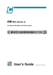
English
USER’S MANUAL
INTONATOR
VOCAL INTONATION PROCESSOR
IMPORTANT SAFETY INSTRUCTIONS
The lightning flash with an arrowhead symbol
within an equilateral triangle, is intended to alert
the user to the presence of uninsulated "dangerous voltage" within the product's enclosure that may
be of sufficient magnitude to constitute a risk of electric
shock to persons.
The exclamation point within an equilateral triangle
is intended to alert the user to the presence of
important operating and maintenance (servicing)
instructions in the literature accompanying the product.
1
2
3
4
5
6
7
Warning!
• To reduce the risk of fire or electrical shock, do not
expose this equipment to dripping or splashing and
ensure that no objects filled with liquids, such as vases,
are placed on the equipment.
• This apparatus must be earthed.
• Use a three wire grounding type line cord like the one
supplied with the product.
• Be advised that different operating voltages require the
use of different types of line cord and attachment plugs.
• Check the voltage in your area and use the
correct type. See table below:
8
9
10
11
12
13
Read these instructions.
Keep these instructions.
Heed all warnings.
Follow all instructions.
Do not use this apparatus near water.
Clean only with dry cloth.
Do not block any ventilation openings. Install in
accordance with the manufacturer's instructions.
Do not install near any heat sources such
as radiators, heat registers, stoves, or other
apparatus (including amplifiers) that produce heat.
Do not defeat the safety purpose of the polarized
or grounding-type plug. A polarized plug has two
blades with one wider than the other. A grounding
type plug has two blades and a third grounding
prong. The wide blade or the third prong are
provided for your safety. If the provided plug does
not fit into your outlet, consult an electrician for
replacement of the obsolete outlet.
Protect the power cord from being walked
on or pinched particularly at plugs, convenience
receptacles, and the point where they exit from the
apparatus.
Only use attachments/accessories specified by the
manufacturer.
Unplug this apparatus during lightning storms or
when unused for long periods of time.
Use only with the cart, stand, tripod, bracket, or
table specified by the manufacturer, or sold with
the apparatus. When a cart is used, use
caution when moving the cart/apparatus
combination to avoid injury from tip-over.
Refer all servicing to qualified service
personnel. Servicing is required when the
apparatus has been damaged in any way,
such as power-supply cord or plug is damaged,
liquid has been spilled or objects have fallen into
the apparatus, the apparatus has been exposed to
rain or moisture, does not operate normally, or has
been dropped.
Voltage
Line plug according to standard
110-125V
UL817 and CSA C22.2 no 42.
220-230V CEE 7 page VII, SR section
107-2-D1/IEC 83 page C4.
240V
•
•
•
•
•
BS 1363 of 1984.
Specification for 13A fused
plugs and switched and
unswitched socket outlets.
This equipment should be installed near the socket
outlet and disconnection of the device should be easily
accessible.
To completely disconnect from AC mains, disconnect
the power supply cord from the AC receptable.
The mains plug of the power supply shall remain
readily operable.
Do not install in a confined space.
Do not open the unit - risk of electric shock inside.
Caution:
You are cautioned that any change or modifications not
expressly approved in this manual could void your authority
to operate this equipment.
Service
• There are no user-serviceable parts inside.
• All service must be performed by qualified personnel.
a
NOTE
EMC / EMI.
This equipment has been tested and found to comply with
the limits for a Class B Digital device, pursuant to part 15 of
the FCC rules.
These limits are designed to provide reasonable protection
against harmful interference in residential installations. This
equipment generates, uses and can radiate radio
frequency energy and, if not installed and used in
accordance with the instructions, may cause harmful
interference to radio communications. However, there is no
guarantee that interference will not occur in a particular
installation. If this equipment does cause harmful
interference to radio or television reception, which can be
determined by turning the equipment off and on. The user
is encouraged to try to correct the interference by one or
more of the following measures:
•
•
•
•
Reorient or relocate the receiving antenna.
Increase the separation between the equipment and
receiver.
Connect the equipment into an outlet on a circuit
different from that to which the receiver is connected.
Consult the dealer or an experienced radio/TV
technician for help.
For the customers in Canada:
This Class B digital apparatus complies with Canadian
ICES-003.
Cet appareil numérique de la classe B est conforme à la
norme NMB-003 du Canada.
Certificate Of Conformity
TC Electronic A/S, Sindalsvej 34, 8240 Risskov, Denmark,
hereby declares on its own responsibility that following product:
Intonator - Digital Vocal Intonation Processor
that is covered by this certificate and marked with CE-label
conforms with following standards:
EN 60065
(IEC60065)
Safety requirements for mains
operated Electronic and related
apparatus for household and similar
general use.
EN 55103-1
Product family standard for audio,
video, audio-visual and entertainment
lighting control apparatus for
professional use.
Part 1: Emission.
EN 55103-2
Product family standard for audio,
video, audio-visual and entertainment
lighting control apparatus for
professional use.
Part 2: Immunity.
With reference to regulations in following directives:
73/23/EEC, 89/336/EEC
Issued in Risskov, June 14th 1999
Anders Fauerskov
Managing Director
b
TABLE OF CONTENTS
INTRODUCTION
APPENDIX
Important Safety Instructions
Table of contents . . . . . . . . . . .
Introduction . . . . . . . . . . . . . . .
Front Panel . . . . . . . . . . . . . . .
Rear Panel . . . . . . . . . . . . . . .
Signal flow diagram . . . . . . . . .
. . . . . a-b
.......3
.......5
.......6
.......8
.......9
MIDI Implementation Chart . . . . . . . . . 26
Technical Specifications . . . . . . . . . . . . 27
Self Test . . . . . . . . . . . . . . . . . . . . . . . 28
Soldering Instructions . . . . . . . . . . . . . 29
Glossary . . . . . . . . . . . . . . . . . . . . . . . 30
BASIC OPERATION
Intonator Setup . . . . . .
Displays and Keyboard
Correction Processing .
Automated Dynamics. .
Custom Scales . . . . . .
Automatic Mode. . . . . .
Manual Mode. . . . . . . .
.
.
.
.
.
.
.
.
.
.
.
.
.
.
.
.
.
.
.
.
.
.
.
.
.
.
.
.
.
.
.
.
.
.
.
.
.
.
.
.
.
.
.
.
.
.
.
.
.
.
.
.
.
.
.
.
.
.
.
.
.
.
.
.
.
.
.
.
.
.
.
.
.
.
.
.
.
.
.
.
.
.
.
.
10
13
14
16
17
17
18
MIDI and Manual mode . . . . . .
MIDI and Automatic mode . . . .
Internal Parameter Bulk Dump .
Front Panel Reset . . . . . . . . . .
.
.
.
.
.
.
.
.
.
.
.
.
.
.
.
.
.
.
.
.
.
.
.
.
20
20
20
20
.
.
.
.
.
.
.
.
.
.
.
.
.
.
.
.
.
.
.
.
.
.
.
.
.
.
.
.
.
.
.
.
.
.
.
.
.
.
.
.
.
.
.
.
.
.
.
.
.
.
.
.
.
.
.
.
.
.
.
.
.
.
.
.
.
.
.
.
.
.
.
.
.
.
.
.
.
.
.
.
.
.
.
.
.
.
.
.
.
.
.
.
.
.
.
.
.
.
.
.
.
.
.
.
.
.
.
.
21
21
21
22
22
23
23
24
24
24
24
24
24
25
25
25
25
25
MIDI
MIDI CONTINUOUS
CONTROLLERS
Overview . . . . . . . . . . . . . . .
Scale selection . . . . . . . . . . .
Pitch Window. . . . . . . . . . . . .
Attack Control . . . . . . . . . . . .
Amount . . . . . . . . . . . . . . . . .
Manual Mode. . . . . . . . . . . . .
Note Hold . . . . . . . . . . . . . . .
Pitch Bypass . . . . . . . . . . . . .
Adaptive Low Cut key . . . . . .
Adaptive Low Cut Filter . . . . .
De-ess key . . . . . . . . . . . . . .
De-ess Control. . . . . . . . . . . .
Correction Amount . . . . . . . . .
Tuning Reference Adjustment
Custom Scale Notes . . . . . . .
Input Pitch . . . . . . . . . . . . . . .
Manual Pitch Bend. . . . . . . . .
Keyboard Notes. . . . . . . . . . .
.
.
.
.
.
.
.
.
.
.
.
.
.
.
.
.
.
.
TC Electronic, Sindalsvej 34, DK-8240 Risskov - [email protected]
English version Rev 2.3 - SW - V 1.01
Prod. No. 606100010
3
INTRODUCTION
Congratulations on the purchase of your TC Intonator.
Why the Intonator ?
In recording, the voice is often referred to as "the money channel". There are a number of different reasons for this label. With pop music,
the lead vocal is considered the key to a song's success. The song and its arrangement can be perfect, but without a great vocal no one is
going to listen to the song. Another reason for that name would be the cost and amount of gear used on vocals. Engineers will take a
second mortgage on their home to get that elusive vocal sound. However, when the focus is put on the word MONEY in "the money
channel", one can not dispute the fact that a lot of time is spent tracking, double tracking, comping, editing, and mixing the voice.
Going with the defacto financial “one liner”: time is money, the amount of money spent on vocals can be staggering.
Though money saved due to less tracking-time spent, is a strong argument for utilizing the pitch correction techniques, a few musical
aspects should also be considered. Very often the strongest energy and timing occurs during the first two or three takes. Further tracking
just to nail a few “out of pitch” notes, often kills the initial energy and fresh feeling. Keep the “good track” and use the Intonator to correct
the few out of pitch notes there might be.
Another example is the situation where repeated tracking is unavoidable, while striving for the perfect vocal take. The result is an
exhausted vocalist. So, the timing and phrasing might be perfected after several takes, but as the vocalist gets tired one of the first skills to
slip is the intonation. Keep the take when only minor intonation problems exists and let the Intonator perfect the track.
These reasons have sparked the creation of Intonator.
Working with this unit you will discover that TC Electronic has once again created a unit with an intuitive, easy to use, time saving design.
Pitch mistakes can be corrected with a few adjustments on the front panel. There is no scrolling through vast amounts of parameters.
All the common parameters have their own dedicated controls.
The Pitch correction section combined with a De-esser tuned especially for vocals, and a pitch controlled Adaptive Low Cut filter, all fully
controllable via MIDI, makes the Intonator an essential tool in your setup.
INPUT
PPM
POWER
PITCH/CORRECTION
METER
Peak
STATUS
SCALE
PITCH
FLAT
DIGITAL LOCK
Signal
MIDI INPUT
MIDI OVERRIDE
5
KEY
-200 100 75
50
40
30
20
10
10
20
VOCAL INTONATION PROCESSOR
20
-6
Keyboard
# b
# b
# b
26
dB
C
D
E
F
ANALOG IN
TC Electronic sought help from a number of engineers, producers and performers when designing
the Intonator. However, one of the more notable names is IVL Technologies Ltd. IVL leads the way
in audio technology for the human voice. With 15 years of experience and dozens of famous products under their belts, TC enlisted IVL to provide newly researched pitch recognition and shifting
technology to fulfill the pro-audio standard of the Intonator.
5
FRONT PANEL
INPUT
PPM
POWER
PITCH/CORRECTION
METER
Peak
STATUS
SCALE
PITCH
FLAT
SHARP
DIGITAL LOCK
Signal
PITCH
MIDI INPUT
CORRECTION
MIDI OVERRIDE
5
KEY
-200 100 75
50
40
30
20
10
10
20
30
40
50
75 100 200+ CENT
VOCAL INTONATION PROCESSOR
20
-6
Keyboard
# b
# b
# b
# b
# b
26
dB
C
D
E
F
G
A
B
ANALOG IN
POWER
INPUT
PITCH/CORRECTION
Electronic POWER switch
“Easy touch” - type.
Turn on the machine
with a single light touch.
To turn off the machine
you must press and hold
down the POWER key
approx. 3 seconds.
SIGNAL LED
Present Input signal.
@ -22dBFS
DIGITAL LOCK
Shows when the Intonator is
locked to an external digital
signal. Blinking LED indicates
"unacceptable" or "no clock".
PEAK LED
Indicates Input level
overload.
@ -3dBFS
LEVEL KNOB
Adjusts the Input level.
METER KEY
Switches the
Pitch/Correction
display to show the
Input level momentarily.
6
MIDI INPUT
Indicates incoming MIDI data.
MIDI OVERRIDE LED
This LED indicates that analog
controls (such as Attack,
Amount, Window) have been
changed via MIDI and are
different than their front panel
settings.
The OVERRIDE LED will go
out when all parameters
match the front panel controls.
KEY/SCALE INDICATOR
Shows the current key and
displays Input Pitch in Chromatic
and Manual modes. When in
"Setup mode" this area indicates
current page number.
PITCH/CORRECTION DISPLAY
In Scale mode the amount of
pitch correction applied is
displayed.
In Setup mode various
parameters are displayed:
Input Source, Clock Source,
Dither, MIDI, Master Tune etc.
KEYBOARD
Shows: - Current scale tones
- Current Input pitch
Gives: - Tuning notes
- Custom scale editing.
- Allows you to force
Input signal to a
specific tone when
used in Manual mode.
FRONT PANEL
SCALE/SETUP
MANUAL
DIAL
CORRECTION PROCESSING
AUTOMATED DYNAMICS
MANUAL
NOTE HOLD
CORRECTION
ON
HOLD
BYPASS
SCALE
DE-ESS
SETUP
Adaptive
Active
75
MEDIUM
50
100
0
200
25
ALPHA DIAL
LOW CUT FILTER
ON
3
150
PITCH
4
0
6
1
FAST
SLOW
Manual
120
3
2
5
2
4
0
6
1
5
55
265/
cent
rel.
rel.
rel.
Hz
WINDOW
ATTACK
AMOUNT
DE-ESS
FREQUENCY
SCALE/SETUP
CORRECTION PROCESSING
AUTOMATED DYNAMICS
SCALE/SETUP KEY
Toggles between Scale
selection and Setup pages.
The Setup pages
automatically exit to Scale
after approx. 6 seconds.
MANUAL KEY
Switches between Manual and
Automatic modes.
DE-ESS KEY
Turns the De-esser on/off.
ALPHA DIAL - ENTER KEY
Changes values according
to SCALE/SETUP key.
When pushed this dial
works as an “ENTER” key
used to confirm actions.
MANUAL PITCH KNOB
Additional pitch bend
control.
PITCH WINDOW
Defines the area which the Input pitch
must be within, to be corrected to a
Target note. The Pitch Window can be set
to +/- 200 cent. (100 cent is 1 semitone).
NOTE HOLD
Press and hold this key to hold the
current corrected pitch.
ATTACK
Controls how fast the pitch is corrected
to the "correct" note.
CORRECTION - BYPASS
Bypasses all pitch correction.
CORRECTION AMOUNT CONTROL
Controls how much of the automatic
correction is used. This control is
intelligently scaled, giving you greater
correction the more the Input note is out
of pitch.
DE-ESS KNOB
Controls the amount of
Ess-reduction.
DE-ESS LED
The LED indicates when the
De-esser is activated.
LOW CUT FILTER KEY
Toggles the Adaptive Low Cut
between:
Off
- Inactive.
Adaptive - In Adaptive mode the
Low Cut Threshold
frequency adapts to the
Input pitch.
Manual - The set Low Cut frequency
is fixed as in a normal
Low Cut filter.
LOW CUT FREQUENCY KNOB
Sets the Threshold frequency of the
Manual and Adaptive filters.
7
REAR PANEL
BALANCED INPUTS
BALANCED OUTPUTS
NRTL/C
DIGITAL AUDIO
IN
MIDI
THRU
OUT
DI
THIS CLASS B DIGITAL DEVICE MEETS ALL REQUIREMENTS
OF THE CANADIAN INTERFERENCE-CAUSING EQUIPMENT
REGULATIONS AND COMPLIES WITH PART 15 OF THE FCC RULES.
OPERATION SUBJECT TO CONDITIONS STATED IN THE MANUAL.
U.S. Patent
#4,688,464
MADE IN DENMARK
TYPE: V005
100-240V AC 50-60Hz 20W
1
Main Power
Power Input
Switch
SYNC
IN
WARNING: TO REDUCE THE RISK OF FIRE OR ELECTRIC
SHOCK DO NOT EXPOSE THIS EQUIPMENT TO
RAIN OR MOISTURE.
UL1419
EN 60065
~
ADAT or S/PDIF
DI
DO
CAUTION
RISK OF ELECTRIC SHOCK - DO NOT OPEN
AVIS: RISQUE DE CHOC ELECTRIQUE-NE PAS OUVRIR
R
PIN2+/PIN3-
2
Balanced
XLR
Analog
Inputs
1
PIN2+/PIN3-
2
Balanced
XLR
Analog
Outputs
SERIAL NO.
Serial
no.
DI
Digital
In/Out
ADAT
AES/EBU
Wordclock
RCA
DO
DO
SP/DIF
Digital
In/Out
AES/EBU
S/PDIF
Tos
MIDI
In,Thru,Out
Pin 2 is »hot« on all XLR’s (IEC and AES standards). For soldering instructions please refer to page 30.
If you are connecting the Intonator to unbalanced equipment, you must tie pins 1 and 3 together in the
cable ends away from the Intonator.
8
EXTERNAL
CONTROL
IN
SIGNAL FLOW
Normal Mode
INPUT PPM
Left
In Level
Right
Input
Selector
DELAY
Left
ANALOG
INPUTS
[balanced]
A/D
PITCH
CORRECTION
Right
DEESSER
ADAPTIVE
LOW CUT
ANALOG
OUTPUTS
[balanced]
D/A
Bypass
Digital Input
[AES]
AES/EBU
Digital Output
[S/PDIF]
S/PDIF
Digital Input
[S/PDIF]
Digital Input
[Tos/ADAT]
Digital Output
[AES]
Dither
ADAT
Opto
Opto
[Tos/ADAT]
Tos
Dual Mode
INPUT PPM
Left
In Level
Right
Input
Selector
Bypass
Left
ANALOG
INPUTS
[balanced]
A/D
Right
Digital Input
[AES]
AES/EBU
DEESSER
ANALOG
OUTPUTS
[balanced]
D/A
LOW CUT
Digital Output
[AES]
Dither
Digital Output
[S/PDIF]
S/PDIF
Digital Input
[S/PDIF]
Digital Input
[Tos/ADAT]
PITCH
CORRECTION
ADAT
Opto
Opto
[Tos/ADAT]
Tos
9
INTONATOR - SETUP
Computer/Sequencer
Setup with an ADAT recorder or similar and a sequencer
ADAT
Timecode
MIDI
ADAT ADAT
Intonator
1. Connect the ADAT optical Out to the Intonator optical In.
2. Connect the Intonator optical Out to the ADAT optical In.
3. Set ADAT In/Out channels in the Setup pages.
4. Connect the Intonator MIDI Out to the MIDI In of the
sequencer.
5. Setup MIDI channels for transmission of uncorrected and
corrected pitch information converted into MIDI.
6. Use a timecode connection (e.g. SMPTE or MIDI), to keep
the sequencer in sync with the ADAT.
Use this setup to record the uncorrected Input pitch and/or the
corrected Input pitch converted into MIDI pitch bend information
for later editing.
Vocal
Intonator
ADAT Track 1&2
ADAT
10
Setup for direct pitch correction during vocal tracking
1. Connect your vocal Output to the Intonator Input.
2. Connect the Intonator digital Output to the ADAT digital Input.
3. Select relevant ADAT channels in the Intonator Setup pages.
With this setup you are able to record a Pitch corrected track as
well as an uncorrected track at the same time. Excellent setup for
later comparing.
SETUP
Basic operation
- Press the SCALE/SETUP key to enter the Setup mode.
The left side of the display shows the Setup page number and
name. The right side of the display shows you the current
selected type or value corresponding to the selected Setup page.
- Press the ALPHA dial to select between the left side(type)/
right side(value) side of the display, and turn the ALPHA dial to
select types/values. The selected side will blink.
The Setup mode holds 11 different setup displays as described
below.
Input - Page 1
Select correct Input type. Choose between:
Analog L, Analog R, AES/EBU L, AES/EBU R,
S/PDIF L, S/PDIF R, Tos-link L, Tos-link R
or ADAT channels 1-8.
Analog
The INPUT knob is only active when analog Inputs are used.
AES - S/PDIF
When AES or S/PDIF is selected, Sync will automatically switch
to Ext. Clock. If no valid clock is present, the DIGITAL LOCK
LED will blink. When clock is accomplished the DIGITAL
LOCK LED will turn solid. Sync can be forced to follow one of
the available internal Clock Rates or the Sync In.
The "Digital Lock" LED now refers to the Sync In.
ADAT
When ADAT is selected, Sync will automatically switch to Ext
Clock. If no valid clock is present, the DIGITAL LOCK LED
will blink. When clock is accomplished the DIGITAL LOCK
LED will turn solid. Sync can be forced to follow one of the
available internal Clock Rates or the Wordclock Input.
The "Digital Lock" LED then refers to the Wordclock Input.
Note! ADAT Inputs are not available in Double Sample Rate
mode.
Sync - Page 2
The sync sources available are: Internal 44.1, 48, 88.2, 96kHz,
AES, S/PDIF, ADAT, Tos, Digi In and Sync In. If no valid clock
is present the DIGITAL LOCK LED will blink. Sync In format
must be Wordclock.
When External lock is accomplished the DIGITAL LOCK LED
will turn solid. When using internal Sample Rates, the DIGITAL
LOCK LED will not be lit.
Select between 44.1, 48, 88.2 and 96kHz
ADAT is not available at double Sample Rate.
Note! 88.2 and 96kHz is only available when Double Rate mode
is selected in Page 3 - see below.
Mode - Page 3
Select between running the Intonator at:
44.1/48kHz (normal) or
88.2/96kHz (double rate).
ADAT is only available when running the unit at 44.1 or 48kHz.
Output Ch - Page 4
Select between left or right.
Opt. Out - Page 5
Select optical Output format and channels.
Tos, ADAT 1/2, 3/4, 5/6 or 7/8, Thru.
11
SETUP
Dither - Page 6
You can dither to 8, 12, 16, 20, 22 or 24 bit.
Note: No truncation takes place in the Intonator. The Intonator
will Output all 24 bits on all digital Outputs. Dither is only
present on digital Outputs.
MIDI Control Change Channel - Page 7
Transmits and receives MIDI for most controls and applied Pitch
Correction Amount. Select MIDI channels 1-16 or Off.
Control and MIDI Pitch channel cannot be the same.
MIDI Pitch Channel - Page 8
Transmits the incoming pitch via Note and Pitch bend messages.
Select MIDI channels 1-16 or Off.
Control and MIDI Pitch channel cannot be the same.
Tuning Reference - Page 9
The Tuning reference has a range of +/-40Hz with center at
440Hz. The manual pitch bend knob can be used to change the
tuning reference. Any of the keyboard keys can be pressed to
Output a tone which you can use as a tune reference to other
sources.
Bend Range - Page 10
Select between different ranges for the front panel MANUAL
PITCH bender. Select range +/- 50 cents or +/- 200 cents.
Routing - Page 11
There are two Routing modes to choose from:
Normal
Pitch and Dynamics on selected Input channel.
Dual
Pitch and Dynamics on separate Input channels.
Since the material you often would like to process with the
Intonator is mono (i.e. single vocals) we found that splitting the
unit in a Pitch Correction section and Dynamics section would be
useful.
This way you are allowed to assign the Pitch Correction section
to one channel and the Automated Dynamics (De-ess and Low Cut)
section to the other.
The Dual mode overrules the Left/Right selections In Setup page 1.
Ana. Out - Page 12
The range is -26dB to 6dB.
A 0dB setting equals full scale @ +16dBu
Digi In Lv - Page 13
The range is -26dB to 0dB
De-ess - Page 14
This is where you set the Cross-over frequency for the De-esser.
The range is 1kHz to 10kHz. Default setting is 4.7kHz.
Ch. Status - Page 15
Both AES and S/PDIF Outputs carry the same status bit
information. Select between AES or S/PDIF.
12
DISPLAYS & KEYBOARD
Input Pitch / Correction Display
PITCH/CORRECTION
STATUS
SCALE
PITCH
FLAT
SHARP
PITCH
DIGITAL LOCK
MIDI INPUT
STATUS
SCALE
PITCH
FLAT
SHARP
CORRECTION
MIDI OVERRIDE
KEY
-200 100 75
50
40
30
20
10
10
20
30
40
50
75 100 200+ CENT
DIGITAL LOCK
MIDI INPUT
Keyboard
# b
C
# b
D
# b
E
F
# b
G
MIDI OVERRIDE
# b
A
C#m
KEY
PITCH
CORRECTION
-200 100 75
50
40
30
20
10
10
20
30
40
50
75 100 200+ CENT
B
Correction bar
Input Pitch bar
Keyboard
The Input Pitch Indication
The Input Pitch is indicated in two ways, assuming it is
within the range of the set Window .
The Window is the pitch area above and below the target- note.
Further explanations on this issue can be found on the next page.
Keyboard
The keyboard shows the notes of the selected scale lit in green.
The Input note is shown in red.
When using Manual mode, the Key/Pitch Display will
show Input pitch. This allows the unit to double as a
tuner.
Pitch Correction Display
The applied correction amount is displayed by lighting the
correction amount bar - the lower of the two.
The correction amount is the total amount of correction being
applied to the Input pitch. This includes both the automatic
correction amount and the added manual pitch bend amount.
Input Pitch Display
The Pitch bar (the upper) shows how close the Input pitch is to
the nearest note in the selected scale. Perfect pitch is indicated by
value 0.
Example:
With a Window setting of +/- 90 cent and C Major as the
selected scale, the singer sings F# flat by 10 cents or more.
In this case the F key on the keyboard will be lit, and the display
will indicate that the note is 90 cents sharp.
So, even though the Input is closer to F#, that tone is not in the
selected scale and is therefore not lit.
Note! If the Pitch Window was set to less than 90 cents, the Input
note would be outside the target note +/- the pitch window, and
there would be no indication of Input pitch.
When the unit is set to use the Chromatic or Custom scales, the
Key\Pitch display will show nothing.
13
CORRECTION PROCESSING
MANUAL/AUTOMATIC mode switch
MANUAL
CORRECTION PROCESSING
MANUAL
NOTE HOLD
CORRECTION
ON
HOLD
BYPASS
75
50
MEDIUM
PITCH knob
2
150
0
200
BYPASS key
3
100
25
PITCH
HOLD key
4
1
FAST
SLOW
5
0
6
cent
rel.
rel.
WINDOW
ATTACK
AMOUNT
WINDOW knob
Manual Pitch Bend
The user can use this control in both Manual and Automatic
modes to add extra pitch bend to the Input signal. The range can
be set to either +/- 200 cents or +/- 50 cents. This is selected in
Setup page 10. The pitch control has a resolution of MIDI pitch
bend when used through MIDI. (Please refer to the MIDI section
for further information.)
The knob has a center détente but no automatic-return-to-center
feature.
AMOUNT knob
ATTACK knob
Attack
The ATTACK control allows the user to change how fast the
correction adjusts the Input to the "correct" note.
Manual On
Press the MANUAL ON key to activate Manual mode.
Amount
The AMOUNT control scales the amount of automatic correction
applied to the Input voice. It does not affect the added manual
pitch bend amount. The Range is from 0% at full counter
clockwise position to 100% at full clockwise position.
The amount of correction that is applied depends on how far out
off tune the Input is. This allows for a very musical way of
correcting pitch.
Note Hold
Input pitch straying closer to a different note in the scale than the
intended one can introduce glitches.
With the NOTE HOLD key you can temporarily override the unit
and tell it to hold the current scale note and thereby avoid the
glitches.
Example - with the Amount set to 50%
a)
If the Input is only 10 cents flat, it may be corrected by
approx. 5 cents.
b)
If the Input is 90 cents flat, it may be corrected by
60 cents, not just 45.
Correction Bypass
When the Pitch Bypass is engaged, pitch correction stops.
The transition between Bypass on/Bypass off is performed
according to the Attack setting and will therefore be as smooth as
specified by the Attack setting.
Window
The Window control adjusts a window around the target pitch.
The Input is only corrected to the target pitch, when the pitch is
within the window. The range of operation is +/-200 cents.
Full counter clockwise position is 0 cents, while full clockwise
position is 200 cents.
14
Please see the illustration on the next page
CORRECTION PROCESSING AMOUNT
Amount Control
200
180
MIDI 127
Rel. 6
160
140
MIDI 64
Rel. 3
100
MIDI 25
80
60
MIDI 0
Rel. 0
40
MIDI 10
20
200
180
160
140
120
100
80
60
40
20
0
0
Correction Amount
120
Out of Tune Amount
15
AUTOMATED DYNAMICS
AUTOMATED DYNAMICS
DE-ESS
DE-ESS on/off key
LOW CUT FILTER
ON
Active
2
DE-ESS knob
ADAPTIVE/MANUAL switch
Adaptive
Manual
120
3
4
1
FREQUENCY knob
5
0
6
55
265/
rel.
Hz
DE-ESS
FREQUENCY
There are two controls for the automated dynamics,
each with an on/off key, two LEDs and an
adjustment knob.
De-Ess
A De-esser is used for removing unwanted sibilant sounds from
especially vocals. This is achieved by using a dynamic EQ filter
that analyzes the source material and cuts the high frequencies
generated by the “s” sound.
Basic operation
- The key toggles the De-esser on/off and is displayed via the
yellow ON LED.
- The red ACTIVE LED shows when the De-esser is active and
altering the signal.
- The knob controls the amount of ess reduction.
In full counterclockwise position a minimum of ”ess”
reduction is performed.
Evaluate your source material and decide exactly where
it is you want the De-esser to take effect. Adjust the
De-ess knob so the red ACTIVE LED is lit at the
desired points in the song.
Adaptive Low Cut Filter
Unwanted “rumble” in the low frequency area can occur even on
recorded instruments whose main frequency area is situated
considerably higher. This could be a vocal track, where the singer
is breathing close to the microphone. But it could also simply be
an annoying 50Hz hum from poorly shielded cables. Situations
like these will disturb the tightness of the low frequency area and
to solve that problem you will use a Low Cut filter.
The Adaptive Low Cut filter in the Intonator allows you to set
the Threshold frequency relatively high without fearing that it
will cut off important low frequencies. As the Input gets closer to
the Threshold, the Threshold frequency simply adapts and moves
downwards.
Basic operation
- Use the Low Cut filter key to select between Manual or
Adaptive mode.
Manual mode
In Manual mode the filter frequency range is 50 to 250Hz.
The FREQUENCY knob sets the Threshold frequency of the
filter.
Adaptive mode
In Adaptive mode the filter frequency range is 50 to 250Hz or
infinity. The FREQUENCY knob sets the Threshold frequency of
the filter. When the filter is set it is fixed until the Input pitch is
within 5 semitones of the frequency setting. At this point the
filter adapts dynamically below the frequency setting until the
Input pitch crosses back above the set Threshold.
Note! Adaptive filter is not available in Dual mode.
16
OPERATION
This chapter will explain how to operate the Intonator. You should get acquainted with the different ways of working the
unit. Different tasks require different operation procedures. We will explain: using Custom scales, Automatic mode, Manual
mode, and operation via MIDI.
Processing Delay
The TC Intonator has in one of the fastest pitch correction units
on the market, but you should however note that a processing
delay is present as in all digital equipment. In most applications
this will be of no problem at all, but if used on e.g. highly
percussive tracks you might need to compensate for this delay
via a hard disc recording system or similar. A comprehensive
guide by Jay Graydon on this issue and how to compensate for
this, is available for download on www.tcelectronic.com
(service&support-Product manuals.
Custom Scales
- To copy the current selected scale to custom: Turn the ALPHA
dial until the display reads "Copy to Custom" and push
ENTER or simply double click the ALPHA/ENTER knob.
- The display will switch to "CST" in the display.
Now the current scale has been copied to the Custom scale,
and you are able to edit the scale by using the NOTE keys
to add/remove notes.
Select a scale resembling the Custom scale you are
about to create, before you “copy to Custom.”
The last Custom scale can be recalled any time by turning the
ALPHA dial until the display reads "Custom scale" and pushing
Enter.
Example on where and how to use Custom Scale mode.
Problem:
You have captured a great vocal performance of a repetitive and
upbeat song. Every line of the verse has the same melody.
The only problem is the singer always sings the last three notes
out of tune. The notes at the end of the line are F, G and C. You
want to fix these notes, but you want to leave the rest of the
performance untouched.
Creating a Custom scale from Automatic mode is best for
specific note correction.
Solution:
- Make sure you know the notes you want to correct. In this case
F, G and C.
- Make all appropriate connections to hook up the Intonator.
- Select custom scale by pushing the ALPHA dial.
- Use the NOTE keys to create a “scale” containing only the
notes F, G and C.
- Evaluate how far out of tune the singer is on the three
notes, and set the Window size corresponding.
- Cue up the song and roll audio.
- Listening to the out of tune sections, adjust the ATTACK and
AMOUNT controls to make the pitch correction natural.
Automatic Mode
Automatic mode is selected when the MANUAL LED is not lit.
This is the mode to choose if you want pitch correction to a
specific scale. You can choose between Major, Natural Minor,
Chromatic or Custom scale.
When the ALPHA dial is turned the display will instantly show
the scale name. Until ENTER is pressed to confirm/recall you are
previewing the. Preview is indicated by a blinking scale name in
the display.
The display automatically returns to Pitch display after a few
seconds.
Selecting Scale type and Key
The display shows the current selected key as default.
- Turn ALPHA dial to select scale type (Minor, Major,
chromatic or copy to Custom). The display will blink showing
the scale type you are previewing.
- Press ENTER to confirm your choice.
- Press a key on the keyboard and the notes present in the selected
scale will be lit.
Example: If the display reads:
D
- D major is selected
Dm
- D minor is selected
CHR - Chromatic scale is selected
CST
- Custom scale is selected
Example on where and how to use Automatic mode.
Problem :
A vocalist just did the ballad performance of a lifetime for your
latest track. Unfortunately, it was tracked at the end of a long
night of singing and the vocalist was landing several notes on the
uncomfortable side of flat. The vocalist is off to another session
but the deadline is just around the corner.
The song was in D major with a key change after the bridge to E
17
OPERATION
major. Without hesitation you hook up the Intonator . . .
Solution :
Automatic mode is the best tool to fix the uncomfortable pitch
mistakes in this track.
- You need to know the key and scale of the piece. In this case
we know the key at the beginning of the song is D major. After
the bridge the song modulates to E major.
- Make all appropriate connections to hook up the Intonator.
- On the front panel, turn the ALPHA dial knob to select a
“Major scale”. To confirm the selection, push in the data entry
knob.
- Using the front panel keyboard select “D” as the beginning key
of the song. When “D” is pushed the notes in the D major
scale are lit in green.
- Cue up the vocal entry, make sure “Correction” is not
bypassed and roll audio.
Now it's time to set the three controls that tailor the pitch
correction to your needs: Window, Attack, and Amount.
In this case, the singer is only drifting out of tune, never more
than a semitone. Therefore, set the WINDOW control around 80
to 100 cents. This will allow Intonator to catch these pitch
mistakes, but ignore the rest. As this song is a ballad the melody
is not moving around very quickly. Therefore, the pitch
correction will sound the most natural with a slower Attack time.
- Try setting Attack between Medium and Slow.
- The Amount control can be set for your preference. A setting
between 4 and 6 (max.) will allow for perfect pitch or some
natural deviation.
- Almost done. Just need to remember the key change. On the
downbeat of the key change after the bridge change the key of
Intonator by pushing the “E” key on the keyboard.
Manual Mode
Press the MANUAL key in the Correction Processing section on
the front panel to activate Manual mode. The MANUAL ON
LED will be lit.
In this mode you can manually force the Input to a specific note.
This can be done in several ways. Either by pressing the relevant
NOTE key on the keyboard or by activating the NOTE key via
MIDI or by using the Manual Pitch knob.
When the key is pressed or activated via MIDI, the key LED will
be lit. This is a nice feature especially when remote controlling
the Intonator via MIDI.
The Input will be corrected to the pressed note but only if the
Input is within the set Pitch Window. The Pitch Window is the
area the Input pitch must be within, to be corrected to a Target
note. The range of the Intonator Pitch correction is +/-200 cents.
Since 100 cents = 1 semitone, you are able correct notes that are
as far off pitch as 1 whole tone (200 cents).
Be aware the as soon as the Input note exceeds the Pitch
Window, no pitch correction will be performed. When selecting
Target notes via MIDI, the Intonator can handle the same Target
note being pressed several times simultaneously. This is
especially useful when using chords on a MIDI keyboard for
Target notes.
(You often double notes when you play chords on a keyboard).
Example on where and how to use Custom Scale mode.
Problem :
It's time to mix some tracks you recorded months ago.
Everything is going great. During tracking nobody ever noticed
this, but on the last song, in the last chorus the lead vocal botches
an important note. You don't know the key of the song and there
is no guitar or keyboard lying around to figure it out.
The Intonator can fix it . . .
Manual mode is the tool to use for single pitch mistakes.
Especially when the key and scale of the piece is unknown.
Solution :
- Make all appropriate connections to hook up the Intonator
- Select Manual mode from the front panel and make sure
Intonator is not bypassed.
- Cue up a loop on your playback device to repeat the vocal
mistake that you want to correct.
18
OPERATION
There are two ways you can fix this mistake: by ear or by sight.
By ear:
Use the manual pitch knob on the front panel to correct the
pitch. Turn the knob to the left if the “out of tune” note is
sharp or to the right if the note is flat. If the range of the pitch
control is too small or not precise enough, change the bend
range by entering setup mode and changing the parameter on
edit page 10.
By sight:
In manual mode the keyboard always shows Input pitch. By
looking at the Input pitch you can see what note the singer is
singing wrong. When that note is sung push the desired note
you want the singer to sing. The Input pitch will only be
corrected to the desired note if it falls within the Window
setting. So make sure you set the Window control to include
the note you want to correct to. You can also adjust the
ATTACK and AMOUNT controls to make the entry of the
correction more natural.
- When you have practiced your performance, roll audio and
record the pitch correction.
Example:
The Input pitch is F but you want to correct the note to the
Target note E.
Set the Pitch Window to 100 cents or more.
Simply press the E key or activate the E key via MIDI.
19
MIDI
The Intonator is fully controllable via MIDI commands.
All controls on the front panel Output a corresponding
MIDI command which can be recorded into a sequencer
giving you the ability to automate these parameters.
In addition to the control messages, the unit will also
send MIDI information about the exact correction
amount applied.
This information will be sent and received on the MIDI
Control channel. The Input pitch and pitch-bend
information will be transmitted via a separate channel;
the MIDI Pitch channel. With this information recorded
on a sequencer it is easily analyzed, edited and
customized to your given task.
Different approaches on correction via MIDI are
possible.
Example 1 - Full control via “Manual” editing
- The track is recorded to best ability within the timeframe
decided for this track.
- During mixing it becomes obvious that pitch correction is
needed, but only on specific passages and you suspect that
different settings of e.g. Window, Amount and Attack is needed.
Furthermore there are passages where you don’t trust your ear
as to whether the track is in pitch or not.
- Analysis is needed before pitch correction is applied for a
perfect result.
- Set your Window to match the task. As a rule of thumb
+/- 50 cent would be a good choice.
- Play your track thru the Intonator and record the incoming
pitch converted to Note and Pitch bend messages via the MIDI
Pitch channel. The MIDI Pitch channel is set in Setup page 8.
- Depending on your sequencing program you now have an
illustration of how far off pitch your track notes are.
- Edit the pitch information of this track as you please.
- To hear your applied corrections the track should now be
played back on the set MIDI Control channel (set in Page 7).
Example 2 - Utilizing Automatic mode
- The track is recorded to best ability within the timeframe
decided for this track.
- During mixing it becomes obvious that pitch correction is
needed.
- Automatic mode is your first choice.
- Of course Automatic mode will often do the trick without
further actions, but you might want to compare the correction
applied by Automatic mode to the uncorrected signal.
- Work with the Intonator in the Automatic mode until you
have the best settings possible.
- Play your source material thru the unit and record both the
MIDI Control channel and the MIDI Pitch channel.
- The Control channel track will now show the applied
correction and the Pitch channel track will show the
uncorrected Input pitch information.
- Now use the Control channel track as your base track.
At the positions where only very little correction is applied you
might want use the uncorrected version at those specific
points, to allow that natural “incorrect” intonation which
might be unique for that particular singer.
Internal Parameter Bulk Dump
Press and hold the SETUP key approx. 3 seconds to dump all
current settings to any MIDI recording device as a preset. This
includes all setup pages, front panel control settings, etc.
A Bulk dump recorded into the beginning of the Control channel
track gives you an excellent starting point next time you start
working on that track.
It is advisable to let the datatrack, to which you wish to
dump your MIDI setup data, begin one bar or more
before the actual music begins. This way all setup data is
supplied to the MIDI units allowing perfect processing performance from bar 1 without setup clicks, etc. This goes for all MIDI
instruments.
Front Panel Reset
It is advisable to let the datatrack, to which you wish to
dump your MIDI setup data, begin one bar or more
before the actual music begins. This way all setup data is supplied
to the MIDI units allowing perfect processing performance from
bar 1 without setup clicks, etc. This goes for all MIDI instruments.
20
As all settings are controllable via MIDI, the positions of the
front panel controls do not necessarily indicate the current actual
settings.
To match all parameters to the position of the Front Panel
Controls press and hold the ENTER key approx. 3 seconds.
MIDI CONTINUOUS CONTROLLERS
MIDI CC TABLE - Overview
Parameter
Scale Selection
Pitch Window
Attack Control
Amount
Manual Mode
Note Hold
Pitch Bypass
Adaptive Low Cut key
Adaptive Low Cut Filter
De-Ess key
De-Ess Control
Data Range
#20
#21
#22
#23
#24
#25
#26
#27
#28
#30
#31
Scale Selection
When pressing one of the SCALE keys a cc message will be
sent. When receiving a message via MIDI it will be interpreted as
if a key on the Front panel had been pressed.
Parameter Data Range
cc #20
0 3
0
1
2
3
4 -127
Major scale
Minor scale
chromatic scale
Custom scale
ignored/reserved
Pitch Window
Parameter
cc #21
MIDI
value
0
1
2
3
4
5
6
7
8
9
10
11
12
13
14
15
16
17
18
19
20
21
22
23
24
Window MIDI Window
value value
value
0.0
1.2
2.4
3.5
4.7
5.9
7.1
8.2
9.4
10.6
11.8
12.9
14.1
15.3
16.5
17.6
18.8
20.0
21.2
22.4
23.5
24.7
25.9
27.1
28.2
25
26
27
28
29
30
31
32
33
34
35
36
37
38
39
40
41
42
43
44
45
46
47
48
49
29.4
30.6
31.8
32.9
34.1
35.3
36.5
37.6
38.8
40.0
41.2
42.4
43.5
44.7
45.9
47.1
48.2
49.4
50.6
51.8
52.9
54.1
55.3
56.5
57.6
21
MIDI CONTINUOUS CONTROLLERS
Parameter
cc #21
22
MIDI Window MIDI
value
value value
50
51
52
53
54
55
56
57
58
59
60
61
62
63
64
65
66
67
68
69
70
71
72
73
74
75
76
77
78
79
80
81
82
83
84
85
86
87
88
89
90
91
92
93
58.8
60.0
61.2
62.4
63.5
64.7
65.9
67.1
68.2
69.4
70.6
71.8
72.9
74.1
75.3
76.5
77.6
78.8
80.0
81.2
82.4
83.5
84.7
85.9
87.1
88.2
89.4
90.6
91.8
92.9
94.1
95.3
96.5
97.6
98.8
100.0
102.4
104.8
107.1
109.5
111.9
114.3
116.7
119.0
94
95
96
97
98
99
100
101
102
103
104
105
106
107
108
109
110
111
112
113
114
115
116
117
118
119
120
121
122
123
124
125
126
127
Window
value
121.4
123.8
126.2
128.6
131.0
133.3
135.7
138.1
140.5
142.9
145.2
147.6
150.0
152.4
154.8
157.1
159.5
161.9
164.3
166.7
169.0
171.4
173.8
176.2
178.6
181.0
183.3
185.7
188.1
190.5
192.9
195.2
197.6
200.0
Attack Control
Parameter Data Range
cc #22
0 -127
0
instantaneous
127
very slow
Amount
Parameter
cc #23
MIDI
value
0
1
2
3
4
5
6
7
8
9
10
11
12
13
14
15
16
17
18
19
20
21
22
23
24
Amount MIDI Amount
value value value
55.3
56.0
56.7
57.5
58.2
58.9
59.6
60.4
61.1
61.9
62.7
63.5
64.3
65.1
65.9
66.7
67.5
68.4
69.2
70.1
71.0
71.9
72.8
73.7
74.6
25
26
27
28
29
30
31
32
33
34
35
36
37
38
39
40
41
42
43
44
45
46
47
48
49
75.6
76.5
77.5
78.4
79.4
80.4
81.4
82.4
83.5
84.5
85.6
86.6
87.7
88.8
89.9
91.1
92.2
93.4
94.5
95.7
96.9
98.1
99.3
100.6
101.8
MIDI CONTINUOUS CONTROLLERS
Parameter
cc #23
MIDI Amount MIDI Amount
value value value
value
50
51
52
53
54
55
56
57
58
59
60
61
62
63
64
65
66
67
68
69
70
71
72
73
74
75
76
77
78
79
80
81
82
83
84
85
86
87
88
89
90
91
92
93
103.1
104.4
105.7
107.1
108.4
109.8
111.1
112.5
113.9
115.4
116.8
118.3
119.7
121.2
122.8
124.3
125.9
127.4
129.0
130.6
132.3
133.9
135.6
137.3
139.0
140.8
142.5
144.3
146.1
148.0
149.8
151.7
153.6
155.5
157.5
159.4
161.4
163.5
165.5
167.6
169.7
171.8
174.0
176.1
94
95
96
97
98
99
100
101
102
103
104
105
106
107
108
109
110
111
112
113
114
115
116
117
118
119
120
121
122
123
124
125
126
127
178.3
180.6
182.8
185.1
187.4
189.8
192.2
194.6
197.0
199.5
202.0
204.5
207.1
209.7
212.3
214.9
217.6
220.4
223.1
225.9
228.7
231.6
234.5
237.4
240.4
243.4
246.5
249.6
252.7
255.9
259.1
262.3
265.6
880.0
(adaptive)
265.6
(fixed)
Manual Mode
The unit responds to the following message values for
changing between Manual and Automatic modes.
Parameter Data Range
cc #24
0 -127
0 - 63
off (automatic mode)
64 -127
on (manual mode)
The Manual mode key is a toggle type switch.
The message that is sent out is dependent on the current
state. For example, if the key is pressed while in
Automatic mode, the unit will switch to Manual mode,
sending the message for Manual mode.
Note Hold
The unit responds to the following message values for
turning the Note Hold function on and off.
Parameter Data Range
cc #25
0 - 127
0 - 63
off
64 -127
on
23
MIDI CONTINUOUS CONTROLLERS
Pitch Bypass
De-ess key
The unit responds to the following message values for
changing between Manual and Automatic modes.
The unit responds to the following message values for
turning the De-Ess function on and off.
Parameter Data Range
cc #26
0 -127
0 - 63
off
64 -127
on
Parameter Data Range
cc #27
0 -127
0 - 63
off
64 -127
on
The Pitch Bypass key is a toggle type switch.
The message that is sent out is dependent on the current
state. If Pitch Bypass is on, a button press turns off
Pitch Bypass and sends the Pitch Bypass off message.
Adaptive Low Cut key
The unit responds to the following message values for
turning the Adaptive Low Cut function on and off.
Message is sent out and responds in the same way.
Parameter Data Range
cc #30
0 - 2
0
off
1
fixed
2
adaptive
3 -127
reserved
The De-ess key is a toggle type switch. The message
that is sent out depends on the current state.
If De-ess is on, a key press turns off De-ess and sends
the De-ess off message.
Parameter Data Range
cc #27
0 -127
0
off
127
on
De-ess Control
Parameter Data Range
cc#28
0 -127
0
very little ess reduction
127
no esses left
Adaptive Low Cut Filter
Parameter Data Range
cc #31
0 -127
0
50 Hz
126
247 Hz
127
250 Hz (in fixed mode)
127
infinity (in adaptive mode)
24
Correction Amount
The unit will send this message, but not respond to it.
This will be used by the PC program for display
purposes.
Parameter Data Range
cc#19 MSB 0 -3FFFh
cc#51 LSB
MSB
LSB
00
00h
40
00h
7F
7Fh
-200 cents
0 cents
+200 cents
MIDI CONTINUOUS CONTROLLERS
Tuning Reference Adjustment
Tuning reference is available as part of the MMA MIDI
specification.
Parameter
cc#100 RPN LSB
cc#101 RPN MSB
cc#6,38 Data Entry
Data Range
01
00
0 - 3FFFh
MSB
LSB
00
00h
40
00h
7F
7Fh
-100 cents
0 cents
+100 cents
Input Pitch
The same pitch that is displayed on the front panel is Output
through MIDI. When a pitch is detected, a note on message is
sent, with velocity 0x7Fh, along with a continuous stream of
pitch bend messages at a specified time interval. When the note
changes, or a pitch is no longer sensed, a note off is sent.
Parameter
Note On
Continuous Pitch Bend
Note Off
Data Range
C2-C6
range of +/- 2 semi-tones
Manual Pitch Bend
Custom Scale Notes
This is a special message that is sent when you do a bulk dump
of the front panel. It defines a bitmap of the notes that are used in
the Custom scale. The unit will also receive this message to
change the unit's Custom scale.
Parameter
cc#18 MSB
Data Range
MSB
0nnopqrsB
nn
reserved
o=1
C note on
p=1
C#/Db note on
q=1
D note on
r=1
D#/Eb note on
s=1
E note on
cc#50 LSB
LSB
t=1
u=1
v=1
w=1
x=1
y=1
z=1
0tuvwxyzB
F note on
F#/Gb note on
G note on
G#/Ab note on
A note on
A#/Bb note on
B note on
Parameter Data Range
Pitch Bend 0 - 3FFFh
Keyboard Notes
When a note key is pressed, a note on message is sent,
and a note off message is sent when the key is released.
The velocity is a default 0x7F.
The unit will respond to any note message with any
velocity (except 0 of course). The response of the unit
to note ons and note offs is dependent on the mode. In
Automatic mode, the unit only responds to note ons.
In Manual mode, it will respond to both note ons and
note offs.
Parameter
Note Key
C
C# / Db
D
D# / Eb
E
F
F# / Gb
G
G# / Ab
A
A# / Bb
B
Data Range
60-71
60
C note
61
C# / Db note
62
D note
63
D# / Eb note
64
E note
65
F note
66
F# / Gb note
67
G note
68
G# / Ab note
69
A note
70
A# / Bb note
71
B note
25
APPENDIX - MIDI IMPLEMENTATION CHART
VOCAL INTONATION PROCESSOR - JUNE 14th - 1999
Function
Basic Channel
Mode
Default
Changed
Default
Messages
Altered
Note Number
Velocity
After Touch
True Voice
Note ON
Note OFF
Key’s
Ch’s
Pitch Bend
Control Change
Prog Change
Transmitted
1-2
1-16
Recognized
1
1-16
X
X
O
X
X
X
X
X
O
O
O
X
X
X
X
X
O
O
X
X
X
X
X
X
X
X
X
X
X
X
O
X
X
X
X
X
X
X
X
X
X
O
True#
System Exclusive
Common
:Song Pos
:Song Sel
:Tune
System real time :Clock
:Commands
Aux Messages
:Local ON/OFF
:All Notes OFF
:Active Sense
:Reset
Notes
Tuning Reference
O:YES
X:NO
26
Mode 1: OMNI ON, POLY
Mode 3: OMNI OFF, POLY
Mode 2: OMNI ON, MONO
Mode 4: OMNI OFF, MONO
APPENDIX - Technical specifications
Digital Inputs and Outputs
Connectors:
Formats:
Output Dither:
Word Clock Input:
Sample Rates:
Processing Delay:
Frequency Response DIO:
XLR (AES/EBU), RCA Phono (S/PDIF), Optical (Tos-link, ADAT),
AES/EBU (24 bit), S/PDIF (24 bit), EIAJ CP-340, IEC 958, EIAJ Optical (Tos-link), ADAT Lite pipe (24 bit)
HPF/TPDF dither 8-24 bit, independent dithered Output
RCA Phono, 75 ohm, 0.6 to 10 Vpp
32 kHz, 44.1 kHz, 48 kHz, 88.2 kHz, 96 kHz
15 ms
DC to 23.9 kHz ± 0.01 dB @ 48 kHz, DC to 47.9 kHz ± 0.01 dB @ 96 kHz
Analog Inputs
Connectors:
Impedance:
Max. Input Level:
Min. Input Level (for 0 dBFS):
Sensitivity:
A to D Conversion:
A to D Delay:
Dynamic Range:
THD:
Frequency Response:
Crosstalk:
XLR balanced (pin 2 hot)
20 kohm
+22 dBu (balanced)
-10 dBu
@ 12 dB headroom: -22 dBu to +10 dBu
24 bit (6.144 MHz delta sigma @ 48/96 kHz)
0.8 ms @ 48 kHz, 0.4 ms @ 96 kHz.
>103 dB (unweighted, BW = 22 kHz), >106 dB(A)
-95 dB (0,0018 %) @ 1 kHz, -6 dBFS (FS @ +16 dBu)
10 Hz to 20 kHz : +0/-0.2 dB @ 48 kHz, 10 Hz to 45 kHz : +0/-1 dB @ 96 kHz
<-80 dB, 10 Hz to 20 kHz, typical -100 dB @ 1 kHz
Analog Outputs
Connectors:
Impedance:
Max. Output Level:
Full Scale Output Range:
D to A Conversion:
D to A Delay:
Dynamic Range:
THD:
Frequency Response:
Crosstalk:
XLR balanced (pin 2 hot)
100 ohm (active transformer)
+22 dBu (balanced)
-10 dBu to +22 dBu
24 bit (6.144 MHz delta sigma @ 48/96 kHz)
0.57 ms @ 48 kHz, 0.28 ms @ 96 kHz
>100 dB (unweighted, BW = 22KHz), >104 dB(A)
-82 dB (0.008 %) @ 1 kHz, -6 dBFS (FS @ +16 dBu)
10 Hz to 20 kHz : +0/-0.5 dB @ 48 kHz, 10 Hz to 45 kHz : +0/-3 dB @ 96 kHz
<-60 dB, 10 Hz to 20 kHz, typical -90 dB @ 1 kHz
EMC
Complies with:
Safety
Certified to:
Environment
Operating Temperature:
Storage Temperature:
Humidity:
PCMCIA Interface
Connector:
Standards:
Card Format:
Control Interface
MIDI:
GPI, Pedal:
General
Finish:
Display:
Dimensions:
Weight:
Mains Voltage:
Power Consumption:
Backup Battery Life:
Warranty, Parts and labor:
EN 55103-1 and EN 55103-2, FCC part 15 class B, CISPR 22 class B
IEC 65, EN 60065, UL 1419 and CSA E65
32° F to 122° F (0° C to 50° C)
-22° F to 167° F (-30° C to 70° C)
Max. 90 % non-condensing
PC Card, 68 pin type 1 cards
PCMCIA 2.0, JEIDA 4.0
Supports up to 2 MB SRAM
In/Out/Thru: 5 Pin DIN
1/4” phone jack
Anodized aluminum front, Plated and painted steel chassis
8 x 128 dot graphic VFD
19" x 1.75" x 8.2" (483 x 44 x 208 mm)
5.2 lb. (2.35 kg)
100 to 240 VAC, 50 to 60 Hz (auto-select)
<20 W
>10 years
1 year
Technical Specifications are subject
to change without notice !
27
APPENDIX - Self test
PRESS AND HOLD THE "CORRECTION BYPASS" KEY,
WHILE POWERING UP, TO ACCESS THE SELF TEST
Use the ALPHA dial knob to select a test, and push the knob to
activate or deactivate a test. The self tests are described below.
Key test
Test the keys one by one.
Push the ALPHA dial knob to start the test.
Push the keys one by one.
ALPHA DIAL test
Test the clicks on the ALPHA dial.
Push the ALPHA DIAL knob to start the test.
Turn the APLHA DIAL knob 15 clicks clock wise, then 15 clicks
counter-clockwise.
Display test
Push the ALPHA dial knob to start the test.
All pixels on the display must be lit.
Push the ALPHA DIAL knob to stop the test.
LED test
Push the ALPHA dial knob to start the test.
All LEDs must be lit.
Calibrate pots
This test is used for calibration of the potentiometers.
Start the calibration by pushing the ALPHA dial knob.
All pots must be set in the middle position. If any of the pots are
outside the specified range, the LED close to the potentiometer
will flash. If the pots are OK the setting will be stored when
pushing the ALPHA dial knob.
Analog I/O test
Connect a balanced cable from one of the analog Outputs of the
Intonator directly to one of the analog Inputs on the Intonator.
Push the ALPHA dial knob to start the test.
The display will show whether the Input/Output is OK or NOT
OK. If NOT OK, try to the test with the other analog
Input/Output to narrow down the problem.
The Signal LED is lit to show signal at the Input.
AES/EBU I/O test
Connect a balanced cable from the Intonator AES/EBU Input
directly to the Intonator AES/EBU Output. Push the ALPHA dial
knob to start the test. The display will show whether the
Input/Output is OK or NOT OK.
The Signal and Peak LEDs are lit to show signal at the Input.
S/PDIF I/O test
Connect a RCA cable from the Intonator S/PDIF Input directly to
the Intonator S/PDIF Output. Push the ALPHA dial knob to start
the test. The display will show whether the Input/Output is OK or
NOT OK.
The Signal and Peak LEDs are lit to show signal at the Input.
Opto I/O test
Connect an optical cable from the Intonators OPTO Input
directly to the Intonator OPTO Output
Push the ALPHA dial knob to start the test.
The display will show whether the Input/Output is OK or NOT
OK. The Signal and Peak LEDs are lit to show signal at the Input.
MIDI In/Out test
Connect a standard MIDI cable between MIDI IN and OUT.
Push the ALPHA dial knob to start the test.
The display will show whether the Input/Output is OK or NOT OK.
External Control In test
Connect a jack plug to the External Control In.
Push the ALPHA dial knob to start the test.
When the tip of the jack plug is connected to ground, the display
must read OK.
Battery test
Push the ALPHA dial knob to start the test.
If not OK; contact your dealer.
System test
Push the ALPHA DIAL knob to start the test.
The system test will check the DARC, DSP, DSP RAM, EX
RAM and EEPROM to some extend.
If not OK; contact your dealer.
Power Off - On to start the Operating System software.
Service note:
In case of the unlikely event that the unit needs to be sent in for
service, please pack the unit in the original box AND an outer
box before sending it.
28
APPENDIX Soldering instructions
MIDI Cable
DIN CONNECTOR
5POLE - MALE
45 degrees
DIN CONNECTOR
5POLE - MALE
45 degrees
max. 10m
SHIELDED CABLE (3 or 5 wires + screen)
XLR - XLR
Jack (unbalanced) - XLR
Pin 1 - Pin 1 (Ground)
Pin 2 - Pin 2 (Hot)
Pin 3 - Pin 3 (Cold)
Sleeve - Pin 1 (Ground)
Tip - Pin 2 (Hot)
Sleeve - Pin 3 (Cold)
Jack (balanced) - XLR
TIP
GND
Sleeve - Pin 1 (Ground)
Tip - Pin 2 (Hot)
Ring - Pin 3 (Cold)
TIP
RING
GND
29
APPENDIX Glossary
AES/EBU
Professional digital in/out standard, using balanced XLR cables.
The AES/EBU format can Output 24 bit 96kHz.
S/PDIF
Consumer digital in/out standard, using coaxial phono-type
cables. This format can generally Output 20 bit 48kHz.
TC products can Output all 24 bits on S/PDIF.
Tos-link
Also called optical S/PDIF. Two channels of 24 bit, 96kHz can
be transferred with this format.
ADAT/TDIFF
Format capable of transferring 8 channels of 24 bit 48kHz, using
optical cables.
Bits & Bytes
1 bit is the smallest unit for information in the digital world. Its
value can be can be 0 or 1 or you could say on/off. 1 byte=8 bit.
dBFS
dB full scale. 0dBFS is the absolute max in the digital world.
Any signal above 0dBFS will cause serious unwanted distortion.
dBu
Measuring unit in the analog world.
0dBu=0,775V in 600ohm
dBv
Measuring unit in the analog world.
0dBv is 1V in 600 ohm.
De-essing
An algorithm that removes unwanted “esses” or sibilance from
vocal material.
30
Dither
Going from one type of bit resolution to a lower, e.g. from 24 bit
to16 bit, you actually loose 8 bits of information. The process of
cutting off bits is called truncation and it introduces digital
distortion of low level signals, due to the lack of complete signal
information. To compensate for this, dither must be applied.
Dither is a small amount of filtered noise that generates
randomization at the noise floor ensuring a less distorted low
level signal.
Dithering is relevant only on digital Outputs and it is always the
receiving device that determines the number of bits you must
dither to.
A DAT or CDR recorder should normally be Dithered to 16 bit.
Sample Rate
The quality of sound depends on how precise you can measure
the analog signal. Measuring is done by taking “pictures” of the
wave at a given rate: The Sample Rate. Since you need two
points to define a sinus curve, the maximum frequency that can
be successfully reproduced is the Sample Rate divided by two.
E.g. the max frequency successfully reproduce with a Sample
Rate of 48kHz is 24kHz.
System Exclusive MIDI Commands
Device-dependent MIDI commands, normally used for remote
controlling machines.