1
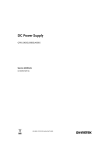
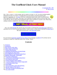
TG501
Function Generator
Service Manual
Book Part Number 48591-0130 - Issue 5
Table of Contents
General
1
Specification
2
Functional Description
4
Circuit Descriptions
6
Calibration
13
Parts List
17
General
Service Handling Precautions
Service work should only be carried out by skilled engineers. Please note that the tracks on the
printed circuit board are very fine and may lift if subjected to excessive heat. Use only a miniature
temperature controlled soldering iron and remove all solder with solder wick or suction before
attempting to remove a component.
Dismantling the Instrument
WARNING!
Opening the instrument is likely to expose live parts. The instrument shall be disconnected from all
voltage sources before any adjustment, replacement or maintenance and repair during which it shall
be opened. If afterwards any adjustment, maintenance or repair of the opened instrument under
voltage is inevitable, it shall be carried out only by a skilled person who is aware of the hazards
involved.
1.
Remove the 8 side screws and lift off the case upper and lower.
2.
Access to all components is now possible, further dismantling is not necessary.
3.
All small knobs are push on types. To remove the dial, remove the cap in the centre of the
knob using a knife blade, then loosen the nut about 1 turn. The knob and dial can then be
pulled off.
4.
Transistors Q32, Q34 and Q39 and IC22 are insulated from the rear panel.
5.
Reassemble in reverse order.
Operating Voltage
See the Power Supply section for details of changing the operating voltage from 220/240 to 110/120
and vice-versa.
1
Specification
(All specifications apply after warm-up in an ambient temperature range 18oC-28oC.)
OPERATING RANGE
Frequency Range:
.005Hz to 5MHz in 7 overlapping decade ranges with fine
adjustmentby calibrated vernier.
Internal Mode
Vernier Range:
1000:1 within each range.
Vernier Accuracy:
Better than ±5% of full scale.
External (Sweep) Mode:
Sweep Range:
1000:1 within each range.
FUNCTIONS
(Specifications apply for vernier between 0.5 and 5.0 and output 10V peak-to-peak into 50Ohm
termination).
Sine
Distortion:
Less than 0.5% to 50kHz, less than 1% to 500kHz; all harmonics
>30dB below fundamental on 1M range.
Amplitude Flatness:
± 0.2dB to 500kHz; ±1dB to 5MHz.
Triangle
Linearity:
Better than 99% to 500kHz.
Squarewave
Rise and Fall Times:
<45ns.
Mark: Space Ratio:
1:1 ±1% to 100kHz; ± 5% to 5MHz
Range:
±10V from 50 Ohm.
DC
OPERATING MODES
Run
Generator runs continuously at the selected frequency.
Triggered
Generator is quiescent until triggered by an external input at TRIG IN or by pressing MANUAL. One
complete cycle is then generated at the selected frequency, starting and stopping at the phase set
by the START/STOP PHASE control.
Gated
Generator is quiescent until gated by an external signal at TRIG IN or by pressing MANUAL.
Generator then runs continuously at the selected frequency for duration of gate signal, starting and
stopping at the phase set by the START/STOP PHASE control. Last waveform started is
completed.
Manual
Manually operates generator as described in Triggered and Gated sections.
Start/Stop Phase
The START/STOP PHASE control varies the triggered and gated signal start/ stop point from
approximately -90o to +90o up to 500kHz.
2
Symmetry
When SYM is selected the SYMMETRY control varies the duty cycle from 1:19 to 19:1 to produce
sawtooth and variable pulse-width waveforms. The indicated frequency is divided by 10 with SYM
selected.
INPUTS
Sweep Input
Input Impedance:
10kOhm
Input Sensitivity:
0 to 4V for 1000:1 sweep
Maximum Allowable Input
Voltage:
±10V
Sweep Linearity:
Better than 1%
Maximum Slew Rate of
Input Voltage:
0.1V/us
Trigger Input:
Frequency Range:
DC - 5MHz.
Signal Range:
TTL compatible levels; maximum input 20V.
Minimum Pulse Width:
50ns.
Input Impedance:
Typically 2kOhm.
OUTPUTS
50 Ohm
Amplitude Control:
>20dB vernier control within each attenuator range. Maximum output
20V peak-to-peak from 50Ohm (10V into 50Ohm).
Attenuator:
Additional switch-selectable attenu- ation of 0, -20 or -40dB. Minimum
output <20mV peak-to-peak from 50Ohm (<10mV into 50Ohm).
DC Offset Control Range:
±10V from 50Ohm. DC offset plus signal peak limited to ±10V (±5V
into 50Ohm). DC offset plus waveform attenuated proportionally in 20dB and -40dB positions.
TTL
Amplitude:
Fixed TTL level output at frequency and symmetry of main output.
Capable of driving 20 TTL loads.
GENERAL
Power Requirements
Input Voltage:
110/120V AC nominal 50/60Hz or 220/240V AC nominal 50/60Hz,
adjustable internally. The TG501 will operate safely and meet
specification within normal AC supply variations viz. 100-130V AC
and 200-260V AC respectively.
Power Consumption:
30VA Max.
Environmental Operating
Range:
Storage Temperature Range:
Size:
Weight:
+5oC to +40oC, 20% to 80% RH.
-40oC to +70oC.
300mm wide x 100mm high x 230mm deep
3.4kg
3
Functional Description
The relationships between the major circuit elements are shown in the block diagram opposite.
The summing amplifier sums the voltages from the dial and from the sweep input, and its output
controls the magnitude of the complementary current source and current sink. This current varies
from approximately 5.2uA to 5.2mA for a 1000:1 frequency change (.005-5.0).
The symmetry control adjusts the ratio between current source and current sink.
The diode gate steers current into or out of the range multiplier capacitor and is controlled by the
comparator output. When the comparator output is high the charge on the capacitor will rise,
linearly, producing the positive going triangle slope. When the comparator output is low the charge
on the capacitor will fall linearly producing the negative going triangle slope. The triangle amplifier
has unity gain and buffers the triangle wave on the multiplier capacitor to drive the comparator and
output circuits.
The comparator operates as a window detector with fixed limit points set to the triangle peaks. One
of its two outputs drives the TTL circuit and is also level shifted to drive the diode gate. The other
output drives the squarewave shaper. When the comparator output to the diode gate is high, the
triangle wave is positive going until this reaches approximately +1.2V, the comparator output then
switches low. When the comparator output is low the triangle wave is negative going until this
reaches approximately -1.2V, when the comparator output goes high, and the cycle is repeated.
4
This is the basic function generator loop in the Run mode and is shown by the double arrows in the
block diagram. Triangle and squarewave are generated simultaneously as shown.
The control logic determines Trig, Gate or Run modes. In Trig or Gate modes the waveform is
clamped by the -2I+ current sources and the diode gate, at a point determined by the Start/Stop
Phase control. A signal applied to Trig In releases the clamp and a single cycle is produced in the
Trig mode or a burst in the Gate mode, the waveform is then clamped again.
To achieve the 1, 10 and 100 ranges the 1k range capacitor is multiplied by 1000, 100 or 10 by the
capacitor multiplier circuit.
The TTL circuit buffers one of the comparator outputs to drive the TTL output socket.
The squarewave shaper converts the comparator output to a current signal and applies it to the
squarewave function switch. The sinewave converter uses the non-linear characteristics of a
transistor pair to convert the triangle wave into a sinewave, which is applied to the sinewave
function switch. The selected function is sent to the pre-amplifier where it is inverted and buffered
and applied to the output amplitude control. The signal is summed with the voltage from the DC
offset control at the output amplifier. This amplifier inverts and amplifies the signal up to 20V peak
to peak to drive the 50 Ohm output socket.
The power supply converts the incoming AC line voltage to the DC rails required by the instrument.
5
Circuit Descriptions
Power Supply - Mains connections
The operating voltage of the instrument is shown on the rear panel label. Should be it necessary to
change the operating range from 220/240V AC to 110/120V or vice-versa, change the transformer
connections following the appropriate diagram below.
If a change is made, the operating voltage label and fuse should also be changed.
For 220/240V operation use 200mA 250V time-lag
For 110/120V operation use 400mA 250V time-lag
WARNING! THIS INSTRUMENT MUST BE EARTHED
Any interruption of the protective conductor inside or outside the instrument or disconnection of the
protective earth terminal is likely to make the instrument dangerous. Intentional interruption is
prohibited.
6
Power Supply - DC Regulation
Diodes D22 to D25 rectify the transformer output and C50 and C51 are the reservoir capacitors of
the unregulated DC rails.
Q34, Q35, Q36 and IC21a form the +15V regulator, Q34 and Q35 form the compound series pass
element and Q36 its driver. IC21a is the error amplifier and a temperature compensated zener D21
provides the reference (6V2). The +15V output is set by VR34.
The -15V regulator is made up of Q37, Q38, Q39 and IC21b and complements the +15V regulator.
The -15V tracks the +15V by sensing the voltage at the junction of R149, R150 at the input of
IC21b.
The +10V rail is derived by dividing down the +15V rail; R151 and R152 provide the reference from
the +15V for the regulator IC21c and Q40.
The -10V regulator is formed by Q41 and IC21d and is the complement of the +10V regulator. The 10V tracks the +10V by sensing the voltage at the junction of R154,R155 at the input of IC21d.
The +5V rail uses a standard 3 terminal regulator IC22.
The -5V rail is divided down from the -15V by R139, R140 and buffered by a darlington emitter
follower Q32 and Q33.
Waveform Generation - Summing Amplifier and Current Sources
The dial and sweep voltages are summed by IC1, the gain of which is set by VR3. VR3 is, in fact,
used to calibrate the high end of the dial. The output range of the amplifier is approximately -4mV
(with the dial at .005) to -4V (with the dial at 5.0). This voltage is used to drive the complementary
current source and current sink as follows.
The emitter of Q1 is held at pseudo ground by IC2. If the dial is at 5.0, the -4V at the output of IC1
is forced at the emitter of Q2 by IC4. This -4V is also halved by R6, R7 and IC3 forces this voltage
(-2V) at the junction of R9, R10. A voltage dependant current is therefore set up through R8, R9,
R10 and R11.
IC5 is a current source controlled by the voltage on the collector of Q1 and IC6 is a current sink
controlled by the voltage on the collector of Q2. These two currents are steered into and out of the
range capacitor by the diode gate IC10, under the control of the comparator output.
7
When the symmetry button is depressed the short across VR8 is removed and the total resistance
between Q1 and Q2 emitters is increased from R to 10R. This lowers the current through this
resistor chain by a factor of 10 and so the frequency is divided by 10. Rotating VR8 imbalances the
current through Q1 and Q2 to give a duty cycle of up to 1:19 or 19:1.
With the symmetry button out, the waveform symmetry is set by VR9 at the top of dial (5.0). At the
bottom of the dail, symmetry is determined by offsets on ICs 1-6 (refer to calibration procedure).
Current source IC8 tracks the I+ current source IC5 and IC9 mirrors this to become -2I+. The -2I+
current is used to clamp the waveform in the Trig and Gate modes. The ramp can only stop in the
upward direction. When the Q output
of IC14b is set low, D1 is off. If the voltage at Q5 emitter is 0V (= to 0o), the voltage on the range
capacitor will ramp up and stop at 0V. When clamped the I+ current from the diode bridge flows
through the diode between pins 4 and 3 into the -2I+ current sink. A current equivalent to I+ also
flows through the diode between pins 9 and 1 into the -2I+ current sink to total 2I+. IC7 and Q5
buffer the voltage on the Start/Stop Phase control VR11 to give a low impedance voltage source on
pin 9 of IC10. This voltage can be varied between approximately +/-1.2V by VR11 corresponding to
the triangle peaks, giving +/-90o of phase control. To release the clamp the Q output of IC14b is set
high which pulls the -2I+ current sink high via D1, reverse biasing the two clamp diodes.
Waveform Generation - range selection and triangle amplifier
Range selection is by seven push-button switches, which steer the current sources into the
appropriate multiplier capacitor. The lower four ranges use the same range capacitor C9; the lower
three ranges use a capacitance multiplier. The capacitance multiplier steals current from the range
capacitor via R36. The amount of current taken is determined by the gain setting resistors R28,
R30 or R31 for the x100, x10 and x1 ranges respectively. The triangle wave on C9 is connected to
the non-inverting inputs of IC11 and IC12. The triangle wave is amplified by IC11 which has a gain
of 3; this is trimmed by VR15 to set the overall gain of the capacitance multiplier. Q8 and Q9 buffer
the output of IC12.
The triangle buffer consists of a FET source follower Q10 with temperature compensation provided
by current source Q11, which is IDSS matched with Q10. Q13 and Q14 are emitter followers to
provide 2 low impedance outputs. Q12 is strapped as a diode and compensates for the VBEs of
Q13 and Q14. VR17 trims the DC offset in this stage.
8
Waveform Generation - Comparator and TTL output
IC13 operates as a window detector and determines the peak to peak amplitude of the triangle
wave on the range multiplier capacitor, which is approximately +/-1.2V. C17-C22 compensate for
comparator and loop delays ensuring that the triangle wave amplitude remains constant with
increase in frequency. The two internal NAND gates in IC13 are wired as a flip-flop to ensure
positive switching of the comparator. C23 provides a small amount of positive feedback to ensure
jitter free operation. Some comparators oscillate with the dial at 0.005; this can be prevented by
fitting C66.
One of the comparator outputs is routed via IC17a to parallel gates IC17 c and d which drive the
TTL output. Q15 level shifts IC13 output to be about ground to drive the diode gates. Q16 is a VBE
multiplier and its total voltage is just under two VBEs. R45, R46 and C16 improve triangle linearity
at 5MHz.
IC15a and level shifter Q17 are used to drive the squarewave shaper circuit. When the squarewave
button is out, pin 4 of IC15a is held low and so the squarewave is gated off at the source.
9
Waveform Generation - Trigger Circuit
In the Trig or Gate modes the waveform is clamped at the Start/Stop Phase point under control of
IC14b (described earlier).
Q19 and IC15b form a Schmitt trigger which ensures correct operation from DC to 5MHz. R71 and
R72 with C27 fix the input threshold at <1.5V over the whole frequency range.
In the trigger mode the output of IC15b is routed through IC15c and IC16a to the monostable
formed by IC16b and c. For every high going transition at the trigger input or depression of the
manual button a 50 nanosecond pulse at IC16c output is generated. This pulse goes from high to
low, and back to high after 50ns and is used to set the flip flop IC14b which releases the waveform
clamp. The flip flop now waits for a rising edge on its clock input; this occurs when the triangle wave
changes from a negative slope to a positive slope. This edge resets the flip flop and enables the
waveform clamp circuit which stops the waveform at a point determined by the Start/Stop Phase
control.
In the gate mode the monostable around IC16b and c is disabled and the signal bypasses IC16b.
When a high level signal is applied to Trig in, the output of IC16c goes low and releases the
waveform clamp. The generator now free runs until the Trig in signal goes low and IC16c output
goes high. IC14b flip flop now waits for a rising edge on its clock input as in trigger mode and stops.
In the run mode IC14b flip flop is permanently set by SW9b, disabling the waveform clamp so that
the generator free runs.
10
Waveform Generation - Waveform Shaping
The squarewave shaper is a diode bridge which steers current from either R89 or R90 into R91.
This provides a squarewave with controlled rise/fall times, and thus no overshoot and ringing, which
is symmetrical about ground. The drive signal comes from Q17.
The sine shaper comprises a monolithic transistor array IC18 which is driven by the triangle
amplifier. The circuit has two non linear stages. A pair of emitter followers round the peaks of the
triangle which are adjusted by VR18 for the bottom of the waveform and VR22 for the top of the
waveform. The output from this stage is impressed across R78 and R81 in series and applied to the
second stage. This comprises a long tailed pair driven almost into cut off and converts the clipped
triangle wave into a sinewave. VR19 adjusts the gain of the long tailed pair to bring them close to
cut off and therefore minimum sinewave distortion. VR23 adjusts the dc operating point of the
sinewave convertor to give symmetrical operation on both positive and negative halves of the
waveform. VR20 adjusts the dc output of the convertor and VR21 output amplitude.
Output Preamplifier
The selected waveform passes to the preamplifier. Q20 and Q21 form a long- tailed pair and are in
thermal contact with each other to reduce dc drift. Q22 and Q23 are two cascaded emitter
followers; feedback is via R98. The preamplifier is an inverting virtual earth type. DC offset is
trimmed by VR26. Sine, square and triangle waveform amplitudes are set for 10V peak to peak into
50 Ohm at the 50 Ohm output by VR21, VR24 and VR25 respectively.
11
Output Amplifier and DC Offset
The signal passes via the Amplitude control VR27 to the output amplifier. A simplified diagram is
shown in fig. 7 and the following circuit description refers to this.
The HF amplifier is made up of discrete components and is in principle an inverting operational
amplifier with a gain of -10 set by R109 and R115. This has offset voltages and currents which are
compensated for by IC19 and IC20. IC19 compensates for input bias currents. IC20 controls dc
offset and LF gain by driving the non-inverting input.
Refer now to fig. 8 for the description of the HF amplifier (simplified). Q24 and Q26 are
complementary emitter followers to provide low drive impedance to the complementary class A
amplifier stage Q28 and Q29. Level shifting is achieved by adjustable zener diodes, these are
formed by a zener diode and a VBE multiplier. Note incorrect setting of the level shifters will cause
excessive current to flow in the class A stage causing damage to these devices. Refer to the
calibration section for adjustment procedure. The output of the amplifier stage is buffered by
complementary emitter followers Q30 and Q31 to drive the 50 Ohm output, D17 and D18 provide
their bias.
The non-inverting input is effectively the emitters of the class A amplifier, D19 and D20 provide the
necessary level shifting.
12
Calibration
Equipment Required
Oscilloscope
Distortion meter
4.5 digit battery powered multimeter
Calibration should be carried out after the instrument has been on for 1 hour.
Note: If any work has been done to the output stage, VR32 and VR33 must be turned fully anticlockwise before switching on.
The available calibration points are:
Dial calibration, high frequency (5.0) end, 10k range - VR3
Dial calibration, low frequency end (.005) - VR2
Waveform symmetry, high frequency end of dial (5.0) - VR9
Waveform symmetry at the low frequency end of dial (.005) is affected by offset nulling of ICs 2 to 6,
see below.
Dial calibration 1M range - VC1
Dial calibration 100k range - VC2
Capacitance multiplier offset - VR16
Capacitance multiplier gain - VR15
DC offset of triangle amplifier - VR17
Sinewave distortion - VR18, VR19, VR22 and VR23
Sinewave dc offset - VR20
13
Sinewave amplitude - VR21
Squarewave amplitude - VR24
Triangle wave amplitude - VR25
DC offset of preamplifier - VR26
Output amplifier quiescent operating current - VR32 and VR33
Output amplifier dc offset - VR31
Output amplifier bias compensation - VR28
Output amplifier LF gain - VR30
+15Vrail - VR34
For best results the above adjustments should be carried out in the following manner:
After the instrument has warmed up the case upper is removed to make any adjustments, which
should be done in a draft free environment.
Adjust VR34 for +15.0V +/-100mV at TP12
Check -15V rail is within +/-2% of the +15V rail at TP18
Check +10V rail is +10.2 +/-400mV at TP19
Check -10V rail is within +/-2% of the +10V rail at TP21
Check +5V rail is 5.0V +/-0.25V
Check -5V rail is -5.0V +/-0.25V
Select: Run, 1k range, dial at 5.0, dc offset out, squarewave, 0dB
Offset nulling of ICs 1 to 6 is critical for correct operation of the instrument. Gold plated test pins are
provided and a gold plated 2 way header on the end of the leads to the DVM is recommended to
make a good connection and help to avoid thermal e.m.f.s.
IC
TP
Adjust
DVM Reading
1
13
VR4
<40uV
2
1
VR5
<40uV
3
2
VR6
<40uV
4
3
VR7
<40uV
5
4
VR10
<40uV
6
5
VR12
<40uV
8
6
VR13
<100uV
9
7
VR14
<100uV
12
10
VR16
<100uV
Nulling of the triangle amplifier is achieved by shorting its input (TP11) and adjusting VR17 to give
<2mV at TP9.
To null the pre-amplifier, deselect the waveform output by releasing the 3 function buttons. Connect
a DVM to the right hand leg of the amplitude control (VR27) and adjust VR26 for <3mV.
Output stage adjustment must be carried out with great care to avoid circuit damage. Adjustment is
easiest with 2 voltmeters, one connected to TP15 and the other to TP14. With only one meter
available, alternately monitor the 2 test points. With no output waveform selected and the amplitude
control at minimum, slowly adjust VR32 and VR33 for 13.4V to 13.5V at the two test points. Note
14
that the voltage on these test points (TP14 and TP15) must not go below 13.3V otherwise Q28 and
Q29 will be damaged. VR32 and VR33 are interactive. Connect a DVM to TP16 and check that the
voltage on this point is <+/-1V. If not, slightly adjust VR32 or VR33 ensuring that the voltages on
TP14 and TP15 remain within 13.4V to 13.5V. Note that it may be necessary to add a low value
resistor in the meter lead close to TP14 and TP15 to prevent instability in the amplifier. Connect a
voltmeter to TP8 and adjust VR28 for <1mV. Connect a DVM to TP17 and adjust VR31 for <3mV.
Frequency multiplier to 100 range, squarewave, adjust VR30 for a flat top squarewave. Note that
the oscilloscope must be dc coupled for this adjustment.
Symmetry, select 1k range and adjust VR9 for equal mark: space ratio using the oscilloscope x10 Xmultiplier to increase resolution and the trigger slope switch.
Before commencing the vernier calibration procedure, turn the dial fully clockwise and check that
the 005 mark aligns with the mark on the front panel. If not, remove the cap in the centre of the
knob, using a knife blade and loosen the nut one to two turns. The knob can now be slid around on
its shaft to align the marks. Tighten the nut and check that the dial rotates freely against the front
panel. Refit the knob cap. On later instruments a PTFE thrust washer is fitted between the dial and
the front panel.
Dial
Multiplier
Adjust
Reading
5.0
10k
VR3
49.5 to 50.5 kHz
5.0
1M
VC1
4.9 to 5.1 MHz
5.0
100k
VC2
490 to 510 kHz
5.0
100
VR15
495 to 505 Hz
0.005
100k
VR2
465 to 475 Hz
Sinewave distortion, select sinewave, 1k range, dial at 5.0. Display the distortion meter output on
CH2 of the oscilloscope. Position VR18 and VR22 fully clockwise. Adjust VR19 to give a flat
response between peaks and VR23 to give a symmetrical display. Note, this is not minimum on the
distortion meter, do not adjust these two presets to give minimum distortion at this stage.
15
Now slowly adjust VR18 and VR22 to remove these peaks. Check the distortion meter reading
which should now be less than 0.5%, typically 0.3%. If not, very slightly adjust the above 4 presets
to achieve this. (If the instrument fails to meet specification, check the following: amplitude, linearity
and symmetry of triangle wave at TP9; pre and output amplifiers.) Adjust VR20 to trim dc output of
the sinewave converter, measured on the oscilloscope or use a DVM connected to the 50 Ohm
output (TP17). Adjust VR21 to give 10.2V peak to peak into 50 Ohm.
Triangle amplitude, adjust VR25 to give 10.2V peak to peak into 50 Ohm.
Squarewave amplitude, ajust VR24 to give 10.2V peak to peak into 50 Ohm.
Servicing Notes
The white printing on the pcb also shows all the points which are top soldered. The circles
(teardrops) show track pins and the squares show which lead of a component is top soldered.
Insulating washers are fitted to IC22, Q32, Q34 and Q39. Heatsink compound is applied to
regulators IC22, Q32, Q34 and Q39 and between transistor pair Q20 and Q21.
To help with trouble shooting the power supply etc., an external current limited (500mA) power
supply of +/-17V can be used with its ground (0V) going to the TG501 ground (negative end of C50
or positive end of C51). The +17V supply is connected to the positive end of C50 and the -17V
supply is connected to the negative end of C51.
Typical current drain from the +/-17V supply with output at minimum is -200mA and +240mA.
Input power with 240V input, 90mA maximum.
This service manual specifically covers issue 5 pcbs. Pre issue 5 boards have the following
differences:
R35 100R was fitted in series with R36//C11 and not in the sinewave converter.
R142 was 4K7
pcb support brackets were not fitted.
16
Parts List
PCB Assembly - Main
Ref
Description
Part No
R1
10RJ W25 CF
23185-0100
R2
150KJ W25 CF
23185-4150
R3
43KJ W25 CF
23187-3430
R4
10KJ W25 CF
23185-3100
R5
39KJ W25 CF
23185-3390
R6
2K7F W25 MF
23202-2270
R7
2K7F W25 MF
23202-2270
R8
2K43F W25 MF
23202-2243
R9
1K37F W25 MF
23202-2137
R10
1K37F W25 MF
23202-2137
R11
2K32F W25 MF
23202-2232
R12
750RF W25 MF
23202-1750
R13
4K3J W25 CF
23187-2430
R14
4K3J W25 CF
23187-2430
R15
750RF W25 MF
23202-1750
R16
3K3J W25 CF
23185-2330
R17
47RJ W25 CF
23185-0470
R18
47RJ W25 CF
23185-0470
R19
2K7F W25 MF
23202-2270
R20
2K7F W25 MF
23202-2270
R21
47RJ W25 CF
23185-0470
R22
47RJ W25 CF
23185-0470
R23
374RF W25 MF
23202-1374
R24
1K5J W25 CF
23185-2150
R25
1K0J W25 CF
23185-2100
R26
100RJ W25 CF
23185-1100
R27
10RJ W25 CF
23185-0100
R28
10KF W25 MF
23202-3100
R29
22KJ W25 CF
23185-3220
R30
100KF W25 MF
23202-4100
R31
1M0F W25 MF
23202-5100
R32
10KJ W25 CF
23185-3100
R33
10RJ W25 CF
23185-0100
17
18
Ref
Description
Part No
R34
10RJ W25 CF
23185-0100
R35*
100RJ W25 CF
23185-1100
R36
1K0J W25 CF
23185-2100
R37
10KJ W25 CF
23185-3100
R38
470RJ W25 CF
23185-1470
R39
220RJ W25 CF
23185-1220
R40
1K5J W25 CF
23185-2150
R41
1K5J W25 CF
23185-2150
R42
820RJ W25 CF
23185-1820
R43
1K0J W25 CF
23185-2100
R44
1K2J W25 CF
23185-2120
R45
100RJ W25 CF
23185-1100
R46
330RJ W25 CF
23185-1330
R47
14K3F W25 MF
23202-3143
R48
220RF W25 CF
23185-1220
R49
681RF W25 MF
23202-1681
R50
124RF W25 MF
23202-1124
R51
124RF W25 MF
23202-1124
R52
681RF W25 MF
23202-1681
R53
220RF W25 MF
23202-1220
R54
14K3F W25 MF
23202-3143
R55
150RJ W25 CF
23185-1150
R56
1K0J W25 CF
23185-2100
R57
1K8J W25 CF
23185-2180
R58
3K0J W25 CF
23187-2300
R59
4K7J W25 CF
23185-2470
R60
1K8J W25 CF
23185-2180
R61
3K0J W25 CF
23187-2300
R62
2K2J W25 CF
23185-2220
R63
2K2J W25 CF
23185-2220
R64
1K2J W25 CF
23185-2120
R65
4K7J W25 CF
23185-2470
R66
4K7J W25 CF
23185-2470
R67
4K7J W25 CF
23185-2470
R68
4K7J W25 CF
23185-2470
Ref
Description
Part No
R69
4K7J W25 CF
23185-2470
R70
4K7J W25 CF
23185-2470
R71
2K2J W25 CF
23185-2220
R72
1K5J W25 CF
23185-2150
R73
33KJ W25 CF
23185-3330
R74
2K2J W25 CF
23185-2220
R75
100RJ W25 CF
23185-1100
R76
47RJ W25 CF
23185-0470
R77
7K5J W25 CF
23187-2750
R78
560RJ W25 CF
23185-1560
R79
100RJ W25 CF
23185-1100
R80
7K5J W25 CF
23187-2750
R81
91RJ W25 CF
23187-0910
R82
7K5J W25 CF
23187-2750
R83
7K5J W25 CF
23187-2750
R84
68RJ W25 CF
23185-0680
R85
7K5J W25 CF
23187-2750
R86
100RJ W25 CF
23185-1100
R87
47RJ W25 CF
23185-0470
R88
10KJ W25 CF
23185-3100
R89
5K6F W25 MF
23202-2560
R90
5K6F W25 MF
23202-2560
R91
220RJ W25 CF
23185-1220
R92
470RJ W25 CF
23185-1470
R93
1K8J W25 CF
23185-2180
R94
270KJ W25 CF
23185-4270
R95
150RJ W25 CF
23185-1150
R96
6K2J W25 CF
23187-2620
R97
6K2J W25 CF
23185-2620
R98
2K2J W25 CF
23185-2220
R99
3K6J W25 CF
23187-2360
R100
3K3J W25 CF
23185-2330
R101
680RJ W50 CF
23179-1680
R102
10RJ W25 CF
23185-0100
R103
22RJ W25 CF
23185-0220
19
20
Ref
Description
Part No
R104
130KJ W25 CF
23187-4130
R105
82KJ W25 CF
23185-3820
R106
47KJ W25 CF
23185-3470
R107
22KJ W25 CF
23185-3220
R108
47KJ W25 CF
23185-3470
R109
470RJ W25 CF
23185-1470
R110
10KJ W25 CF
23185-3100
R111
560RJ W25 CF
23185-1560
R112
470RJ W25 CF
23185-1470
R113
560RJ W25 CF
23185-1560
R114
470RJ W25 CF
23185-1470
R115
4K7J W25 CF
23185-2470
R116
47RJ W25 CF
23185-0470
R117
47RJ W25 CF
23185-0470
R118
3K3J W25 CF
23185-2330
R119
10RJ W25 CF
23185-0100
R120
47RJ W25 CF
23185-0470
R121
47RJ W25 CF
23185-0470
R122
3K3J W25 CF
23185-2330
R123
10RJ W25 CF
23185-0100
R124
10RJ W25 CF
23185-0100
R125
10RJ W25 CF
23185-0100
R126
100RJ 1W CF
23183-1100
R127
100RJ 1W CF
23183-1100
R128
61R9F W25 MF
23202-0619
R129
249RF W25 MF
23202-1249
R130
61R9F W25 MF
23202-0619
R131
61R9F W25 MF
23202-0619
R132
249RF W25 MF
23202-0619
R133
121RF W25 MF
23202-1121
R134
124RF W25 MF
23202-1124
R135
3K3J W25 CF
23185-2330
R136
220RJ W25 CF
23185-1220
R137
1K0J W25 CF
23185-2100
R138
1K0J W25 CF
23185-2100
R139
3K3J W25 CF
23185-2330
R140
4K7J W25 CF
23185-2470
R141
1K0J W25 CF
23185-2100
Ref
Description
Part No
R142*
3K3J W25 CF
23185-2330
R143
220RJ W25 CF
23185-1220
R144
1K0J W25 CF
23185-2100
R145
4K7J W25 CF
23185-2470
R146
1K2J W25 CF
23185-2120
R147
8K2J W25 CF
23187-2820
R148
5K6F W25 MF
23202-2560
R149
10KF W25 MF
23202-3100
R150
10KF W25 MF
23202-3100
R151
4K7J W25 CF
23185-2470
R152
10KJ W25 CF
23185-3100
R153
4K7J W25 CF
23185-2470
R154
10KF W25 MF
23202-3100
R155
10KF W25 MF
23202-3100
R156
22KJ W25 CF
23185-3220
R157
8K2J W25 CF
23185-2820
R158
3K9J W25 CF
23185-2390
R159
1K8J W25 CF
23185-2180
R160
2K2J W25 CF
23185-2220
R161
ZERO OHM
23185-0000
R162
ZERO OHM
23185-0000
R163
ZERO OHM
23185-0000
R164
ZERO OHM
23185-0000
R165
ZERO OHM
23185-0000
R166
ZERO OHM
23185-0000
R167
22KJ W25 CF
23185-3220
R168
22KJ W25 CF
23185-3220
R169
100RJ W25 CF
23185-2100
R170
6K8J W25 CF
23185-2680
R171
10RJ W25 CF
23185-0100
*R35 was fitted in series with R36//C11 on pre issue 5 pcbs
21
Ref
Description
Part No
VR2
Preset 22K
23377-3220
VR3
Preset 10K
23377-3100
VR4
Preset 10K
23377-3100
VR5
Preset 10K
23377-3100
VR6
Preset 10K
23377-3100
VR7
Preset 10K
23377-3100
VR9
Preset 220R
23377-1220
VR10
Preset 10K
23377-3100
VR12
Preset 10K
23377-3100
VR13
Preset 10K
23377-3100
VR14
Preset 10K
23377-3100
VR15
Preset 1K0
23377-2100
VR16
Preset 10K
23377-3100
VR17
Preset 470R
23377-1470
VR18
Preset 4K7
23377-2470
VR19
Preset 100R
23377-1100
VR20
Preset 2K2
23377-2220
VR21
Preset 100R
23377-1100
VR22
Preset 4K7
23377-2470
VR23
Preset 10K
23377-3100
VR24
Preset 1K0
23377-2100
VR25
Preset 1K0
23377-2100
VR26
Preset 22K
23377-3220
VR27
Pot 470R Lin
23347-0110
VR28
Preset 10K
23377-3100
VR30
Preset 22K
23377-3220
VR31
Preset 10K
23377-3100
VR32
Preset 2K2
23377-2220
VR33
Preset 2K2
23377-2220
VR34
Preset 2K2
23377-2220
*R142 was 4K7 on pre-issue 5 pcbs
22
Ref
Description
Part No
C1
10NZ 63V Cer
23427-0325
C2
10NZ 63V Cer
23427-0325
C3
10NZ 63V Cer
23427-0325
C4
10NZ 63V Cer
23427-0325
C5
150PF 630V P/S
23647-0515
C6
1N8F 160V P/S
23646-0009
C7
82PK 30V P/S
23646-0708
C8
22NG 100V P/E
23620-0805
C9
220NG 100V P/E
23620-0804
C10
100NJ 100V P/E
23620-0207
C11
4N7K 63V Cer
23427-0346
C12
10NZ 63V Cer
23427-0325
C13
10NZ 63V Cer
23427-0325
C14
10NZ 63V Cer
23427-0325
C15
10NZ 63V Cer
23427-0325
C16
47PG 63V Cer
23427-0329
C17
18PG 63V Cer
23427-0337
C18
22PG 63V Cer
23427-0323
C19
82PG 63V Cer
23427-0349
C20
82PG 63V Cer
23427-0349
C21
3N3F 160V P/S
23646-0007
C22
3N3F 160V P/S
23646-0007
C23
10PC 63V Cer
23427-0328
C24
10NZ 63V Cer
23427-0325
C25
10NZ 63V Cer
23427-0325
C26
10NZ 63V Cer
23427-0325
C27
22PG 63V Cer
23427-0323
C28
270PG 63V Cer
23427-0347
C29
10NZ 63V Cer
23427-0325
C30
68PG 63V Cer
23427-0332
C31
100NS 63V Cer
23438-0007
C32
2P2C 50V Cer
23427-0524
C33
10NZ 63V Cer
23427-0325
C34
10NZ 63V Cer
23427-0325
C35
100NS 63V Cer
23438-0007
23
24
Ref
Description
Part No
C36
100NS 63V Cer
23438-0007
C37
Not used
C38
100NJ 100V P/E
23620-0207
C39
1N0K 63V Cer
23427-0331
C40
0.47UF 35V Tant
23594-0231
C41
10UF 16V Tant
23594-0219
C42
10UF 16V Tant
23594-0219
C43
0.47UF 35V Tant
23594-0231
C44
100NS 63V Cer
23438-0007
C45
100NS 63V Cer
23438-0007
C46
10UF 16V Tant
23594-0219
C47
10UF 16V Tant
23594-0219
C48
100NS 63V Cer
23438-0007
C49
100NS 63V Cer
23438-0007
C50
1000UF 63V Elec
23557-0244
C51
1000UF 63V Elec
23557-0244
C52
100NS 63V Cer
23438-0007
C53
100PG 63V Cer
23427-0322
C54
100PG 63V Cer
23427-0322
C55
100UF 25V Elec
23557-0650
C56
10NZ 63V Cer
23427-0325
C57
100UF 25V Elec
23557-0650
C58
10NZ 63V Cer
23427-0325
C59
100UF 25V Elec
23557-0650
C60
100UF 25V Elec
23557-0650
C61
1P8C 63V Cer
23427-0310
C62
10NZ 63V Cer
23427-0325
C63
10NZ 63V Cer
23427-0325
C64
10NZ 63V Cer
23427-0325
C65
10NZ 63V Cer
23427-0325
*C66
2P2C 50V Cer
23427-0524
C67
270PG 63V Cer
23427-0347
VC1
4-64pF Poly/P
23984-0001
VC2
4-64pF Poly/P
23984-0001
Ref
Description
Part No
D1
Dio 1N4148
25021-0901
D2
Dio 1N4148
25021-0901
D3
Dio 1N4148
25021-0901
D4
Dio 1N4148
25021-0901
D5
Dio 1N4148
25021-0901
D6
Dio 1N4148
25021-0901
D7
Dio 1N4148
25021-0901
D8
Dio 1N4148
25021-0901
D9
Dio 1N4148
25021-0901
D10
Dio 1N4148
25021-0901
D11
Dio 1N4148
25021-0901
D12
Dio 1N4148
25021-0901
D13
Dio 1N4148
25021-0901
D14
Dio BZX79C11
25130-0910
D15
Dio BZX79C11
25130-0910
D16
Dio 1N4148
25021-0901
D17
Dio 1N4148
25021-0901
D18
Dio 1N4148
25021-0901
D19
Dio BZX83C11
25130-0908
D20
Dio BZX83C11
25130-0908
D21
Dio 1N821
25130-0226
D22
Dio 1N4002
25115-0907
D23
Dio 1N4002
25115-0907
D24
Dio 1N4002
25115-0907
D25
Dio 1N4002
25115-0907
D26
Dio 1N4148
25021-0901
D27
Dio BZX83C5V6
25130-0217
D28
Dio 1N4148
25021-0901
D29
Dio 1N4148
25021-0901
D30
Dio 1N4148
25021-0901
*C66 is optional. See circuit diagram
25
26
Ref
Description
Part No
Q1
Tran ZTX239
25380-0229
Q2
Tran ZTX214
25341-0214
Q3
Tran ZTX214
25341-0214
Q4
Tran ZTX239
25380-0229
Q5
Tran ZTX239
25380-0229
Q6
Tran ZTX214
25341-0214
Q7
Tran ZTX239
25380-0229
Q8
Tran ZTX239
25380-0229
Q9
Tran ZTX214
25341-0214
*Q10
Tran BF245A
25601-0103
*Q11
Tran BF245A
25601-0103
Q12
Tran ZTX214
25341-0214
Q13
Tran ZTX214
25341-0214
Q14
Tran ZTX214
25341-0214
Q15
Tran 2N3904
25381-0404
Q16
Tran ZTX239
25380-0229
Q17
Tran 2N3904
25381-0404
Q18
Tran 2N3904
25381-0404
Q19
Tran ZTX313
25380-0230
Q20
Tran 2N3904
25381-0404
Q21
Tran 2N3904
25381-0404
Q22
Tran 2N3904
25381-0404
Q23
Tran 2N2219A
25377-0700
Q24
Tran 2N3906
25341-0218
Q25
Tran ZTX239
25380-0229
Q26
Tran 2N3904
25381-0404
Q27
Tran ZTX239
25380-0229
Q28
Tran 2N3906
25341-0218
Q29
Tran 2N3904
25381-0404
Q30
Tran 2N2219A
25377-0700
Q31
Tran 2N2905A
25344-0500
Q32
Tran BD240
25344-0020
Q33
Tran ZTX214
25341-0214
Q34
Tran BD240
25344-0020
Q35
Tran 2N3904
25381-0404
Ref
Description
Part No
Q36
Tran 2N3904
25381-0404
Q37
Tran 2N3906
25341-0218
Q38
Tran 2N3906
25341-0218
Q39
Tran BD239
25382-0500
Q40
Tran BC338
25383-0505
Q41
Tran ZTX550
25341-0215
*Q10 & Q11 are matched devices
Ref
Description
Part No
IC1
LF441CN
27106-0621
IC2
LF441CN
27106-0621
IC3
LF441CN
27106-0621
IC4
LF441CN
27106-0621
IC5
LF441CN
27106-0621
IC6
LF441CN
27106-0621
IC7
TL071CP
27106-0604
IC8
TL071CP
27106-0604
IC9
TL071CP
27106-0604
IC10
CA3019
27164-0600
IC11
TL071CP
27106-0604
IC12
TL071CP
27106-0604
IC13
NE521N
27254-0010
IC14
74LS74
27223-0740
IC15
74LS00
27223-0000
IC16
74LS00
27223-0000
IC17
7400
27220-0000
IC18
CA3127E
27164-0504
IC19
TL071CP
27106-0604
IC20
TL071CP
27106-0604
IC21
LM324N
27106-0506
IC22
LM340T-5
27160-0009
27
Description
Switchbank
12 Way
22225-0540
Switchbank
7 Way
22225-0550
Button, black
13 off
37113-0130
Button, grey
6 off
37113-0140
Stud 3mm x 10mmL (for pot bracket)
2 off
20205-0610
Track pins
16 off
22469-0502
Vero pins (LV AC from transformer, TP12,TP14 to 22 inc.)
12 off
22469-0200
Transistor pad (for Q23,30,31)
3 off
20661-0801
Heatsink,TO5 (for Q23,30,31)
3 off
20670-0040
Header, 2 Way (TP1 to TP11 inc, (TP13)
12 off
22573-0041
Zero ohm resistors (LK1 to LK69 inc., J1, J2, J3 & J4)
73 off
23185-0000
Socket IC 8 pin
13 off
22574-0118
Socket IC 14 pin
6 off
22574-0119
Socket IC 16 pin
22574-0120
Bracket, potentiometer (for VR27)
33141-0540
Spindle, extension (for VR27)
23347-0720
Washer, shakeproof, M3 (for pot bracket)
2 off
20037-0301
Wahser, M3 (for pcb bracket)
2 off
20030-0203
Nut, M3 (for pot bracket (2)), for pcb bracket (2))
4 off
20210.0101
PCB Support bracket
2 off
20663-0010
Screw M3 x 8mmL (for pcb bracket)
2 off
20234-0012
Adhesive pad (for C51,C52)
4 off
10300-0313
Terminal for T1
3 off
35311-0020
PCB, Main TG501/2/3
28
Part No.
35555-0510
Front Panel Assy TG501
Description
Part No
Front Panel TG501
*33331-0710
Dial, single scale
37571-0060
Washer PTFE for dial
31122-0220
Knob, black, for dial
20657-0020
Cap, for dial knob
20657-0021
Knob, push-on
4 off
20657-0001
Cap, for knob
4 off
20657-0009
Pot 25KJ WW (VR8)
23356-0010
Pot 10KM CP (VR1)
23348-0010
Nut (for VR1)
23348-0700
Washer (for VR1)
23348-0701
Pot 1K0M CF (VR11)
23347-0029
Pot 10KM CF (VR29)
23347-0030
Pot 4700MM (VR27)
23347-0110
BNC Socket
4 off
22588-0004
Bushing, BNC insulating
8 off
22588-0700
LED.
25061-0200
Adhesive pad for LED
10300-0313
Sleeve for LED wire
10232-0303
Solder tag, shakeproof (for earth wire)
*20037-0400
Rear Panel Assy - TG501
Description
Part No.
Rear Panel
*33331-0820
AC Mains Receptacle
22520-0120
Shroud for receptacle
22458-0004
Fuseholder
22300-0210
Shroud for fuseholder
22458-0001
Fuse 200mA slow blow (for 220/240V input)
or
22315-0227
Fuse 400mA slow blow (for 110/120V input)
22315-0236
Switch, rocker
22219-0030
Connector, shrouded push-on for switch
4 off
Transformer (T1)
22454-0030
22115-0040
Spacer M4 x 15mmL (for T1)
4 off
20661-0224
Screw M4 x 45mmL (for T1)
4 off
20234-0030
Washer shakeproof M4 (for T1)
8 off
20037-0304
Nut M4 (for T1)
5 off
20210-0102
29
Description
Part No.
Screw M3 x 10mmL
2 off
20234-0011
Washer, shakeproof M3 (for Mains skt)
2 off
20037-0301
Washer, M3 (for Mains skt)
2 off
20030-0263
Nut, M3 Mains skt
2 off
20210-0101
Screw M4 x 8mmL (for Mains earth)
20234-0023
Solder tag, shakeproof 4BA (for earth wires)
2 off
20037-0401
Washer ,insulating TO220 (for Q32, 34, 39 & IC22)
4 off
20613-0006
Screw M3 x 8mmL nylon (for Q32, 34, 39 & IC22)
4 off
20224-0200
Nut M3 nylon (for Q32,34,39 & IC22)
4 off
20210-0200
Label, On/Off
37511-0340
Label, Serial No
37558-0460
Case Parts
Description
Part No.
Case Upper
*33537-0240
Case Lower
*33537-0250
Bracket, side
2 off
*31547-0140
Screw M3 x 8mmL mushroom head (case upper/lower to side
brackets)
8 off
20237-0001
Screw M3 x 5mmL Taptite (PCB securing)
4 off
20062-0500
Washer M3 (PCB securing)
4 off
20030-0263
Screw M3 x 10mmL (Rear panel securing)
4 off
20234-0011
Washer M3, shakeproof (Front & Rear Panel securing)
12 off
20037-0301
Nut M3 (Front & Rear Panel securing)
8 off
20210-0101
Foot, swivel
20662-0200
Bracket,foot, pair
20662-0201
Foot, PVC, black
2 off
20662-0520
Screw M4 x 12mml
4 off
20234-0029
Nut M4
4 off
20210-0102
Washer M5
2 off
20030-0267
Washer, shakeproof
4 off
20037-0304
Cable tie
4 off
20653-0204
Hardware for all feet securing:
30
Spring foot (silver bar)
33171-0130
Black feet (pair)
20662-0201
Packaging Parts
Description
Part No
Carton - TG501
*38114-0100
Load spreader for carton
*38114-0105
End Cap for carton
2 off
*20664-0170
Label, wiring instructions (for tinned ends Mains lead)
37541-0490
Mains Lead tinned ends
or
22491-0010
Mains lead Euro plug
or
22491-0020
Mains lead USA plug
22491-0040
Guarantee Card
48581-0230
Instruction Book
48591-0100
Parts Changes
From September 1988 a new case with changed cosmetics was introduced. This consisted of a
different case upper and lower, front and rear panels, side support brackets and the use of case
bezels to front and rear. The front panel earth wire connection by the shakeproof solder tag was no
longer required. A new carton was also introduced to accomodate the new case. The old and new
parts, which are not interchangeable, are as follows:
Old Parts
Description
Part No
Case Upper
33537-0240
Case Lower
33537-0250
Front Panel
33331-0710
Rear Panel
33331-0820
Side Bracket
2 off
31547-0140
Solder tag, shakeproof
20037-0400
Carton
38114-0100
Load spreader for carton
38114-0105
End Cap for carton
2 off
20664-0170
New Parts
Description
Part No
Case Upper
33537-0500
Case Upper
33537-0510
Front Panel
33331-1400
Rear Panel
33331-1410
Side Bracket
2 off
31547-0290
Bezel, Case
2 off
31711-0050
Carton
38114-0150
Load spreader for carton
38114-0155
End Cap for carton
2 off
20664-0200
31