1
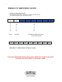
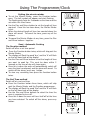
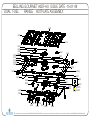
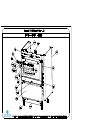
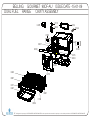
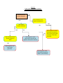
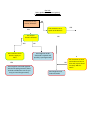
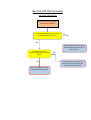
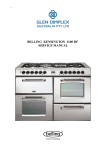
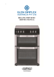
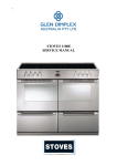
1 BELLING GOURMET 900 DF SERVICE MANUAL 2 INDEX PRODUCT IDENTIFICATION PAGE APPLIANCE RATING PLATE ............................................................. 3 USER GUIDE AND INSTALLATION HANDBOOK USER GUIDE.......................................................................................... INSTALLATION INSTRUCTIONS....................................................... TECHNICAL DATA............................................................................... CONTACT DETAILS ............................................................................ WIRING DIAGRAM............................................................................... PARTS LIST GOURMET 900 DF......................................................... REPAIR AND MAINTAINANCE 4-28 29-34 35-36 37-38 39-39 40-46 DISASSEMBLY PROCEDURES.......................................................... COMPONANT REMOVAL.................................................................. TECHNICAL SPECIFICATIONS......................................................... FAULTFINDING GUIDES................................................................... 47-53 54-61 62-62 63-76 THIS MANUAL COVERS THE FOLLOWING MODELS :BELLING GOURMET 900 DF 3 PRODUCT IDENTIFICATION Appliance rating plate location The appliance rating plate is located on the right-hand side of the front frame and also on the rear service panel 9 10 YEAR 4 1 8 MONTH 4 4 3 2 8 NUMBER OF PRODUCTION FOR THE MONTH 4 4 4 0 0 2 8 PRODUCT IDENTIFICATION CODE It is important that during all service calls the model and serial numbers are recorded on all paper work. Our Warranty Should you need it . . . . Inside the paperwork which has come with this appliance, there is a leaflet and card explaining the terms of our extended warranty and guarantee. In order to apply for our five year guarantee, simply fill in the details on the card and post it off, this will register your appliance. Should you wish to take out extended warranty, please fill in the details on the leaflet and post this off to: Glen Dimplex Australia, Unit 2, 205 Abbotts Road Dandenong South Victoria 3175 Australia If your appliance is covered by the warranty and guarantee, you will not be billed for work undertaken should your appliance be faulty, terms and conditions do apply, so please read through the literature carefully. Please ensure that you have available your appliances model number and serial number, there is a space at the back of this book for recording that information. IMPORTANT NOTICE Please note the cooling fan fitted to this appliance is an integral part of its safety and functionality. When the appliance is installed care must be taken that the cooling fans performance is not impeded by any objects coming into contact with it. (Installation pipes, leads etc) Care must also be taken that there is sufficient air flow at the rear of the appliance for the cooling fan to run at its optimum efficiency. (Particularly Built In appliances) See clearance dimensions in the installation section of the booklet. During use the Appliance must never be disconnected from the Mains supply as this will seriously affect the safety and performance of the appliance, particularly in relation to surface temperatures becoming hot and gas operated parts not working efficiently. The cooling fan is designed to run on after the control knob has been switched off to keep the front of the appliance and the controls cool until the appliance has naturally cooled itself. Contents User’s Section . . . . . . . . . . . . . . . . . . . . . . . . . . . . . . . . . . . . . . . . . . . . . . . . . . . . . . Hob and cooker safety . . . . . . . . . . . . . . . . . . . . . . . . . . . . . . . . . . . . . . . . . . . . . . . . 4 Chip pan fires . . . . . . . . . . . . . . . . . . . . . . . . . . . . . . . . . . . . . . . . . . . . . . . . . . . . . . 5 Using the programmer / clock. . . . . . . . . . . . . . . . . . . . . . . . . . . . . . . . . . . . . . . . . . . 6 Using your gas hob . . . . . . . . . . . . . . . . . . . . . . . . . . . . . . . . . . . . . . . . . . . . . . . . . Using your gas hob . . . . . . . . . . . . . . . . . . . . . . . . . . . . . . . . . . . . . . . . . . . . . . . . . . 9 Using your ovens / grill . . . . . . . . . . . . . . . . . . . . . . . . . . . . . . . . . . . . . . . . . . . . . . Using your Multifunction oven . . . . . . . . . . . . . . . . . . . . . . . . . . . . . . . . . . . . . . . . . . 10 Using your fan oven (if fitted) . . . . . . . . . . . . . . . . . . . . . . . . . . . . . . . . . . . . . . . . . . 11 Oven and grill functions . . . . . . . . . . . . . . . . . . . . . . . . . . . . . . . . . . . . . . . . . . . . . . 12 Using your Multifunction oven grill. . . . . . . . . . . . . . . . . . . . . . . . . . . . . . . . . . . . . . . 13 Cooking guides . . . . . . . . . . . . . . . . . . . . . . . . . . . . . . . . . . . . . . . . . . . . . . . . . . . . 14 Cooling and defrosting function. . . . . . . . . . . . . . . . . . . . . . . . . . . . . . . . . . . . . . . . . 19 Cleaning and maintaining your appliance . . . . . . . . . . . . . . . . . . . . . . . . . . . . . . . Cleaning your gas hob . . . . . . . . . . . . . . . . . . . . . . . . . . . . . . . . . . . . . . . . . . . . . . . 20 Cleaning your cavities. . . . . . . . . . . . . . . . . . . . . . . . . . . . . . . . . . . . . . . . . . . . . . . . 21 Telescopic shelving system . . . . . . . . . . . . . . . . . . . . . . . . . . . . . . . . . . . . . . . . . . . . 22 Cleaning your appliance . . . . . . . . . . . . . . . . . . . . . . . . . . . . . . . . . . . . . . . . . . . . . . 23 Before you call. . . . . . . . . . . . . . . . . . . . . . . . . . . . . . . . . . . . . . . . . . . . . . . . . . . . . 24 Changing light bulbs. . . . . . . . . . . . . . . . . . . . . . . . . . . . . . . . . . . . . . . . . . . . . . . . . 25 Installation Instructions . . . . . . . . . . . . . . . . . . . . . . . . . . . . . . . . . . . . . . . . . . . . 26 Technical Data . . . . . . . . . . . . . . . . . . . . . . . . . . . . . . . . . . . . . . . . . . . . . . . . . . . . 32 Customer Care . . . . . . . . . . . . . . . . . . . . . . . . . . . . . . . . . . . . . . . . . . . . . Back cover Hob & Cooker Safety Always ensure that pan bases are dry, and flat before ! using them on the hob. Always position pans over the centre of the burner, and turn the handles to a safe position so they cannot be knocked or grabbed. Always use pans which are no smaller than 100mm (4”), or larger than 250mm (10”). Always take care when removing food from the oven as the area around the cavity may be hot. Always use oven gloves when handling any utensils which have been in the oven as they will be hot. Always make sure that the oven shelves are resting in the correct position in between two runners. Do not place the oven shelves on top of the highest runner, this will lead to spillage and injury if the baking tray, or dish falls. Never use double pans, rimbased pans, old or misshapen pans, or any pan which is not stable on a flat surface. Never leave cooking fat, or oil, unattended. Never use commercial simmering aids, or heat diffusers, as they create excessive heat and can damage the surface of the hob. Never use the hob for any other purpose than cooking food. Plastic cooking utensils can melt if they come into contact with a warm hob. Never leave them close to, or on top of, the hob. Never leave the burner alight without a pan covering it. This causes a fire hazard. Do not place items of the door while it is open. Do not wrap foil around the oven shelves, or allow it to block the flue. Do not drape tea towels near the oven while it is on, this will cause a fire hazard. Do not pull heavy items, such as turkeys, or large joints of meat, out from the oven on the shelf, as they may overbalance and fall. Do not use this appliance to heat anything other than food items, and do not use it for heating the room. 4 WARNING: Parts of the appliance may become hot while in use, always make sure that children are supervised when they are near to the appliance. Always make sure that the burner caps, rings and pansupports are correctly placed. This will prevent pans becoming unstable while in use, and ensure an uninterrupted gas flow. i Call Customer Care for a service engineers visit if: You find over a period of time that the gas oven becomes hotter at a particular temperature - the thermostat may need replacing. The cooling fan fails to work. Children should be supervised to ensure that they do not play with the appliance. This appliance is not intended for use by persons (including children with reduced physical, sensory or mental capabilities, or lack of experience and knowledge), unless they have been given supervision or instruction concerning use of the appliance by a person responsible for their safety. WARNING: Servicing should be carried out only by authorised personnel. Chip Pan Fires What causes a chip pan fire? Chip pan fires start when oil of fat overheats and catches fire, or when oil or fat spills on to the cooker because the pan has been filled too high. They can also start when wet chips are put into hot oil, making it bubble up and over flow. Do not spray aerosols in the vicinity of this appliance while it is in operation. Do not store or use flammable liquids or items in the vicinity of this appliance. Preventing a chip pan fire Do not modify this appliance. Never fill the pan more than a third full with oil of fat. Never leave the pan alone with the heat on - even for a few seconds. Dry chips before putting them in the pan. Never put chips in the pan if the oil has started smoking. Turn off the heat and leave the oil to cool down, or else it could catch fire. In the event of a chip pan fire If your chip pan does catch fire - don’t panic, and don’t move the pan. Serious burns are often caused by picking up the pan and running outside with it. If it is safe to do so, and you don’t have to reach across the pan, turn off the heat. Never throw water, or use a fire extinguisher. If you can, drape a damp cloth or towel over the pan to smother the flames. Leave the pan to cool down for at least half an hour. If you can’t control the fire yourself, close the door, get out and tell everybody else to get out. Call the fire brigade. Don’t go back inside whatever the reason. 5 Using The Programmer/Clock Through your programmer you will be able to set the time of day, set the minute minder, and use the semi and fully automatic cooking functions. The programmer is vital to the working of your appliance, and reading this section will make sure that you get the most out of your ovens. What your timer symbols mean. A The programmer buttons There are three buttons on this type of timer. The table below shows you what their symbols look like, depending on the model type, and what they do. Symbol Symbol What is it? Down / Minus Used to decrease cook / end time, remove minutes from the minute minder and adjust the time of day. Also for listening to and setting the alarm tone. - Up / Plus + Used to increase cook / end time, add minutes to the minute minder and adjust the time of day. Function button Used to select the functions available on this timer. Press once for: Minute Minder. Press twice for: Cook time Press three times for: End time. How to use these functions is explained later on in this section. i This is a 24 hour clock. Before you do anything with your appliance you must set the correct time of day. Setting the time of day Press the Plus and Minus buttons together for a few seconds and release. Set the time of day using the Plus and Minus buttons. Press once for single digit increase, press and hold for rapid increase.. Once the time of day has been set wait approx 10 seconds until the ‘’ stops flashing. Use the appliance as normal. Setting an alarm tone There are three tones to choose from. Press and release the minus button. Once the minus button is released, the tone is selected. 6 A Using The Programmer/Clock Setting the minute minder To set the Minute Minder, press the Function button once. The bell symbol will appear and start flashing. The flashing only lasts for 5 seconds so the time must be set within this time frame. Use the Plus and Minus button to set the length of time required. Once this has been done, the Minute Minder is set. When the desired length of time has counted down the alarm will sound. To cancel the tone, press any of the buttons. To cancel the Minute Minder at any time, press the Plus and Minus buttons together. Semi - Automatic Cooking The Duration method Switch off after a set time period Press the Function button twice, which will skip past the Minute Minder. The display will flash the word ‘dur’, and the ‘A’ will flash on the left hand side of the display. Use the Plus and Minus buttons to set the length of time you want to cook for. This must be done within 5 seconds or the time of day will show again. Once this is done the oven will automatically switch off once the time has elapsed, and the alarm will sound. To switch off the alarm, press any button. To view any remaining time press the function button twice. The End Time method Switch off at a set end time Press the Function button three times, which will skip past the Minute Minder and the Duration programmer. The display will flash the word ‘End’ and the ‘A’ will flash on the left hand side of the display. Use the Plus and Minus buttons to select the time the oven is required to turn off. Once this is done the oven will turn itself off at the time you have selected. To switch off the alarm, press any button. A A A A A A 7 Setting the Programmer A Fully Automatic Cooking Switch on and off automatically This requires both the duration and the end time to be entered. The timer will work out the start time and begin cooking. Press the Function button twice, which will skip past the Minute Minder. The display will flash the word ‘dur’, and the ‘A’ will flash on the left hand side of the display. Use the Plus and Minus buttons to set the length of time you want to cook for. This must be done within 5 seconds or the time of day will show again. Press the Function button three times, which will skip past the Minute Minder and the Duration programmer. The display will flash the word ‘End’ and the ‘A’ will flash on the left hand side of the display. Use the Plus and Minus buttons to select the time the oven is required to turn off. Once this is done the oven will turn itself off at the time you have selected. To switch off the alarm, press any button. Set the temperature of the oven and place the food inside. The timer will calculate the appropriate start time. When using the Programmer: Do: Familiarise yourself with the use of the programmer. Select foods which are as fresh and as cold as possible preferably straight from the refrigerator. Choose foods which are suitable for cooking from a cold start, as some dishes will be affected by being left uncooked, at room temperature. Make sure that meat, poultry and uncooked food are thoroughly thawed before placing them in the oven. Cover dishes with lids or foil. Try to keep the end time as close to your return as possible. Do not: Place warm food in the oven for delayed cooking foods must be thoroughly cooled before placing in the oven, the oven must also be cool before you start. Cook dishes containing left over cooked meat or poultry, or pastry dishes with wet fillings, they are not suitable! Over-fill dishes containing liquids. A A A A A 8 i The automatic cooking symbol will appear to show that the oven is no longer in manual mode but in automatic mode. i Important: Once the oven has switched itself off please make sure you turn to oven controls to the ‘off’ position and set the oven to manual by pressing the Cook Time and Ready Time buttons together. i Important: Remove food as soon as it is cooked. Using Your Gas Hob Hob Ignition To turn on, place your pan onto the pan supports above the burner you wish to use. Push in and turn the selected control knob anticlockwise, to the full on symbol. Your hob has an ignition button on the fascia panel, press it in until your burner lights. Hold the control knob in for 15 seconds. Do not hold the control knob in for any longer than 15 seconds. If the burner fails to light within this time, release the control knob and wait one minute before attempting to re-ignite. To simmer, turn the control knob to the small flame symbol. This will ensure that the flame is just large enough to gently heat the contents of the pan. To turn off, turn the control knob clockwise to the ‘off’ position. Always make sure that your pans are place correctly on the burners as shown, and do not allow the flame to extend over the base of the pan. Energy Saving Position pans centrally over the burners. Only heat the amount of liquid you need. Once liquids have been brought to the boil, reduce the heat setting to a simmer. Consider using a pressure cooker if possible. Vegetables in small pieces will cook quicker. Use a pan which is a close match to your burner size. Smaller burners are ideal for simmering and stewing in smaller pans, while the larger burners are ideal for frying and boiling. Abnormal Operation Any of the following are considered to be abnormal operation and may require servicing. - Yellow tipping of the hob burner flame - Sooting up of the cooking utensils - Burners not igniting properly - Burners failing to remain alight - Burners extinguished by cupboard doors - Gas valves which are difficult to turn In case the appliance fails to operate correctly, contact the authorised service provider in your area. 9 i How can I tell if my hob has thermocouples? Picture A below: shows a burner without thermocouples. Picture B below: shows a burner with thermocouples. A B ! ! i In the event of a power failure, or the ignition not working: Push in and turn the control knob to start the gas, then hold a lighted match or taper to the burner until it lights. i Use flat based pans which are the correct size for your burners and suitable for your hob type. We recommend the following sizes: 100mm or 4” min. 250mm or 10” max. Smaller or larger pan sizes may lead to slower cooking times. Using Your Multifunction Oven The multifunction oven may be controlled by the programmer (see The Programmer/Clock for details). The programmer, if fitted must be set to manual before it can be used, or programmed. Switching on the multifunction oven Use the function control knob to select the function you wish to use - see the functions table for details. Note: You can change function during cooking if you wish, as long as the oven is in manual mode. Turn the temperature control knob to the temperature you wish to use. The thermostat indicator will come on to show that the oven is heating, and once the temperature is achieved, it will go out. To switch off the oven, simply turn the control knob back to the ‘ ‘ position. The cooling fan mayl come on during use, and may continue to run for some time afterwards. 10 i Important: Never place food, or dishes on the base of the main oven, the element is here and it will cause over heating. Using Your Fanned Oven (if fitted) Switching on the fanned oven Use the fanned oven control to turn your oven on, and select your temperature. The thermostat indicator will come on to show that the oven is heating, and once the temperature is achieved, it will go out. To switch off the oven, simply turn the control knob back to the ‘ ‘ position. The cooling fan may come on during use, and may continue to run for some time afterwards. 11 i Important: Never place food, or dishes on the base of the main oven, the element is here and it will cause over heating. Oven & Grill Functions Main Oven Function Recommended Uses Base Heat Only Used to finish off the bases of food following cooking using the conventional or fanned modes. The base heat can be used to provide additional browning for pizzas, pies and quiche. Use this function towards the end of cooking. Top Heat Only The heat is ideal from browning off the tops of food as it is not as fierce as the grill following conventional or fanned cooking. Provides additional browning for dishes like Lasagna or Cauliflower cheese. Use this function towards the end of cooking. Conventional Oven This function is ideal for traditional roasting. The meat is placed in the middle of the oven, roast potatoes towards the top. Intensive Bake Suitable for food with a high moisture content, such as quiche, bread and cheesecake. It also eliminates the need for baking pastry blind. Fanned Oven The even temperature in the oven makes this function suitable for batch baking, or batch cooking foods. Defrost To defrost foods, such as cream cakes/gateaux, use with the oven door closed. For cooling dishes prior to refrigeration, leave the door open. Dual Grill This function cooks food from the top and is ideal for a range of food from toast to steaks. As the whole grill is working, you can cook larger quantities of food. Base Heat with Fan Used to cook open pies (such as mince pies) the base element ensures that the base is cooked while the fan allows the air to circulate around the filling - without being too intensive. Fanned Grill The fan allows the heat to circulate around the food. Ideal for thinner foods such as bacon, fish and gammon steaks. Foods do not require turning. Use with the oven door closed. 12 Using Your Multifunction Oven Grill Before you start grilling. . . . Before you use the grill, make sure you have placed the grill shelf in the position you need as once the grill is on you may injure yourself if you try to move the shelf. This grill function can be used with the door open, or closed. Turn the selector control knob to the grill setting. Turn the grill control knob to either the dual or single grill setting. Then select the heat setting. To switch off, return the control knobs to the ‘off’ position. The cooling fan will come on during use, and may continue to run for some time afterwards. To adjust your results, you can turn the trivet over, or remove it altogether. If your grill is a dual grill: The dual grill uses all of the top element and is ideal for grilling large quantities of food. The single grill uses part of the element only, and is better suited to grill smaller amounts of food. The grill neon When grilling with the door closed, the neon will cycle on and off as the temperature is maintained inside the cavity. If the door is open, it will not cycle on and off. 13 i Warning: Accessible parts may become hot when the grill is in use. Chidren should be kept away. i Types of grill Fixed rate grill: has a full ‘on’ setting and ‘off’. Variable rate grill: has adjustable heat settings 1 (low) to 8 (high) or 5 (high) - depending on the model. Single grill: has one grill element. Dual grill: has two grill elements which can be used together, or as a single grill. i For best results: Pre-heat the grill for about 3 minutes. Fanned Oven Guide Some adjustment will have to be made to conventional cooking temperatures. The table below shows conventional cooking temperatures, fanned temperatures and gas marks. For optimum results using the fanned oven setting, conventional temperatures need to be converted to the fanned oven temperatures. For example and item which would cook at 180˚C will now cook at the fanned oven temperature of 160˚C. This is a high efficiency oven, you may notice an emission of steam when the door is opened. When cooking chilled or frozen foods, use the recommended cooking times and temperature on the packaging. Always make sure the food is piping hot throughout before serving. There are no zones of heat, and no flavour transfer when using a fanned oven - allowing you to cook a greater variety of foods together. If you are cooking on more than one shelf, you may need to slightly increase the cooking time. Always make sure that there is enough space between dishes, to allow food to rise, and to air to circulate. Conventional temp (˚C) ‘A’ Efficiency oven (˚C) Gas mark 100 100 1/4 110 110 1/4 130 120 1/2 140 130 1 150 140 2 160 150 3 180 - 190 160 4-5 200 170 6 220 180 7 230 190 8 250 200 9 14 Cooking Guide Pre-heating To get the best results from your oven, we recommend pre-heating for around 5 to 15 minutes before placing your dishes in. This is especially important for items which are chilled, frozen, batter based, yeast based or whisked sponges. If you are using a fanned function, you should still preheat but for a shorter time. The items in the cooking guide below are based on a pre-heated oven, but can be adjusted to take into account personal taste. Oven and bakeware Always use high quality trays and tins for cooking. Poor quality tins and trays can warp in the oven producing uneven results. Never use dishes which are cracked, damaged or not oven proof as heating may lead to shattering inside the oven. Food Type Temp. Setting ˙C Time Approx. Shelf Position 7 & 13 7 5 3 Conv Fanned Intensive Cakes Small cakes Victoria sandwich Semi rich fruit cake Christmas cake 190 180 150 150 160 160 125 125 - 15 - 25 20 - 30 21/2 - 3hrs Puddings Bread & butter pudding Fruit crumble 170 200 150 175 - 45 - 1hr 40 - 1hr 9 9 Miscellaneous Yorkshire pudding: large small Shortcrust pastry 220 220 200 200 200 180 200 200 180 40 - 45 15 - 20 depends on filling 11 12 top - middle 15 21/2 - 3hrs Roasting Guide Roasting times depend on the weight, shape and texture of the meat and personal preference. In order to calculate the roasting time, weigh the meat or poultry, including the stuffing, and follow the times given below. Meat joints (including chicken) should be roasted at 180 - 200˚C Conventional/ 160 - 180˚C Fanned for 20 - 30 mins per 450g/1lb, plus 20 minutes on shelf position 2. Frozen meat must be thoroughly thawed before cooking. For large joints, it is advisable to thaw overnight. Frozen poultry must be thoroughly thawed before cooking. The time required depends on the size of the bird - eg: a large turkey may take up to 48 hours to thaw. When cooking stuffed meat or poultry, calculate the cooking time from the total weight of the meat plus the stuffing. Cooking joints in foil, covered roasters, lidded casseroles, or roasting bags will help to reduce meat shrinkage, give a more moist result and may reduce fat splashing. However, a slightly longer cooking times will be required, add 5 - 10 minutes per 450g (1lb) to the calculated cooking time. When using roasting bags do not exceed the temperatures recommended by the manufacturer, and do not allow the roasting bag to touch the sides or top of the oven. Use of a trivet with the roasting tin will reduce fat splashing during open roasting, and will help to keep the oven interior clean. The use of a roasting tin larger then that supplied is not advised, as this may impair performance and lead to extended cooking times. 16 Roasting Guide Roast turkey Roasting turkey perfectly involves cooking two different types of meat - the delicate light breast meat, which must not be allowed to dry out, and the darker leg meat, which takes longer to cook. The turkey must be roasted long enough for the legs to cook, so frequent basting is necessary. The breast meat can be covered once browned. Turkey should be roasted at 180 - 190˚C Conventional/ 160˚C Fanned for 20 mins per 1lb, plus 20 minutes. The turkey can be open roasted, breast side down, for half of the cook time, and then turned over for the remainder of the cooking time. If the turkey is stuffed, add 5 minutes per 1lb to the cooking time. If roasting turkey covered with foil, add 5 minutes per 1lb to the cooking time. To test if the turkey is cooked, push a fine skewer into the thickest part of the thigh. If the juices run clear, the turkey is cooked. If the juices are still pink, the turkey will need longer cooking. Always make sure that the turkey is cooked properly before serving. Turkey Roasting times. Most Turkeys are measured by the kilogram. Timing should be calculated in either of these ways: 40 minutes per 1kg plus 10 minutes per 1/4 kg. or 20 minutes per 1lb, plus 20 minutes. The maximum size Turkey for this appliance is: 20lbs approximately 9kgs. Please do not attempt to roast a Turkey larger than this, as the results cannot be guaranteed. 17 General Baking Guide Trouble-shooting - Fruit Cakes PROBLEM POSSIBLE CAUSE Fruit sinking to the bottom Low oven temperature which may cause the cake to take longer to set, allowing the fruit to sink. Or, too much liquid, or raising agent. The fruit may not have been properly washed and dried. Cake sinking / dipping in the centre Too much raising agent in the mixture. Too hot, or too cool an oven. Or, not enough liquid or insufficient creaming. Surface cracks Too small a tin, or too much mixture in the tin. Too much raising agent in the mix, plus not enough liquid or insufficient creaming. The oven may be too hot. Hard outer crust with a damp patch inside Oven too hot, therefore the cake baked too quickly. Too much sugar, or insufficient liquid. Burnt outside Oven temperature too high. Oven too small for the size of cake. Insufficient protection around the tin. Cake baked on too high a shelf. Texture with pronounced holes. Too much raising agent. Flour unevenly mixed. Texture too close and cake insufficiently risen. Not enough raising agent. Not enough liquid. Too cool an oven. Insufficient creaming. Cake crumbles when cut Not enough liquid. Baked for too long. Not enough sugar. Too much baking agent. Too dry Over baking. Insufficient egg or liquid. Too much raising agent. Trouble-shooting - Sponge Cakes Domed top Insufficient creaming of mixture. Cake baked on too high a shelf position, or at too high a temperature. Paper liners can cause the outer edge not to rise and the centre to peak. Hollowed / sunken top Too much raising agent. Oven temperature too low, or incorrect shelf position. Cake removed from oven before it’s cooked. Use of soft tub margarine. Very pale, but cooked Oven temperature too low. Baked too low in the oven Overflowing tin Tin too small for the amount of mixture 18 ‘Cooling & Defrosting’ Function To cool foods quickly straight after cooking, but before refrigerating or freezing, turn the oven control to the defrost position, and open the door. To defrost frozen foods, turn the oven control to the defrost position, place the food in the centre of the oven and close the door. Defrosting times Small or thin pieces of frozen fish or meat - eg; fish fillets, prawns, and mince will take approximately 1 - 2 hours. Placing the food in a single layer will reduce the thawing time. A medium sized casserole or stew will take around 3 - 4 hours. 1 A 1 ⁄2kg / 3lb oven ready chicken will take around 5 hours, remove the giblets as soon as possible. Always check foods are thoroughly defrosted before cooking. Be safe Do not defrost stuffed poultry using this method. Do not defrost larger joints of meat and poultry over 2kg / 4lb using this method. Never place uncooked food for defrosting next to cooked food which is to be cooled, as this can lead to cross contamination. Defrosting meat, poultry and fish speeded up using this method, but make sure they are completely thawed before cooking thoroughly. Place meat and poultry on a trivet in a meat tin, to catch the juices from the defrosting process. 19 Cleaning your Gas Hob Sometimes when a hob is not working well, it is because it needs cleaning. Enamel parts Use a mild cream cleaner for example ‘Cif’. Stubborn marks can be removed with a soap filled pad. Stainless steel surfaces Only use a clean cloth wrung out with warm, soapy water and dried off with a soft cloth. For stubborn marks use a specialist stainless steel cleaner. Do not use steam cleaners. Sharp implements and objects can mark the surface of stainless steel, however they do become less noticeable in time. Cast iron parts Ensure the parts have fully cooled and scrape off any stubborn marks, and bits of food with a plastic, or wooden cooking implement. Rinse in warm soapy water and dry with a tea towel. Do not clean in a dishwasher. If you notice any rusting on your griddle, or pansupports, simply clean in warm soapy water, then re-season. Burner caps and heads The slots in the burner head where the flames burn should be cleared of deposits. Clean with a nylon brush, rinse and then dry thoroughly. There may be brownish coloured markings on your burners, these are carbon deposits or fat stains and can be removed using a soap filled pad. Do not put burners in the dishwasher or soak them. Using dishwasher powders, washing up liquids and caustic pastes can damage the burners. Burner caps and heads must be repositioned correctly so that they sit squarely on to the hob as shown on the the left. This is particularly important with stainless steel models as failure to reposition the caps correctly may result in discolouration of the stainless steel around the burners. ! Always allow your appliance to cool down, and switch off the electricity before you clean any part of it. i Baby oil can be used to restore stainless steel finishes - but only use a few drops. Don’t use cooking oils as they can contain salts which will damage the metal. i Don’t use: undiluted bleaches, products containing chlorides, wire wool or abrasive cleaners on aluminium, stainless steel, or plasitic/painted parts they can damage the appliance. Nylon pads can also be unsuitable i Seasoning the griddle: Pour a drop of unsalted cooking oil onto the cooking side of the griddle, use kicthen roll to cover the griddle evenly. Olive oil is not suitable for seasoning. Regular seasoning prevents rust. burner cap correct parallel burner head incorrect angled burner cap not central Painted & Plastic parts Only use a clean cloth wrung out in hot soapy water. 20 incorrect Cleaning your Cavities Cleaning the oven cavities Some foods can cause fat to spit, especially if you have open roasted, this leaves the inside of the cavity greasy. It is important to clean the oven cavity as a build up of fat can damage the appliance and may invalidate your guarantee. ! Chrome plated parts. Use a moist soap filled pad, shelves can be placed in a dishwasher. Shelf runners can be removed to enable you to clean then thoroughly. Make sure they are cool to touch and then grasp the runners and slide out of their hanging holes. Pristine enamel surfaces The enamel can be cleaned by wiping the surfaces with a clean cloth which has been wrung out in hot, soapy water. If larger splashes of fat do not readily disappear, you can use a mild cream cleaner to remove them. More stubborn marks can be removed using a soap filled pad. Rinse well, and allow to dry before use. Vitreous enamel surfaces The enamel can be cleaned by wiping the surfaces with a clean cloth which has been wrung out in hot, soapy water. Stubborn marks can be cleaned using a moistened soap filled pad, or a mild cream cleaner. Rinse well, and allow to dry before use. 21 Always allow your appliance to cool down, and switch off the electricity before you clean any part of it. i Don’t use: Caustic or abrasive cleaners, bleaches, coarse wire wool or hard impliments, these will damage your appliance. i Using a trivet while roasting meat may help to reduce fat splashes. Telescopic Shelving System (if fitted) In addition to the traditional shelving fitted into your appliance, the telescopic shelving system is fitted in the most commonly used location in your cavity. The shelves with the telescopic system are easier to pull out than traditional shelving, which means the oven door stays open for a shorter period of time. The smooth action also reduces the likelihood of fat, or food, spillage, and gives you extra security. You do not have to use the telescopic shelves all of the time, you can place the shelves in the traditional positions if you would like more choice. The telescopic shelves remove easily from the runner for re-positioning or cleaning, but we recommend that you reposition your shelving before cooking, and remove the shelving for cleaning when the shelves are cold to prevent burning yourself. To remove the telescopic shelves Make sure the shelf is cool enough to touch. Push the oven shelf back into the cavity, until it hits the stop position. Grasp the shelf bars in the centre, and lift the back of the shelf clear of the stop position. You can then lift the front of the shelf clear of the retaining tabs. To replace the telescopic shelves Make sure the oven runners are pushed all the way back into the cavity. Tilt the shelf and make sure the front of the shelf is against the stop position. Carefully place the shelf back onto the runner and snap in place firmly. Make sure the back of the self is inside the retaining tabs and slide it in and out of the oven to make sure it works correctly. Standard shelves Standard shelves are removed by pulling them straight out towards you and are replaced by sliding them straight into the oven to the back of the cavity. These shelves can be cleaned in the dishwasher. 22 Standard shelving positions Telescopic shelf position Standard shelving positions Telescopic shelf position (( "# &' ( $% Cleaning your Appliance Painted & Plastic parts Only use a clean cloth wrung out in hot soapy water. Do not use abrasive cleaners, such as “Cif”, wire or nylon cleaning pads on these parts. Stainless steel & Aluminium surfaces Only use a clean cloth wrung out in hot soapy water, and dry with a soft cloth. Stubborn marks can be removed using a stainless steel cleaner. Supplies can be purchased from the Customer Care Centre. Sharp objects can mark the surface of stainless steel, but will become less noticeable with time. Wipe any spillage immediately, taking care to avoid burning your hands. Some foods are corrosive eg; vinegar, fruit juices and especially salt - they can mark or damage the metal if they are left on the surface. Enamel surfaces & parts Clean with warm, soapy water and a clean cloth. Dry with a soft clean towel or cloth. Do not use steam cleaners. Glass parts Only use a clean cloth wrung out in hot soapy water, or a specialist glass cleaner. Rinse away any excess cleaner and dry with a soft cloth. Do not use harsh abrasive cleaners or sharp metal scrapers to clean the oven door glass since they can scratch the surface, which may result in shattering of the glass. The inner door glass panel can be removed for cleaning but it must be replaced the right way up. If there is any writing on the glass, you must be able to read it clearly when the cavity doors are open. Always make sure that the glass is pushed fully into the Stop position. To remove the glass panel, open the door wide, hold the top and bottom edges and slide out. Warning: Do not operate the appliance without the glass panel correctly fitted. 23 ! Always allow your appliance to cool down, and switch off the electricity before you clean any part of it. i Take extra care when cleaning over symbols on fascia panels, excessive cleaning can lead to the symbols fading. i Baby oil can be used to restore stainless steel finishes - but only use a few drops. Don’t use cooking oils as they can contain salts which will damage the metal. i Don’t use: undiluted bleaches, products containing chlorides or abrasive cleaners on aluminium or stainless steel, they can damage the appliance. Glass door panels For your safety, glass door panels are made of toughened glass. This ensures that, in the unlikely event that a panel breaks, it does so into small fragments to minimise the risk of injury. Please take care when handling, using or cleaning all glass panels, as any damage to the surfaces or edges may result in the glass breaking without warning or apparent cause at a later date. Should any glass panel be damaged, we strongly recommend that it is replaced immediately. Before you call. . Problem? The ignition won’t work. (Gas and dual fuel models) Advice Check there is a spark when the ignition button is depressed. If there is no spark, check the electricity supply is switched on at the socket. Check that the gas supply is switched on. Try another appliance in the socket, if that works replace the 3 amp fuse in the cooker plug. There’s condensation on the doors. Condensation is caused by hot, moist air meeting a cooler surface (i.e. the oven door). You cannot always prevent it, but you can minimise it when it happens by doing the following: Pre-heat the oven at a high temperature before putting food in the oven, and cover the food you are cooking wherever possible. Whenever you can, cook wet foods at higher temperatures. Don’t leave food in the oven to cool down. Automatic cooking will normally produce condensation when the oven is cooling down with food inside. There’s been a power failure and the oven won’t work. (models with clocks and automatic programmers) Switch off the electricity supply. When the power returns - re-set the programmer/Clock to the correct time of day. This will allow you to use your appliance. 24 Changing Light Bulbs Warning: There is a risk of electric shock, so always make sure you have turned off and / or unplugged your appliance, prior to changing the light bulb. Not all appliances have the same number and type of bulbs. Before replacing your bulb, open the top/main oven door and see which type you have. Then use the table to help you change your bulb correctly. Please remember that bulbs are not covered by your warranty. Bulbs can be purchased from hardware stores (always take the old bulb with you). No. of lamps Bulb Location Oven type Instruction for changing the bulb 1 (@25W) rear Fanned / Multifunction Wait until the oven is cool, then remove the shelves. The oven light is at the rear of the oven cavity. Remove the loose oven back - unscrew the 4 securing screws (one at each corner). Unscrew the lens cover (turn anticlockwise). Unscrew the bulb and replace. Replace lens cover and replace oven back. 25 Installing Your Cooker Always make sure that your appliance is fitted correctly, by a competent installer. This is a Class 1 appliance regarding installation requirements. Warning This appliance is unsuitable for use in a marine environment Before you start Always make sure that you have carefully read through the installation pages of this book - careful planning at the beginning will ensure a quick and easy installation. Take care when moving this appliance, it may be heavier than it looks! If you need to lift the appliance, make sure you use an appropriate lifting method. Soft, or uneven flooring may be damaged unless the appliance is moved with care. If the range is placed on a base, measures have to be taken to prevent the appliance slipping from the base. Do not attempt to move the cooker by pulling on the handles or doors, we recommend that you open the door and grasp the frame of the cooker. Please wear protective gloves for this, and make sure the door cannot trap your fingers. Please make sure that you have enough space for your appliance. Clearances and more installation details are given on page 27 . 26 Installing Your Cooker Clearances This cooker may be fitted flush to the base units of your kitchen. No shelf, overhang, cupboard, or cooker hood should be less than 650mm above the hob top, but please check this with the hood manufacturers instructions. If your appliance has a side opening door, we recommend a side clearance of 60mm to allow the oven door to fully open. The cooker must have a side clearance above hob level of 90mm up to a height of 400mm. The important dimensions are those around the appliance. -+ -+ )*+ ,++ . ' /++ 0++ -++ "+++ ""++ "$++ 27 Installing Your Cooker The information below is crucial to installing this appliance correctly and safely. Gas Safety (Installation & Use) Regulations This appliance must be installed by an authorised person in accordance with the manufacturers installation instructions, local gas fitting regulations, the AGA Gas Installation, the Australian Gas Installation Code AS5601 and any other relevant statutory regulations. Particular attention should be given to relevant requirements regarding ventilation. Failure to install appliances correctly is dangerous and could lead to prosecution. Fitting the plinth (if applicable) Make sure the appliance is raised to a height of 915mm or above before beginning. If the appliance is below 915mm - you can only fit the plinth cover labelled Y. You can adjust the height using the feet (1) of the appliance. If your appliance has a storage drawer at the bottom, you access the required holes through the base of the drawer after lifting the mat. Open the appliance doors, and loosen screw A located on bracket (2). Do not remove this screw entirely. Insert screw B, through slot (3) and screw into the small hole at the bottom of bracket (2). Make sure that the plinth cover is flush to the appliance, but not over tightened. 28 Oven cavity Door 4 5 1"2 1$2 132 Plinth cover Installing Your Cooker Stabilising and Securing 67 1 2 8 Your cooker is supplied with 2 stability chains. These will prevent the cooker from moving and causing damage to the flexible hose at the rear of the cooker. Your cooker must be secured to a wall or a solid partition behind the cooker. Levelling Once your cooker is secure: Place a spirit level onto a baking tray, on an oven shelf. These cookers are fitted with adjustable feet which will allow you to adjust the height of the appliance until it is level. The adjustable feet are at the front and rear of the cooker. 29 9 6 Installing Your Cooker We recommend that this appliance is connected by a competent person, who is a member of a recognised “Competent Persons Scheme” and who will comply with local regulations. The appliance must be installed using a multi-pole control unit of 13 Ampere minimum capacity with 3mm minimum contact separation at all poles, which must remain accessible after installation. Ensure that you route all mains electrical cables well clear of any adjacent heat source, such as an oven or grill. Where a fixed connection is used, a device allowing the appliance to be isolated on all poles from the mains supply with a contact opening width of at least 3mm must be provided. After connection to the electricity please check that all electrical parts are working. The maximum power rating is specified in the Technical Data section of this handbook, and also on the Data Badge on the appliance. Connecting the electricity supply Warning: This appliance must be earthed! Access to the mains terminal is gained by removing the terminal block cover at the rear of the appliance - use a pozi No 2 screw driver for this. Connection should be made with a minimum 1.5mm2 twin and earth cable. First strip the wires. Then push the cable through the cable clamping the terminal block cover. Connect the cable to the terminal block and tighten the cable clamp screw - see diagram. Replace the cover. Sufficient cable should be used to allow the cooker to be pulled out, but must hang clear of the floor so it does not become twisted or trapped when the cooker is pushed back. 30 Installing Your Cooker Connecting to the gas supply Means of isolation shall be provided at the shut off point by either an approved quick connect device or a Type 1 manual shut off valve. The outlet of the quick connect device shall be at, or below, the horizontal position. Connection to the gas supply should be made using the Aquaknect AS/NZS 1869 class B hose assembly with an internal diameter of not less than 10mm and regulator (regulator for use with natural gas) NOTE: Maximum length of hose 900mm. The temperature rise of the areas at the rear of the cooker that are likely to come into contact with the flexible hose do not exceed 70˙C. Ventilation requirements Ventilation must be as specified by AS5601 Installation code. The room containing the appliance should have an air supply. An appliance should be installed in a location for complete combustion of gas, proper flueing and to maintain ambient temperature of the immediate surrounding at safe limits, under normal conditions. LP Gas only - Do not install this appliance in a room below ground level. This does not preclude installation into rooms which are basements with respect to one side of the building, but open to ground level on the opposite side. Failure to install appliances correctly is dangerous and could lead to prosecution. After installation make sure all connections are gas sound. Commissioning Pressure settings: Natural Gas - 1.0 kPa Propane - 2.75 kPa Before leaving - check all connections for gas leaks using soap and water. DO NOT use a naked flame for detecting leaks. Ignite all burners individually and concurrently to ensure correct operation of gas valves, burners and ignition. Turn gas taps to LOW flame position and observe stability of the flame for each burner both individually and concurrently. When satisfied with the hotplate please instruct the user on the correct method of operation. In case the appliance fails to operate correctly after all checks have been carried out, refer to the authorised service provider in your area. 31 Technical Data - Notes Type of gas: Please see data badge your for specified gas type. Never attempt to convert an appliance - unless the data badge states that you can. Burner Aeration: Fixed Pressure setting: Natural Gas - 1.0 kPa Propane - 2.75 kPa Electrical supply: 220 - 240V ~ 50Hz Countries of destination: AUS Injectors used (hotplate) Size Natural Gas LP gas Small 82 50 Medium 118 70 Large 142 87 Wok 138 & 72 87 & 35 To convert the hotplate burners a) Remove the pan supports b) Remove the burner caps and burner heads c) Unscrew the existing injectors from the hotplate burner bowls d) Replace with the injectors supplied in the conversion kit as detailed in the table. Note: when converting the wok burner, it is necessary to replace the two injectors, the inner and outer. The outer injector is visible on removal of the cover plate. To convert the gas tap bypass screws a) Remove the hotplate control knobs springs and bezels b) Using a small flat bladed screwdriver, each bypass screw can be accessed via the hole in the inner fascia panel c) NG to LP - Turn each bypass screw fully clockwise until it stops. Do not over tighten d) Refit the control bezels, springs and control knobs. e) Add the label stating “ONLY FOR USE WITH PROPANE GAS” next to the gas inlet. 32 Technical Data - Notes Fuel Type Hotplate Burner / Element Natural Gas Hob Hob Hob Hob LP Gas - small medium x 2 Large wok Nominal Rate Qn 3.2MJ/h 6.5MJ/h 9.5MJ/h 10.9MJ/h Total heat input 5 burners 36.6MJ/h Hob Hob Hob Hob 3.2MJ/h 6.5MJ/h 9.5MJ/h 10.9MJ/h - small medium x 2 Large wok Total heat input 5 burners 36.6MJ/h Fuel Type Multifunction oven Fanned oven Dual Variable grill Oven lamps Electric @ 230V 2.3kW 2.3kW 2.6kW 25W each Appliance size 900 Maximum load 2740W (Gourmet) 33 Service Record Please record your model number and serial number in the space below. Where are my model and serial numbers? Freestanding HL appliances: Freestanding appliances: Built in oven: Hobs: base of storage drawer front frame near oven cavity front frame near oven cavity base plate of the hob Having these numbers to hand will help us to help you, quickly and more efficiently. When contacting us, please use the Customer Care number on the back cover of this handbook. Model Number Serial Number Date of purchase Installer stamp / Printed name Date of installation Place of purchase: Date Part(s) replaced Engineers Stamp/ Printed Name Contact Us Calling for a service If you should experience any problems with your cooker please contact your retailer or place of purchase. Important note: Service work is to be conducted by authorised persons only. It is also adviseable that your cooker is checked regularly and maintained in good condition. An annual maintenance is recommended. Always check the instruction book before calling a service agent to make sure you have not missed anything. Glen Dimplex Australia Pty Ltd Customer Care: Tel: 1-300-556-816 Before you contact a service agent, make sure that you have the following information to hand: Model Number Serial Number Date of Purchase Postcode Glen Dimplex Australia Pty Ltd, Unit 2, 205 Abbotts Road, Dandenong, South Victoria 3175, Australia e-mail: [email protected] web: www.glendimplex.com.au 08 27414 02 © 05.2009 Dual Fuel Range Model Names: Belling Gourmet 900DF-AU BELLING 900DF GOURMET - AU ISSUE A Wiring colour code: Bk - Black, Bn - Brown, Bu - Blue, Gn - Green, Or - Orange, R - Red, W - White, Y - Yellow. STAT. NEON IGNITION SWITCH Bk R Bu Bu Or Bn Y R 8 7 6 5 4 3 2 1 SELECTOR SWITCH Bk P8 P7 P6 P5 P4 P3 P2 L R N Bu Bu Bn 1 GRILL REGULATOR Bk 2,A Bk P1,L Or R Bk Bn 23 477 10 Or P1 Bu Bn W Bk 2 THERMOSTAT 4,N P2,B 1 1a Bk W R Bn Y Or Bk 7 P7 6 P6 5 4 3 2 OVEN SWITCH PROGRAMMER Bk Or Gn 503 W Bk R P5 490 P4 P3 P2 P1 1 Bk Bk Bu Or 477 W FAN TIMER BOARD Or R Or 23 R6 R5 O/P R4 L N 10 Bn THERMAL CUTOUT Bu Bn Bk Y Bn Bu Bk R Bk Gn R Bk W Or 58 Bk Bn OVEN BASE ELEMENTS GRILL ELEMENT Bn Bk Bk W 58 Y Or Bk 23 Gn OVEN FAN ELEMENT Bn 58 L 490 OVEN STIR FAN 58 Bn Gn 503 Bk N INLET TERMINAL BLOCK 490 Bn Or OVEN LAMP Bn Bn Bu Bk Gn Gn Bk 503 Or 444 680 Ω RESISTOR Bu COOLING FAN IGNITION GENERATOR Gn N Bn L IGNITION ELECTRODES - LINK WIRES 19/11/08 PRODUCT: COLOUR: CODE: ISSUE: DATE: Key 0424 0522 0585 0478 0032 0113 0114 0114 0319 0524 0527 0530 0532 0247 0428 0522 0728 0790 0307 0308 0472 0472A 0614 0615 0728 0545 0574 0878 0917 0182 0411 0420 0421 0427 0749 0967 0398 0455 0835 0398 0455 0835 BELLING Gourmet 900DF AU Sta Stainless Steel 444449413 Product 073107664 082741402 012860208 073107502 502209904 502209905 073107019 081798800 081150200 073106542 082566100 081718473 081811301 082813000 012984500 082585803 082585800 082585804 082585802 073105523 013110000 012816303 013010102 080215652 082557600 073105010 082248300 082248301 502245104 502204502 082244600 082244601 080180676 073104816 082964901 082964900 081811101 082595701 073104405 082101600 602517700 082917304 082917305 082283705 082917404 082518800 073104019 082871511 083053800 082572200 073104007 082871511 082560803 082572200 Product Description LABELS be rg 90df-au HANDBOOK Belling DF-AU KIT conversion rg lpg aus gour SIDE PANELS gourmet sta OUTERSIDE rh OUTERSIDE lh WIRING rg 90 df gour au Terminal block GENERATOR ignition DG111 KB FACIA AES rg st 90df gour sta BEZEL switch Blk BUTTON timer lt satin nickel BUTTON switch BUTTON switch Sta FACIA be gour 90df sta KNOB elec mf selector Sta KNOB hotplate Sta KNOB elec grill Sta KNOB elec thermostat Sta MAIN DOOR AES rg 90 be sta DOOR assy 90 main be sta HANDLE assy 55 st sta KIT top door assy fs SCREW m4x20 csk SPACER bush door handle HOB AES 90 g gour sta ENDCAP front h/p 900range KB ENDCAP rear h/p 900range KB HOTPLATE 90 gas fsd sta HOTPLATE SIDE 90 sta PANSUPPORT cast gour PANSUPPORT cast gour wok SCREW m6x30 pp mc FACIA MECH rg 90 df prog LENS neon NEON lamp assembly SWITCH ignition E2009 TIMER programmer LED143/001 FURNITURE MAIN 90 pan stop CLIP tubular GRILLPAN std mot GUIDE shelf large lh 1978 GUIDE shelf large rh 1979 HANDLE grill pan 1041 SHELF oven 900 wide WIRE TRIVET grill pan 1130 MAIN DOOR MECH rg 90 GLASS inner rg 90 gou HINGE drop down door HINGE COUNTER SUPPORT MAIN DOOR MECH rg 90 clad GLASS inner rg 90 gou HINGE door 750 HINGE COUNTER SUPPORT Range TCO 25/03/10 99/99/99 99/99/99 99/99/99 Replace Date Qty 1 1 1 1 1 1 1 1 1 1 1 3 1 1 1 1 5 1 1 1 1 1 1 2 2 1 2 2 1 2 2 1 4 1 1 1 1 1 1 2 1 1 1 1 2 1 1 1 2 2 1 1 2 2 PRODUCT: COLOUR: CODE: ISSUE: DATE: Key 0083 0084 0085 0086 0086 0090 0091 0092 0094 0096 0102 0103 0104 0105 0178 0279 0281 0580 0736 0887 0889 0890 0894 0906 0909 0910 0601 0108 0210 0210 0287 0293 0293 0294 0315 0448 0467 0544 0706 0728 0734 0876 0878 0912 00783 0267 0314 0349 0557 0622 0697 0710 0880 0941 0941 BELLING Gourmet 900DF AU Sta Stainless Steel 444449413 Product 073103814 082519304 082519406 082519506 012546709 082546709 082957803 082957804 082957805 082546901 082547001 082957700 082957701 082957702 082546801 082520000 082547100 082532601 082938800 081423974 082964504 082964505 082964605 082964604 082965800 082938701 082938700 073109900 012985600 073103416 081586001 602598705 602598701 082971202 082971600 082128702 082971300 081581800 602129303 082852401 926016900 082590900 080180676 081797200 082558100 082348400 082558001 073103217 082360801 502194203 082203600 081830501 082044000 082814400 562044135 082456200 082808901 503063500 502275600 Product Description HOB MECH 90 g gour au BURNERBOWL aux (injector 0.82) BURNERBOWL s/rapid (inj 1.18) BURNERBOWL rapid (inj 1.42) BURNER wok assy ng aus BURNERBOWL wok 1.38 BURNERCAP aux(serie3) blk matt BURNERCAP semi(serie3)blk matt BURNERCAP rap (serie3)blk matt BURNERCAP wok inner-matt BURNERCAP wok outer-matt BURNERSKIRT aux (serie 3) BURNERSKIRT semi (serie 3) BURNERSKIRT rapid (serie 3) BURNERSKIRT wok CLIP spring Defendi ELECTRODE wok 900mm long lead ELECTRODE 900mm DEL702 NUT flanged locking SEAL tap 4mm COPRECI F3862-04 TAP rapid 0.45 bp lh set 65-70 TAP aux 0.32 bp lh set 52-54A TAP wok 0.80 bp rh set 116-127 TAP semi 0.39 bp rh set 52-54A thermocouple wok Thermocouple 500mm long Thermocouple 300mm short LOWER PANEL AES rg 90 sta PANEL lower assy rg 90 sta MAIN OVEN rg 90 df fan light BUSH cavity support FANCOVER 60 flue mot FANCOVER 60 mot Element grill 20.35735.000 Element oven bott 20.35725.000 ELEMENT oven bottom KB Element oven fan 20.35718.000 FAN oven circulation COVER grill element 90 mot HOLDER phial LAMP assy oven REGULATOR energy MPA-V02SV SCREW m6x30 pp mc SEAL main ov 550HL KB SWITCH t/ov 42.03000.017 SWITCH selector 42.00000.024 THERMOSTAT EGO 55.17069.090 CHASSIS rg 90 df gour SLEEVE silicone (black) DUCT air 90 FAN Tangential FOOT levelling long LOCKNUT foot PCB fan control DM 00200 PLINTH 90 gourmet blk RESISTOR HTR CL15B 680RJ SWITCH thermal L100c TRAY spillage gourmet 90df TRAY spillage 90 Range TCO Replace Date Qty 1 1 2 1 1 1 1 2 1 1 1 1 2 1 1 5 1 4 4 5 1 1 1 2 1 2 2 1 1 1 2 1 1 1 2 2 1 1 1 1 1 1 2 1.8 1 1 1 1 1 1 1 4 4 1 1 1 1 1 1 PRODUCT: COLOUR: CODE: ISSUE: DATE: Key 032 083 084 085 086 0086 0496 0496 090 091 092 094 096 102 103 104 105 108 113 114 178 182 210 247 267 279 281 287 287 293 294 307 308 314 315 319 349 398 411 411 420 421 424 427 428 0428 0432 448 0448 455 467 472 472A 478 Product 082566100 082519304 082519406 082519506 012546709 082546707 082525618 082525617 082957803 082957804 082957805 082546901 082547001 082957700 082957701 082957702 082546801 081586001 081718473 081811301 082520000 082101600 602598701 012988800 502194203 082547100 082532601 082971202 081561404 082128702 082971300 082248300 082248301 082203600 081581800 702984500 081830501 082871511 602517700 082517700 082917304 082917305 082741402 082283705 012816303 082586005 082586000 602129303 502129303 082560803 082852401 502245104 502204502 081150200 BELLING Gourmet 900DF AU Sta Stainless Steel 444449413 Range Product Description BEZEL switch Blk BURNERBOWL aux (injector 0.82) BURNERBOWL s/rapid (inj 1.18) BURNERBOWL rapid (inj 1.42) BURNER wok assy ng aus BURNERBOWL wok ng(63/121) tc INJECTOR-138(NG) INJECTOR-72(NG) BURNERCAP aux(serie3) blk matt BURNERCAP semi(serie3)blk matt BURNERCAP rap (serie3)blk matt BURNERCAP wok inner-matt BURNERCAP wok outer-matt BURNERSKIRT aux (serie 3) BURNERSKIRT semi (serie 3) BURNERSKIRT rapid (serie 3) BURNERSKIRT wok BUSH cavity support BUTTON timer lt satin nickel BUTTON switch CLIP spring Defendi CLIP tubular FANCOVER 60 mot DOOR assy 90 main be sta DUCT air 90 ELECTRODE wok 900mm long lead ELECTRODE 900mm DEL702 Element grill 20.35735.000 20 35735 000 ELEMENT grill dual 2.9kw ELEMENT oven bottom KB Element oven fan 20.35718.000 ENDCAP front h/p 900range KB ENDCAP rear h/p 900range KB FAN Tangential FAN oven circulation FACIA be gour 90df sta FOOT levelling long GLASS inner rg 90 gou GRILLPAN std mot GRILL PAN (vit enamel) Blk GUIDE shelf large lh 1978 GUIDE shelf large rh 1979 HANDBOOK Belling DF-AU HANDLE grill pan 1041 sta HANDLE assy 55 st HANDLE tube 458crs Sta HANDLE endcasting Sta mot COVER grill element 90 COVER grill element 90 HINGE door 750 HOLDER phial HOTPLATE 90 gas fsd sta HOTPLATE SIDE 90 sta GENERATOR ignition DG111 KB TCO 28/09/09 28/09/09 28/09/09 28/09/09 28/09/09 99/99/99 99/99/99 99/99/99 28/09/09 28/09/09 28/09/09 28/09/09 28/09/09 28/09/09 28/09/09 28/09/09 28/09/09 28/09/09 28/09/09 28/09/09 28/09/09 28/09/09 28/09/09 28/09/09 28/09/09 28/09/09 28/09/09 28/09/09 19/01/09 28/09/09 28/09/09 28/09/09 28/09/09 28/09/09 28/09/09 28/09/09 28/09/09 28/09/09 28/09/09 23/03/09 28/09/09 28/09/09 28/09/09 28/09/09 28/09/09 99/99/99 99/99/99 28/09/09 99/99/99 28/09/09 28/09/09 28/09/09 28/09/09 28/09/09 Replace Date Qty 1 1 2 1 1 1 1 1 1 2 1 1 1 1 2 1 1 2 3 1 5 4 1 1 1 1 4 1 1 2 1 2 2 1 1 1 4 1 1 1 1 1 1 1 1 1 2 1 1 2 1 1 2 1 PRODUCT: COLOUR: CODE: ISSUE: DATE: Key 5044 522 0493 0494 0495 0496 524 527 530 532 544 545 574 574 580 585 601 614 615 622 697 706 710 713 713 713 728 728 734 736 749 790 835 876 878 878 880 887 889 890 894 906 909 910 912 917 941 967 Product 082606772 012860208 082525613 082525612 082525610 082525608 082585803 082585800 082585804 082585802 926016900 082964901 082930600 082964900 082938800 502209905 502985600 082244600 082244601 082814400 562044135 082590900 082456200 082571202 082571201 082571200 080180676 080180676 081797200 081423974 082917404 082828803 082572200 082558100 081811101 082348400 082808901 082964504 082964505 082964605 082964604 082965800 082938701 082938700 082558001 082595701 502275600 082518800 BELLING Gourmet 900DF AU Sta Stainless Steel 444449413 Range Product Description BELLING BADGE BBELLING013 KIT conversion rg lpg aus gour INJECTOR 0.35 (98-011-4969) INJECTOR 0.87 (96-011-3020) INJECTOR 0.70 INJECTOR 0.50 (94-011-1907) KNOB elec mf selector Sta KNOB hotplate Sta KNOB elec grill Sta KNOB elec thermostat Sta LAMP assy oven LENS neon NEON SL332250010T NEON lamp assembly NUT flanged locking OUTERSIDE lh PANEL lower sta PANSUPPORT cast gour PANSUPPORT cast gour wok PCB fan control DM 00200 PLINTH 90 gourmet blk REGULATOR energy MPA-V02SV RESISTOR HTR CL15B 680RJ RETAINER inner glass top RETAINER inner glass rh bottom RETAINER inner glass lh bottom SCREW m6x30 pp mc SCREW m6x30 pp mc SEAL main ov 550HL KB SEAL tap 4mm COPRECI F3862-04 SHELF oven 900 wide SPACER handle 4.9mm long HINGE COUNTER SUPPORT SWITCH t/ov 42.03000.017 SWITCH ignition E2009 SWITCH selector 42.00000.024 SWITCH thermal L100c TAP rapid 0.45 bp lh set 65-70 TAP aux 0.32 bp lh set 52-54A TAP wok 0.80 bp rh set 116-127 TAP semi 0.39 bp rh set 52-54A thermocouple wok Thermocouple 500mm long Thermocouple 300mm short THERMOSTAT EGO 55.17069.090 TIMER programmer LED143/001 TRAY spillage 90 1130 WIRE TRIVET grill pan TCO 28/09/09 28/09/09 99/99/99 99/99/99 99/99/99 99/99/99 28/09/09 28/09/09 28/09/09 28/09/09 28/09/09 28/09/09 28/09/09 28/09/09 28/09/09 28/09/09 28/09/09 28/09/09 28/09/09 28/09/09 28/09/09 28/09/09 28/09/09 28/09/09 28/09/09 28/09/09 28/09/09 28/09/09 28/09/09 28/09/09 28/09/09 28/09/09 28/09/09 28/09/09 28/09/09 28/09/09 28/09/09 28/09/09 28/09/09 28/09/09 28/09/09 28/09/09 28/09/09 28/09/09 28/09/09 28/09/09 28/09/09 28/09/09 Replace Date Qty 1 1 1 2 3 2 1 5 1 1 1 1 2 1 4 1 1 2 1 1 1 1 1 2 1 1 4 2 1.8 5 2 2 2 1 1 1 1 1 1 1 2 1 2 2 1 1 1 1 BELLING GOURMET 90DF-AU ISSUE DATE -15-01-09 DUAL FUEL RANGE HOTPLATE ASSEMBLY. 0615 0614 0614 0308 0104 0105 0472A 0102 0094 0092 0094 0090 0091 0103 0091 0308 0103 0307 0472A 0472 0670 0085 0083 0307 0281 0084 0086 0279 0619 0084 0872 0900 0906 0907 0889 0876 A 0705 0889 0889 0877 0889 0889 0912 C O This diagram is the property of GLEN DIMPLEX HOME APPLIANCES Not to be reproduced or transmitted in any shape or form without permission of GLEN DIMPLEX HOME APPLIANCES. BELLING GOURMET 90DF-AU ISSUE DATE -15-01-09 DUAL FUEL RANGE CAVITY ASSEMBLY 0710 0478 0622 0314 0544 0182 0287 0209 0108 0315 0293 0294 0420 0210 0967 0411 0427 0421 0749 0564 C O This diagram is the property of GLEN DIMPLEX HOME APPLIANCES Not to be reproduced or transmitted in any shape or form without permission of GLEN DIMPLEX HOME APPLIANCES. 1 BELLING GOURMET 900 DF REPAIR AND MAINTAINANCE PROCEDURES 2 IMPORTANT BEFORE CARRYING OUT ANY SERVICING WORK ALWAYS DISCONNECT FROM THE ELECTRICAL SUPPLY 3 1) REMOVING THE MAIN OVEN DOOR OPEN THE DOOR FULLY RELEASE THE 2 CLIPS AND PUSH FULLY BACK INTO POSITION SHOWN CLOSE DOOR TO REST POSITION AND LIFT TO REMOVE THE DOOR AND HINGE WHEN REPLACING ENSURE THAT HINGES ARE FULLY ENGAGED IN THE HINGE BUSH 2) REMOVING THE FACIA PANEL REMOVE ALL CONTROL KNOBS REMOVE 4X SCREWS BELOW THE FACIA PANEL 4 PULL THE FACIA PANEL AWAY FROM THE BOTTOM AND SLIDE TO THE RIGHT TO DISENGAGE THE UPPER BRACKETS THAT LOCATE IN SLOTS ON THE UNDERSIDE OF THE HOTPLATE 3) REMOVAL OF THE HOTPLATE REMOVE ALL PAN SUPPORTS AND HOB BURNERS FOLLOW STEP 2 AND REMOVE THE FACIA PANEL REMOVE 11 X SCREWS SECURING THE BURNERS TO THE HOB TOP LIFT THE HOTPLATE FROM THE FRONT AND DISENGAGE FROM THE BRACKET AT THE REAR OF THE APPLIANCE 5 HOTPLATE REMOVED GAS TAPS BURNERBOWLS SELECTOR SWITCH OVEN T/STAT COOLING FAN 6 4) REMOVAL OF SIDE PANELS REMOVE 2X SCREWS AT FRONT OF APPLIANCE AS SHOWN REMOVE 2X SCREWS FROM REAR OF APPLIANCE REMOVE SIDE PANEL 7 5) REAR SERVICE PANEL REMOVE THE IGNITION / TERMINAL BOX COVER REMOVE ALL SECURING SCREWS TO REMOVE COMPLETELY DISCONNECT ALL WIRING FROM THE IGNITION GENERATOR AND TERMINAL BLOCK REAR SERVICE PANEL REMOVED GRILL ELEMENT COOLING FAN STIR FAN FAN TIMER PCB LOWER OVEN ELEMENTS 9 REPLACEMENT OF COMPONANTS A) ELECTRODES FOLLOW STEP 2 AND 3 AND REMOVE THE HOTPLATE AND FACIA PANEL REMOVE ELCTRODE CLIP BY SQEEZING TOGETHER AND PULLING TO REMOVE REMOVE ELECTRODE FROM BURNER BOWL AND IGNITION LEAD FROM IGNITIION GENERATOR ON REPLACING ALWAYS ENSURE THAT THE RUBBER WASHER IS REFITTED B) HOB THERMOCOUPLES FOLLOW STEP 2 AND 3 AND REMOVE THE HOTPLATE AND FACIA PANEL REMOVE UPPER NUT USING A 7mm SPANNER REMOVE THE THERMOCOUPLE FROM THE BURNERBOWL AND GAS TAP ON REPLACING ALWAYS ENSURE THAT THE RUBBER WASHER IS REPLACED TO REDUCE DISTURBANCE TO THE FLAME DUE TO THE COOLING FAN 10 C) GAS TAPS FOLLOW STEPS 2 AND 3 AND REMOVE THE FACIA PANEL AND HOTPLATE UNDO BUNDY TUBE CONNECTION AND REMOVE DISCONNECT THERMOCOUPLE REMOVE 2 GAS TAP SECURING SCREWS AND REMOVE THE TAP WHEN REPLACING TAP ALWAYS ENSURE THAT A NEW TAP WASHER IS FITTED (part number 081423974) D) COOLING FAN REMOVE THE FACIA/HOTPLATE AND REAR SERVICE PANEL REMOVE THE 2X SCREWS AS SHOWN PULL THE COOLING FAN FROM THE DUCTING AND DISCONNECT THE WIRING ACCESS TO THE COOLING FAN FOR DIAGNOSTIC PURPOSES CAN BE GAINED BY REMOVING THE COVER PLATE ON THE REAR SERVICE PANEL 11 E) MAIN OVEN THERMOSTAT FOLLOW STEP 2 AND 3 AND REMOVE THE HOTPLATE AND FACIA PANEL PULL THE THERMOSTAT FROM THE BACK OF THE SWITCHPACK AND REMOVE THE PHIAL FROM THE OVEN CAVITY AND PULL THROUGH THERMOSTAT REMOVED 12 F) TIMER FOLLOW STEP 2 REMOVE FACIA PANEL RELEASE TIMER FROM HOLDING CLIPS BY GENTLY PUSHING IN CLIPS WITH A SCREWDRIVER G) SELECTOR SWITCHES /REGULATORS FOLLOW STEP 2/3 AND REMOVE THE HOTPLATE AND FACIA PANEL REMOVE THE 2 SECURING SCREWS AND PULL THE SELECTOR SWITCH FROM THE APPLIANCE 13 H) IGNITION GENERATOR REMOVE THE IGNITION GENERATOR/TEMINAL BOX COVER REMOVE THE 2 X SECURING SCREWS DISCONNECT THE WIRING AND IGNITION LEADS 14 I) GRILL ELEMENT FOLLOW STEP 5 AND REMOVE THE REAR SERVICE PANEL DISCONNECT WIRES REMOVE GRILL ELEMENT GUARD BY LOOSENING 2 HIDDEN SCREWS (POSITIONS INDICATED ) AND SLIDING OFF REMOVE THE 2 SCREWS SECURING THE ELEMENT BRACKET TO THE CAVITY AND PULL THE ELEMENT FORWARD TO REMOVE 15 J) OVEN FAN ELEMENT FOLLOW STEP 5 AND REMOVE THE REAR SERVICE PANEL REMOVE 4 X REAR FAN COVER SECURING SCREWS AND REMOVE THE FAN COVER DISCONNECT WIRING REMOVE THE 2 ELEMENT SECURING SCREWS AND PULL THE ELEMENT FORWARD INTO THE CAVITY K) OVEN LOWER ELEMENT FOLLOW STEP 5 AND REMOVE THE REAR SERVICE PANEL REMOVE THE 4 X SCREWS FOR THE ELEMENT RETAINING BRACKET AND WITHDRAW THE ELEMENTS 16 L) OVEN STIR FAN FOLLOW STEP 5 AND REMOVE THE REAR SERVICE PANEL REMOVE THE REAR FAN COVER AS ON PREVIOUS PAGE REMOVE THE FAN IMPELLOR N.B L/H THREAD NEEDS TO TURNED CLOCKWISE TO REMOVE DISCONNECT WIRING FROM FAN REMOVE 3 X STIR FAN SECURING SCREWS AND REMOVE FAN FROM THE REAR OF THE APPLIANCE M) MAIN OVEN LIGHT FITTING FOLLOW STEP 5 REMOVING REAR SERVICE PANEL REMOVE GLASS LAMP COVER BY UNSCREWING REMOVE THE EARTH LEAD RELEASE 4 XCLIPS HOLDING LIGHT FITTING IN PLACE REMOVE BY PULLING LIGHT FITTING FORWARD INTO CAVITY 17 TECHNICAL SPECIFICATIONS NOMINAL RESISTANCES AT 20oC *5,//(/(0(17,11(5 287(5 : 29(1/2:(5(/(0(17 : 29(1)$1(/(0(17 : 0$,129(167,5)$1 &22/,1*)$1 N THERMAL CUT-OUTS TOP....................... REAR................... L100°C L150°C NOTE ON THIS MODEL THE COOLING FAN WILL CONTINUE TO RUN FOR 10 MINUTES AFTER THE APPLIANCE HAS BEEN TURNED OFF 18 BELLING GOURMET 900DF FAULTFINDING GUIDES Built-in Gas double oven Main oven not working Customer reports main oven not working – top oven or grill OK. Is the clock set to manual? YES NO Advise customer on setting the timer Does ignition start? Can the customer smell gas in the oven? NO NO Order micro switch YES Can the customer smell gas in the oven? YES Order Spark generator NO YES Can oven be lit with a match? YES If new appliance possible adjustment to electrode required – If older appliance make sure customer has not spilled something on the burner? Possible solenoid fault – send engineer and solenoid Top oven not working Customer reports top oven not working Does the grill work? YES Does oven ignition spark? NO NO Possible gas supply problem if whole appliance affected customer to have supply checked – if just top oven / grill send engineer and top oven thermostat Can the customer smell gas in the oven? NO YES Can the customer smell gas in the oven? NO YES Order micro switch Order Spark generator YES Possible solenoid fault – send engineer and solenoid Can oven be lit with a match? If new appliance possible adjustment to electrode required – If older appliance make sure customer has not spilled something on the burner? Single Electric Cooker Main Fan oven not working Nothing working at all? Is the Timer working? No Check fuse or supply turned on Yes Is the clock set to manual? YES Is there a neon on the facia? Advise customer on setting the timer Yes No Is the neon on? NO Send engineer with Thermostat. YES NO Does oven Stir fan run? Send engineer with Fan motor and switch. YES Does the oven heat up? Yes Appliance working OK NO No Send engineer with element. Electric Multi function oven Main oven not working Nothing working at all? No Is the Timer working? Check fuse or supply turned on Yes Is the clock set b to manual? YES Has the customer selected the correct function and set the thermostat? No NO Advise customer on how to use oven functions. Advise customer on setting the timer Yes NO Do any of the selected functions work? No Send engineer with Selector switch. Yes Does fan NO oven work? No Which part of oven not working? Fan or Element? Send engineer with failed part Yes Does the Conventional No oven heat up? No Do either of the top or bottom elements work? Yes Send engineer with failed part Yes No Are ovens working OK, and only certain functions not working? Send engineer with selector switch Yes Send engineer with selector switch and component that’s not working i.e. Lamp assy or Top heat not working, send top element. Faulty hood Ask customer to check fuse is OK, SHOULD BE FITTED WITH 3AMP FUSE Noof the Does any part hood work? Yes Nn Is fuse OK? No Fan motor not working? Yes Fan motor only works on one of two speeds or does not work at all. Lights not working? No No Advise customer to change fuse. No Has the customer No changed the bulbs? No Yes Advise customer to change bulbs. Send engineer with Motor assy and PCB. Send Engineer with bulb holder assy, or if Halogen lamps send Transformer. Send engineer, With motor and PCB. Yes Gas freestanding Main oven not working Customer reports main oven not working – Hotplate – top oven or grill OK. Is the clock set to manual? YES NO Advise customer on setting the timer Does ignition start? Can the customer smell gas in the oven? NO NO Order micro switch YES Can the customer smell gas in the oven? YES Order Spark generator NO YES Can oven be lit with a match? YES If new appliance possible adjustment to electrode required – If older appliance make sure customer has not spilled something on the burner? Possible solenoid fault – send engineer and solenoid Top oven not working Customer reports top oven not working Does the grill work? YES Does oven ignition spark? NO NO Possible gas supply problem if whole appliance affected customer to have supply checked – if just top oven / grill send engineer and top oven thermostat Can the customer smell gas in the oven? NO YES Can the customer smell gas in the oven? NO YES Order micro switch Order Spark generator YES Possible solenoid fault – send engineer and solenoid Can oven be lit with a match? If new appliance possible adjustment to electrode required – If older appliance make sure customer has not spilled something on the burner? Oven with FSD won’t maintain temperature Oven will not regulate temperature When the oven is lit does the flame increase to full rate NO YES No Have customer re-fit inner door glass Send engineer with FSD or Burner assy Does the customer have the inner door glass fitted? YES Ask customer to check for visual signs of damage to oven door seal – Is it damaged? YES NO Possible thermostat fault send part and engineer Send door seal and engineer Gas Hob Faulty ignition (Automatic ignition) Customer states no ignition to burner/s Is more than one burner affected? NO Can customer see a spark at the burner? YES Are all four burners affected YES YES NO NO NO Has customer check electric supply to hob? Send engineer order electrodes required and Ignition switch (micro switch) Ask customer to clean and make sure burner skirt and cap are fitted correctly. If this does not work. YES Send engineer and order spark generator Send engineer order electrode and ignition switch ( micro switch) Gas Hob Faulty ignition (Push button ignition) Customer states no ignition to burner/s Is more than one burner affected? NO Are all four burners affected YES Has customer check electric supply to hob? NO NO Send engineer order electrodes required and possibly a spark generator YES Send engineer and order ignition switch and spark generator (these could be combined as one so you may just need the generator). YES Can customer see a spark at the burner? YES NO Send engineer and order electrode Ask customer to clean and make sure burner skirt and cap are fitted correctly. Did this work?. Gas hob with thermocouples Hob burner will not stay lit Burner won’t stay on when control knob released Is the customer keeping the control knob depressed for 10 secs. NO YES Advise customer control knob must be kept depressed for at least 10 secs Ask customer is the thermocouple probe is in the flame YES Then send engineer, order thermocouple and gas tap. NO Ask customer to clean burner skirt and cap also to make sure they are correctly fitted. Faulty ignition (Push button ignition) Customer states no ignition to burner/s Is more than one burner affected? NO Are all four burners affected YES Has customer check electric supply to hob? NO NO Send engineer order electrodes required and possibly a spark generator YES Send engineer and order ignition switch and spark generator YES Can customer see a spark at the burner? YES NO Send engineer and order electrode Ask customer to clean and make sure burner skirt and cap are fitted correctly. Did this work?. Faulty ignition (Automatic ignition) Customer states no ignition to burner/s Is more than one burner affected? NO Can customer see a spark at the burner? YES Are all four burners affected YES YES NO NO NO Has customer check electric supply to hob? Send engineer order electrodes required and Ignition switch (micro switch) Ask customer to clean and make sure burner skirt and cap are fitted correctly. If this does not work. YES Send engineer and order spark generator Send engineer order electrode and ignition switch ( micro switch)