1
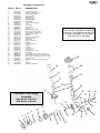
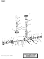
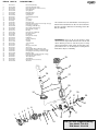
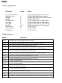
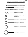
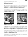
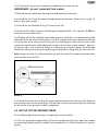
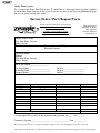
ZX
Flathead VI
DS-IV
50D
Regulator Service Manual
For Zeagle Scuba Regulator Models: 50D, DS-IV, Flathead VI 1st
Stages and ZX 2nd Stage, ZX Octo
Flathead-VI 1st Stage Parts
ITEM #
1
2*
3
4
5
6
7
8
9*
10
11
12*
13*
15*
16
17
18*
19
20*
21
22*
23*
24
25
26
27
28
29
30
31
32*
33*
34*
35
42
43
44
45
PART #
DESCRIPTION......
341-0149-CL
341-0121-MC
341-0148-AA
341-0119-KA
341-0103-CD
341-0122-CD
341-0140-VH
341-0104-CD
341-0105-TA
341-0106-VH
341-0109-CD
341-0108-JA
160-0009-N9
160-0011-N7
341-0127-CD
341-0128-CD
160-0012-N9
341-0129-AA
160-0111-N7
341-0112-CD
341-0139-BA
160-0011-N7
341-0142-AA
341-0115-AA
341-0117-LA
341-0111-CD
341-0113-DL
341-0146-SA
341-0107-VH
341-0141-VA
160-0006-N7
160-0905-N9
160-0016-N7
341-0151-CL
341-0145-CL
341-0147-AA
341-0150-SA
341-0152-SK
Environmental End Cap
Hydrostatic Diaphragm (clear)
Label (for Flathead-VI)
Hydro-Transmitter
Spring Adjuster
Diaphragm Clamp
Regulating Spring
Spring Carrier
Internal Diaphragm (black)
Lifter
Seat Support
Seat (orifice)
O-ring (for seat)
O-ring (for LP port plugs)
LP Port Plug (includes O-ring)
HP Port Plug (includes O-ring)
O-ring (for HP port plugs)
DIN Cap
O-ring (for inlet of DIN bolt)
Din Connector Bolt
Conical Filter
O-ring (for filter & bolt)
DIN Wheel
Yoke Knob Assembly
Dust Cap
Yoke Bolt
Yoke, Satin Finish
Saddle Spacer
HP (high pressure) Valve
Valve Spring
O-ring (smallest O-ring in HP balance plug)
O-ring (middle sized O-ring on HP balance plug)
O-ring (largest sized O-ring on HP balance plug)
HP Balance Plug
Body, Satin Finish (for Flathead-VI 1st stage)
Label
Trim Ring
Washer (for DIN Wheel)
* An asterisk next to the Item Number
means that part is included in the Standard
Service Kit. The Service Kit Part # for the
1st Stage is 345-1000. The 2nd Stage
Service Kit Part # is 345-2000.
25
26
19
20
27
21
22
28
23
24
29
Flathead VI First Stage
Assembly
35
33
31
30
Yoke Model: 310-4110
DIN Model: 310-4120
12
13
18
6
34
32
44
5
1
2
3
15
4
11
9
7
8
10
42
17
16
43
25
19
26
20
21
27
22
23
24
28
38
37
31
39
33
41
29
1
4
2
5
6
3
32
15
18
36
11
9
7
8
10
13
30
16
17
12
50D First Stage Assembly
Go to next page for Item Numbers.
Yoke Model: 310-2110
DIN Model: 310-2120
40
ITEM #
1
2*
3
4
5
6
7
8
9*
10
11
12*
13*
14
15*
16
17
18*
19
20*
21
22*
23*
24
25
26
27
28
29
30
31
32*
33*
34*
35
36
37*
38
39
40
41
PART #
DESCRIPTION......
341-0118-SA
341-0121-MC
341-0144-AA
341-0119-KA
341-0103-CD
341-0122-CD
341-0140-VH
341-0104-CD
341-0105-TA
341-0106-VH
341-0109-CD
341-0108-JA
160-0009-N9
341-0101-CL
160-0011-N7
341-0127-CD
341-0128-CD
160-0012-N9
341-0129-AA
160-0111-N7
341-0112-CD
341-0139-BA
160-0011-N7
341-0142-AA
341-0115-AA
341-0117-LA
341-0111-CD
341-0113-DL
341-0116-KA
341-0107-VH
341-0141-VA
160-0006-N7
160-0905-N9
160-0016-N7
341-0110-CD
341-0123-CL
160-0024-N7
341-0124-CL
341-0125-GA
160-0019-N7
341-0120-CD
Environmental End Cap
Hydrostatic Diaphragm (clear)
Label (specify model to customer service)
Hydro-Transmitter
Spring Adjuster
Diaphragm Clamp
Regulating Spring
Spring Carrier
Internal Diaphragm (black)
Lifter
Seat Support
Seat (orifice)
O-ring (for seat)
Body, Satin Finish (for DS-IV, non-swivel style 1st stage)
O-ring (for LP port plugs)
LP Port Plug (includes O-ring)
HP Port Plug (includes O-ring)
O-ring (for HP port plugs)
DIN Cap
O-ring (for inlet of DIN bolt)
Din Connector Bolt
Conical Filter
O-ring (for filter & bolt)
DIN Wheel
Yoke Knob Assembly
Dust Cap
Yoke Bolt
Yoke, Satin Finish
Spacer
HP (high pressure) Valve
Valve Spring
O-ring (smallest O-ring in HP balance plug)
O-ring (middle sized O-ring on HP balance plug)
O-ring (largest sized O-ring on HP balance plug)
HP Balance Plug
Body, Satin Finish (for 50D, swivel style 1st stage)
O-ring (for 50D body to turret)
Turret, Satin Finish
Thrust Washer
O-ring (for turret to turret bolt)
Turret Bolt
* An asterisk next to the Item Number means that part is
included in the Standard Service Kit. The Service Kit Part
# for the 1st Stage is 345-1000. The 2nd Stage Service Kit
Part # is 345-2000.
IMPORTANT: Items 14, 28, 36, and 38 had a shiny
chrome finish in early models rather than the current satin
chrome finish. If you want to order these parts in a shiny
chrome finish instead of satin, change the last letter in the
part number from “L” to ”D”.These parts in a shiny chrome
finish will be subject to availability.
25
26
19
20
27
21
22
28
23
29
24
33
31
35
30
13
12
18
6
34
32
5
2
3
4
15
1
11 14
17
16
9
7
8
10
DS-IV First Stage Assembly
Yoke Model: 310-4110
DIN Model: 310-4120
TABLE OF CONTENTS
1.0
Introduction
2.0
2.1
2.2
Specifications
Torque Specifications
Model Numbers
3.0
O-rings Reference Chart
4.0
4.1
4.2
4.3
4.4
4.5
4.6
First Stage Procedures
Tools Required for First Stage Servicing
Disassembly of the First Stage
Cleaning and Inspection of the First Stage
Preliminary Assembly of the First Stage
Set-up and Testing of the First Stage
Final Assembly of the First Stage
5.0
5.1
5.2
5.3
5.4
5.5
5.6
5.7
ZX Second Stage Service Procedures
Tools Required for Second Stage Servicing
Disassembly of the Second Stage
Cleaning and Inspection of the Second Stage
Preliminary Assembly of the Second Stage
Set-up of the Second Stage
Final Assembly of the Second Stage
Testing of the Second Stage
6.0
6.1
6.2
6.3
6.4
Helpful Hints
Troubleshooting
Parts Cleaning Recommendations
Commonly Used Cleaning Solutions
Handling Tips
7.0
7.1
7.2
7.3
Warranty and Maintenance Information
Proper Procedure for Warranty Paperwork
Scheduled Maintenance
Order Form (sample)
Before You Begin ...........
Read these instructions completely before you begin servicing the regulator. These instructions are
intended for people who have been AUTHORIZED by Zeagle to repair Zeagle Scuba equipment. If you
are not so authorized - STOP.
FIRST STAGE
The letter at the beginning of the serial number on the first stage indicates the model of that first stage.
If the serial number begins with “A” it is a DS-IV non-swivel first stage (e.g.A001324). If the serial number begins with “B” it is a 50D swivel turret first stage. If the serial number begins with “F” it is a Flathead
VI first stage. For further information, contact Zeagle.
1.0 INTRODUCTION
1.1 The procedures in this manual apply to Zeagle Scuba Regulators.There are two front cover fold outs
inside containing exploded views of the first stages.The one you fold out depends on which model you
are sevicing. One foldout is for the Flathead-VI first stage.The other is for the 50D (swivel) and DS-IV
(non-swivel) model. If you are not sure which first stage you are working on, refer to the pictures on
the front of this manual. Refer to the exploded view as you read the service section of the manual. The
Item Numbers referred to in the service section are those seen in the exploded view.
WARNING
NEVER reuse the diaphragm in the first stage. A used diaphragm will not clamp securely as required. A
used diaphragm may come loose during use, causing a severe regulator malfunction.This is true with all
diaphragm first stages. Failure to read this warning may result in serious injury or death.
NEVER tighten the hose fitting to the first stage with more than 40 in. lbs. (4.5 Nm) of torque.The inlet
hose fitting will be weakened by over tightening. Failure to read this warning may result in serious injury
or death.
NOTE: All Zeagle Scuba Regulators have service kits available which contain the parts which must be
changed at every annual service no matter what their condition. The standard annual service kit part
numbers are shown in the parts list. All other parts not contained in these kits must be inspected by
the technician and changed under warranty only if they have failed due to problems with material or
workmanship.
WARNING
Zeagle Scuba Regulators are manufactured using materials suitable for use with oxygen enriched gases
(i.e. Nitrox, etc.) providing the oxygen content does not exceed 40%. Equipment intended for enriched
air (Nitrox) use must not be used with regular compressed breathing air, or other gases. Regulators
intended for enriched air use can be serviced only by technicians trained by one of the major oxygen
enriched air training agencies. Failure to heed this warning may result in serious injury or death.
1.2 This manual gives breakdowns of regulator parts, equipment specifications, servicing instructions,
troubleshooting recommendations, and guidelines for proper care of Zeagle regulators. This manual is
intended for use only by persons specially trained and authorized to service Zeagle Scuba equipment.
1.3 Anyone attempting to service or repair Zeagle Scuba regulators must have a thorough understanding of the principles of operation of scuba regulators and valves, as well as the appropriate mechanical ability. The technician must be properly trained in the safe use of compressed air and the various
tools and cleaning solutions involved in the procedures outlined in this manual.
1.4 The best source for current part numbers for any of the parts listed in this manual is your current
parts and price list from Zeagle.
1.5 Zeagle conducts seminars on a regular basis to train technicians in proper service and repair procedures for all current Zeagle regulators. In addition, all Zeagle dealers and their staff members are
encouraged to attend the seminars to gain an in-depth understanding of the construction, special features and operation of Zeagle regulators. For information on the dates and locations of upcoming
Zeagle service seminars near you, contact Zeagle or a Zeagle Sales Representative.
NOTE: You must be authorized by Zeagle to work on Zeagle Scuba equipment. You can obtain proper authorization by attending all appropriate seminars given in your area. This is the only way you can
become an authorized Zeagle technician.
1.6
If you have any questions, or need more information, contact your Zeagle Scuba
Sales Representative or Zeagle Customer Service.You can E-mail your technical questions to
[email protected]
2.0 SPECIFICATIONS
Zeagle Models ZX Flathead-VI, ZX 50D and ZX DS-IV
AIR FLOW ......................................
INHALATION RESISTANCE ......
EXHALATION RESISTANCE .....
RECOMMENDED LUBRICANT
33 cu. ft. (935 liters)/min. @ 1 atmosphere
0.9" -2.0" (2.3 - 5.08 cm) w.c. @ 1 atmosphere (adjustable)
0.6" (1.52 cm) w.c. max. @ 1 atm.
LTI Christo-Lube 111®
A. FIRST STAGE REGULATORS
TYPE
WEIGHT .........................................
INTERSTAGE PRESSURE ............
# LOW PRESSURE PORTS ........
# HIGH PRESSURE PORTS .......
MATERIALS ....................................
50D (swivel), DS-IV (non-swivel)
Balanced Diaphragm, Dry Environmental Seal
with Hydrostatic Transmitter
DS-IV 1.9 lb. (.86 kg)
50D 2.1 lb. (.95 kg)
Flathead-VI 2.1 lb. (.99 kg.)
130-145 psi (9-10 bar)(135 psi / 9.3 bar, nominal)
4 (3/8"-24 UNF)
2 (7/16"-20 UNF)
Body -------- CDA-360 Brass
O-rings ----- Buna-N
Seat --------- Advanced Polymer
HP Valve --- Stainless Steel
B. ZX 2nd STAGE REGULATOR
TYPE .................................................
WEIGHT...........................................
HOSE LENGTH ............................
MATERIALS ....................................
Downstream valve, balanced diaphragm,
Diver Adjustable Dive / Pre-Dive Venturi Lever and
Resistance Control Knob
.26 lb. (.54 kg) ( w/o hose )
30 in. (76 mm)
Cover ------------- Flexible Thermoplastic
Case -------------- Rigid Thermoplastic
Poppet Seat ----- Advanced Elastomer
O-rings ----------- Buna-N
Diaphragm ------- Elastomeric Polymer
Exhaust Valve----- Thermoplastic Elastomer
Mouthpiece ------ Silicone
2.1 Torque Specifications:
Description
Item #
Torque
Environmental End Cap
Diaphragm Clamp
DIN Bolt
Yoke Bolt
HP Balance Plug
Turret Bolt
Seat Support
Port Plugs
Hose inlet end
Hose outlet end
2nd Stage Nut
1
6
21
27
35
41
11
16, 17
30
30
7
Hard hand tight (with rag cushioning hand)
25-30 ft/lb (34-40 Nm) (with pin spanner)
20-25 ft/lb (27-34 Nm) (with 1/4” Allen wrench)
20-25 ft/lb (27-34 Nm)
2-3 ft/lb (3-4 Nm) (with 1/4” Allen wrench)
2-3 ft/lb (3-4 Nm) (with 1/4” Allen wrench)
snug metal contact (with 3/16” Allen wrench)
2-3 ft/lb (3-4 Nm) (with 5/32” Allen wrench)
2-3 ft/lb (3-4 Nm)
2-3 ft/lb (3-4 Nm)
1-2 ft/lb (2-3 Nm)
2.2 Model Numbers:
Model #
Description
350-1110
Flathead-VI Yoke 1st Stage, with ZX 2nd Stage - 30” Hose
350-1121
Flathead-VI DIN 1st Stage, with ZX 2nd Stage - 30” Hose + DIN to Yoke Converter
350-2110
50D (swivel turret) Yoke 1st Stage with ZX 2nd Stage - 30" Hose
350-2121
50D (swivel turret) DIN 1st Stage with ZX 2nd Stage - 30" Hose + DIN/Yoke Converter
350-4110
DS-IV (non-swivel) Yoke 1st Stage with ZX 2nd Stage - 30" Hose
350-4121
DS-IV (non-swivel) DIN 1st Stage with ZX 2nd Stage - 30" Hose + DIN/Yoke Converter
320-1110
2nd Stage only, ZX Octopus 2nd Stage with Yellow Cover - 36" Hose
320-1115
2nd Stage only, ZX Standard 2nd Stage with Gray Cover - 30" Hose
310-1110
1st Stage only, Flathead-VI Yoke
310-1120
1st Stage only, Flathead-VI DIN
310-2110
1st Stage only, 50D (swivel turret),Yoke
310-2120
1st Stage only, 50D (swivel turret), DIN
310-4110
1st Stage only, DS-IV (non-swivel) Yoke 1st Stage
310-4120
1st Stage only, DS-IV (non-swivel) DIN 1st Stage
330-0001
DIN to Yoke Converter (allows a DIN equipped regulator to be mounted on a Yoke Valve with no tools.)
1st Stage O- Rings (included in Kit) # 345-1000
160-0006-N7 (32) for stem of HP Valve (30)
160-0009-N9 (13) for seat (Orifice) (13)
160-0011-N7 (15, 23) for LP ports (3) &
inlet filter (1)
160-0012-N9 (18) for HP ports (2)
160-0905-N9 (33) behind thread of HP
balance plug (35)
160-0111-N7 (20) for inlet end of DIN bolt (21)
160-0016-N7 (34) for large end of HP
balance plug (35)
160-0019-N7 (40) for turret to turret-bolt seal
160-0024-N7 (37) for turret to body seal
4.0 SERVICE PROCEDURES FOR THE ZEAGLE MODEL DS-IV (non-swivel) and 50D (swivel-turret) and Flathead-VI (hi-flow) 1st STAGES
4.0.1 Before you begin disassembly of the regulator, test the first and second stages for output pressures
and leakage. Pre-testing in this way will help the technician to pinpoint any specific problems requiring
repair.
4.0.2 The work area must be clean and well lighted, with clean compressed air available to blow sand
and dirt from parts.
4.1 TOOLS & ITEMS REQUIRED FOR FIRST STAGE SERVICING
- Soft-jawed bench vise (bench vise with rubber, plastic, aluminum or plastic jaw inserts)
- 1/4" Allen wrench (p/n 347-0104)
- 3/16" Allen wrench (p/n 347-0316)
- 5/32" Allen wrench (p/n 347-0532)
- 6" or 8" good quality adjustable wrenches
- 15" good quality adjustable wrench
- Zeagle Pin Spanner (p/n 347-0001)
- 1st Stage Annual Service Kit (p/n 345-1000)
- Clean Shop Rags
- LTI Christo-Lube 111® (p/n 347-0111)
- Service Video Tape for this regulator (p/n 347-0101)
- Intermediate Pressure Testing Gauge
4.2 DISASSEMBLY OF THE FIRST STAGE FOR OVERHAUL
To view all of the parts used in the Flathead-VI (hi-flow), 50D (swivel turret), or DS-IV (non-swivel) first
stage, fold out the first page of this manual and view the exploded view appropriate for the model you
are working on.The bracketed numbers in the text refer to the corresponding circled item numbers on
the exploded view drawing.
4.2.1 Use 6” or 8” adjustable wrenches to disconne ct all hoses from the first stage. Pull back the hose
protector from the inlet end of the hose. Inspect the hoses for wear. Pay particular attention to the
area where the metal ferrules meet the rubber hose material. Remove and discard the O-rings from
each end of the hose. Clean, rinse, and blow-dry the interior bores of the hoses. Replace the hoses if
necessary.
4.2.2 Unscrew and remove the environmental end cap (1).
4.2.3 Remove and discard the clear silicone hydrostatic diaphragm (2).
Remove the black hydro-transmitter (4).
Note: The three first stage models covered in this section vary slightly. The minor service procedure
differences are covered. If the regulator you are working on is a 50D (swivel-turret type) skip to instruction 4.2.5 If it is a Flathead-VI (hi-flow) or DS-IV (non-swivel type) continue to the next step listed.
See the pictures on the front cover of this manual if you are not sure which type you have.
4.2.4 Note: For Flathead-VI and DS-IV non-swivel only. Clamp the regulator carefully in a soft-jawed
vise with the HP balance plug (35) facing up. Position the regulator so that the yoke (28) or DIN wheel
(24) is preventing the regulator from rotating as the HP balance plug is loosened. Use a 1/4” Allen
wrench to loosen and remove the HP balance plug assembly (30, 31, 32, 33, 34, and 35) from the body
(14). See Photo #1. Now skip to step 4.2.6
Photo 1 HP Balance Plug Assembly removal
Flathead-VI or DS-IV (DS-IV shown)
Photo 2 Turret Bolt Assembly removal
(50D only)
4.2.5 Note: This step is for the 50D swivel model only. Clamp the regulator carefully in a soft-jawed
vise with the turret bolt (41) facing up. Position the regulator so that the yoke (28) or DIN wheel (24)
is preventing the regulator from rotating as the turret bolt is loosened. Use a 1/4” Allen wrench to
loosen and remove the turret bolt assembly (30, 31, 32, 33, 40 and 41) from the turret (38). See Photo
#2. Remove the turret assembly (37, 38, 39) from the body (36).
4.2.6 If the regulator has severe internal corrosion (due to salt water being forced through the inlet filter), it may be necessary to carefully use a pair of pliers to remove the HP valve (30) from the HP balance plug (35) or turret bolt (41). If so, pull the valve out straight and slowly, taking care not to bend
the stem of the HP valve. Remove and discard all O-rings.
4.2.7 Re-clamp the regulator carefully in a soft-jawed vise with the diaphragm clamping ring (6) facing
up. Position the regulator so that the yoke (28) or DIN wheel (24) is preventing the regulator from
rotating as the diaphragm clamping ring is loosened.
4.2.8 Use a Zeagle pin spanner (p/n 347-0001) installed in the hole in the diaphragm clamping ring (6)
to loosen and remove the diaphragm clamping ring from the body (14 or 36). See photo #3. The heel
of the spanner can be wrapped in tape to help prevent damage to the chrome finish on the clamping
ring.
Photo 3
(50D shown)
4.2.9 Remove the body assembly from the vise.
4.2.10 Use a 1/4” Allen wrench to remove the spring adjuster (5) from the diaphragm clamping ring (6).
Remove the spring (7), spring carrier (8), diaphragm (9) and lifter (10) from the body (14 or 36). Discard
the diaphragm (9).
WARNING
NEVER reuse the diaphragm in the first stage. A used diaphragm will not clamp securly as required. A
used diaphragm may come loose during use, causing a severe regulator malfunction.This is true with all
diaphragm first stages. Failure to read this warning may result in serious injury or death.
4.2.11 Use a 3/16” Allen wrench to remove the seat support (11) from the body.
4.2.12 Remove the seat (12), the seat O-ring (13) and discard both.
4.2.13 Re-clamp the body carefully in a soft-jawed bench vise. Use a 10” adjustable wrench to loosen
and remove the yoke bolt (27) and spacer (29). See Photo # 4. Remove the yoke knob assembly (25)
and the dust cap (26) from the yoke (28).
Note: If the regulator has a DIN wheel, use a 1/4” Allen wrench to remove the DIN bolt (21), and DIN
wheel (24).The Flathead-VI also has a spacing washer (45) behind the DIN wheel.
4.2.14 Remove and discard the inlet filter (22), the filter O-ring (23) and the DIN inlet O-ring (20) if the
regulator is DIN equipped.
4.2.15 Using a 5/32" Allen wrench, remove all remaining port plugs (16, 17) from the body (14 or 36).
Discard the port plug O-rings (15, 18).
4.3 Cleaning and Inspection of the 1st Stage
4.3.1 Clean all metal parts of the first stage in an ultrasonic cleaner or cleaning solution. See Section
6.3 for recommendations on cleaning solutions. Remove the O-rings before cleaning any metal parts
since the soft O-ring material will absorb cleaning energy from the ultrasonic cleaner reducing its effectiveness. If major visible corrosion or deposits exist on parts, use a bristle brush, wooden, or plastic
stick to rub the deposits off. Allowing acidic cleaning solutions to do all of the work if deposits are
severe, will result in damage to internal chrome plating which will make parts even more susceptible to
future corrosion.
4.3.2 Remove the regulator parts from the cleaning solution rinse and blow internal passageways dry
with clean, dry compressed air.
4.3.3 Inspect the diaphragm sealing surfaces and O-ring grooves for scratches or wear. If the regulator
was leaking air because of scratches or wear, replace the parts. If some corrosion deposits persist, carefully wipe them away with a plastic scrubbing cloth. Blow any resulting dust out of the regulator parts.
4.3.4 Roll the stem of the lifter (10) along the square edge of a table or similar surface to check the
stem for straightness. If the head of the lifter wobbles as the stem is rotated, the lifter must be replaced.
The most common cause of lifter stem bending is assembling the regulator in the wrong order. (See
4.4)
4.4 PRELIMINARY ASSEMBLY OF THE FIRST STAGE
Correct order of assembly is extremely important! The diaphragm end MUST be assembled before the HP balance plug end. Incorrect assembly order will result in damage to
the first stage lifter (10) and seat (12). If the diaphragm end of the regulator is opened for
any reason, such as replacing the HP seat (12), the other end of the regulator (turret or
HP balance plug) MUST BE DISASSEMBLED so that the diaphragm end can be re-assembled first.
To determine the identity of each O-ring in the 1st Stage Service Kit, remove them from the bag and
use the O-ring Identification Chart on the front page of this manual. Lay each O-ring over its corresponding picture on the page and read the description. Before installing new O-rings into the regulator,
lightly lubricate the O-rings with LTI Christo-Lube 111®. The most effective way to lubricate the kit Orings is to put them in a small plastic bag with a pea sized amount of LTI Christo-Lube 111®. Rub the
O-rings and grease together in the bag until all the O-rings are coated evenly. Try not to wipe the lubrication off the O-rings when assembling them onto other parts.
4.4.1 Install the yoke bolt (27) into the yoke (28).
4.4.2 Install the spacer (29) onto the yoke bolt (27).
4.4.3 Install the new inlet filter (22) and filter O-ring (23) into the yoke bolt (27).
4.4.4 Hand tighten the yoke, yoke bolt, and spacer into the body (14 or 36).
4.4.5 Note: If the regulator has a DIN connection, install the DIN bolt (21) with a new O-ring (20), DIN
wheel (24) and spacer (29) into the body as described for the yoke assembly. If the regulator is a
Flathead-VI, also install the spacer washer (45)
4.4.6 Place the body (14 or 36 or 42) carefully into a soft-jawed vise so that the yoke bolt or DIN bolt
is facing up.
4.4.7 Tighten the yoke bolt with a 10” adjustable wrench, or the DIN bolt with a 1/4” Allen wrench.
Tighten to 20-25 ft/lb (27-34 Nm)
4.4.8 Re-position the body in the soft-jawed vise until the diaphragm opening faces up. Position the body
so that the yoke or DIN wheel will prevent the body from turning as you tighten the parts (clockwise).
4.4.9 Install the lightly lubricated O-ring (13) onto the seat (12).
4.4.10 Install the seat (12) into the body (14 or 36) from the diaphragm end. The seat installs with the
end with the notch and O-ring groove towards the body.
4.4.11 Use a 3/16” Allen wrench to install the seat support (11) over the seat. Tighten the seat support
until you feel it make full contact with the body. Do not tighten beyond that point.
4.4.12 Install the lifter (10) into the seat support.
4.4.13 Install the new diaphragm (9) into the body.
WARNING
NEVER reuse the diaphragm in the first stage. A used diaphragm will not clamp securly as required. A
used diaphragm may come loose during use, causing a severe regulator malfunction.This is true with all
diaphragm first stages. Failure to read this warning may result in serious injury or death.
4.4.14 Place the spring carrier (8) onto the center of the diaphragm.
4.4.15 Place the main spring (7) onto the spring carrier (8).
4.4.16 Screw the spring adjuster (5) about two turns into the diaphragm clamping ring (6) (from the outside end of the diaphragm clamping ring).
4.4.17 Place the diaphragm clamping ring over the top of the main spring (7) carefully to avoid pushing
the spring and spring carrier out of position on the center of the diaphragm. Tighten the ring down by
hand as far as possible.
Use the pin spanner wrench (Zeagle p/n 347-0001) to tighten the diaphragm clamping ring the rest of
the way down. Tighten to 25-30 ft/lb (34-40 Nm) torque or until the edge of the diaphragm clamping
ring and the body meet metal to metal. This is essential to ensure that the diaphragm is securely clamped. Use an old 1st Stage diaphragm as a cushion under the spanner to prevent marks from
being made on the diaphragm clamping ring.
4.4.18 Turn the body over carefully and re-clamp it in the soft-jawed vise so that the turret or HP balance plug end (depending on model) is faced up.
4.4.19 Note: Steps 4.4.20 to 4.4.24 are for the 50D (swivel) model only. Skip to step 4.4.25
if you are working on a DS-IV (non-swivel). Lightly lubricate the new O-rings from the annual
service kit with LTI Christo-Lube 111®. Install O-ring (37) onto the body (36). Install O-rings (32, 33,
and 40) onto the turret bolt (41).
4.4.20 Lightly lubricate the stem of the HP valve (30). Snap the end of the spring (31) over the ledge
on the HP valve. Insert the valve and spring into the turret bolt (41).
4.4.21 Install the turret (38) onto the body (36). Re-lubricate the cleaned white thrust washer (39) and
install it into the turret (38).
4.4.22 Install the turret bolt and valve assembly onto the end of the regulator. Take care to insure that
the HP valve (30) fits over the stem of the lifter (10) as you install the assembly into the body.
4.4.23 Screw the turret bolt assembly into the body with a 1/4” Allen wrench. Tighten to 2-3 ft/lb (34 Nm) torque or just until you feel firm metal to metal contact stopping the rotation of the parts. Now
skip to step 4.4.30
4.4.24 Note:This and following steps 4.4.26 to 4.4.29 are for the Flathead-VI (hi-flow) and
DS-IV (non-swivel) model only. Lightly lubricate the new O-rings from the annual service kit with
LTI Christo-Lube lll ® and install them onto the HP balance plug (35).
4.4.25 Lightly lubricate the stem of the HP valve (30). Snap the end of the spring (31) over the ledge
on the HP valve.
4.4.26 Insert the valve and spring into the HP balance plug (35).
4.4.27 Install the HP balance plug and valve assembly onto the end of the regulator. Take care to insure
that the HP valve (30) fits over the stem of the lifter (10) as you install the assembly into the body.
4.4.28 Screw the HP balance plug into the body with a 1/4” Allen wrench. Tighten to 2-3 ft/lb (3-4 Nm)
torque or just until you feel firm metal to metal contact stopping the rotation of the parts.
4.4.29 Install the dust cap (26) and yoke knob (25) onto the yoke.
4.4.30 Install new O-rings (15, 18) from the kit onto port plugs (16,17) and install the port plugs into
the appropriate ports.
4.5 SET-UP AND TESTING OF THE FIRST STAGE
NOTE: For safety, always test the first stage regulator with at least one second stage installed. The
demand valve on the second stage acts as a relief valve in case of a malfunction.
4.5.1 Install an intermediate pressure test gauge into one of the low-pressure ports of the first stage,
and a functional 2nd stage into another low pressure port. Plug any remaining open outlet ports with
suitable port plugs.
NOTE: The following test determines the regulator's lock-up pressure (the pressure put out by the
first stage during a no flow condition).
4.5.2 Attach the regulator to a tank valve giving a source pressure of between 2700 and 3500 psig (186240 Bar).
4.5.3 Turn the supply air on slowly while listening for any unusual air leaks. If any are heard, turn the air
off immediately and determine the source of the leak. If no leaks are found, watch the intermediate pressure gauge reading rise as you continue turning the air on slowly. It should stop before 145 psig (10 bar)
since the intermediate pressure has not been set yet.
4.5.4 If the pressure gauge continues to rise above 155 psig (10.4 bar), turn the air supply off immediately and inspect the regulator to determine the cause.
4.5.5 Depress the purge cover fully, then release it several times to clear particles from the regulator,
and to work the internal parts into place. To prevent uncontrolled free flows after pushing the purge
cover, keep the venturi control lever on the second stage in the "-"(negative position)
4.5.6 The pressure range for Zeagle Regulators is 130-145 psi( 9-10 bar) Use a 1/4” Allen wrench
installed into the spring adjuster (5) to change the intermediate pressure. Turn the spring adjuster clockwise in 1/8-turn steps to raise the intermediate pressure, and counter clockwise in 1/8 - turn steps to
lower it. See Photo # 5. Always push the purge cover briefly between each adjustment step. Do not
push on the diaphragm with the tip of the Allen wrench, or a false (higher) reading will occur. The optimal intermediate pressure for Zeagle regulators is 135 psi (9.3 bar), but any setting between 130 and
145 psi (9-10 bar) will provide good stable performance..
4.5.7 After reaching the proper pressure setting, push the purge cover on the second stage again several times and watch how the intermediate pressure reading responds. When the purge cover on the second stage is depressed, the intermediate pressure reading will drop. When the purge cover is released
the pressure should return immediately to the proper lock-up pressure and stay there.
4.5.8 Let the regulator sit with the tank valve turned on for several minutes. The intermediate pressure
reading may rise about 3 psi in the first three seconds after lock-up, but after that it should not rise
more than another 4 psi (.3 bar) in five minutes. If it rises more than 4 psi refer to the Trouble-shooting Section 6.1of this manual.
Note: Never set the output pressure of the first stage above 145 psi (10 bar).
4.6 FINAL ASSEMBLY OF THE FIRST STAGE
4.6.1 To finish installing the end cap on the first stage, the pressure to the first stage must be left on to
position all internal parts properly.
4.6.2 With the regulator pressurized, insert the hydro transmitter (4) into the body assembly.
4.6.3 Install the new clear hydrostatic diaphragm (2) into the recess in the diaphragm clamping ring (6)
over the hydro transmitter. On the Flathead-VI only, install the trim ring (44).
4.6.4 Install the end cap (1) onto the diaphragm clamping ring (6). Use a clean rag to help grasp the end
cap. Tighten the end cap firmly. Use enough force so that the end cap cannot be loosened easily by
hand. On the Flathead-VI only, use the Zeagle Pin Spanner (347-0001) to tighten the cap snuggly. Use an
old 1st Stage diaphram as a cushion under the spanner to prevent marks from being made on the
enviornmental end cap.
4.6.5 Push the clear hydrostatic diaphragm (2) briefly with one finger while watching the intermediate
pressure gauge. The pressure should rise about 1 psi for every pound of force. For example, five or ten
psi (.35 - .7 bar) increase in intermediate pressure when the diaphragm is pushed with five or ten
pounds.
4.6.6 Turn off the supply pressure and depress the purge cover to release the air from the second stage.
When the intermediate pressure drops to zero you should see the clear hydrostatic diaphragm (2) pull
into the body assembly. If the regulator is re-pressurized, the clear diaphragm will push out to the flat
position. If (by mistake) the end cap (1) is loosened and then re-tightened without pressure applied to
the first stage, the clear diaphragm will bulge outwards when the regulator is under pressure. If this condition exists, follow steps 4.6.1 to 4.6.5.
5.0 ZX SECOND STAGE SERVICE PROCEDURES
The procedures covered in this manual section apply to the ZX second stage. To access the exploded
view of this model, fold out the back page of this section of the manual. This second stage is used as a
primary unit, gray or black purge cover and 30” hose (model assembly number 320-1115) and as an
advanced octopus unit, yellow purge cover and 36” hose (model assembly number 320-1110). See the
picture on the front page of this manual section to identify this model type. The serial number for this
model always starts with “H”. The number can be seen by curling back the mouthpiece and looking at
the end of the mouth-tube.
5.1
TOOLS REQUIRED FOR SECOND STAGE SERVICING
- Two good quality 6" or 8" (15 or 20 cm) adjustable wrenches
- Side cutting pliers
- 3/16” Allen Wrench (p/n 347-0316)
- 2nd Stage, Inline Adjusting Tool - 3/16” Hex (p/n 347-0002)
- 2nd Stage Annual Service Kit (p/n 345-2000)
- Clean Shop Rags
- LTI Christo-Lube 111® (p/n 347-0111)
- Service Video Tape for this regulator (p/n 347-0101)
5.2
DISASSEMBLY OF THE SECOND STAGE
WARNING
NEVER tighten the hose fitting to the first stage with more than 40 in. lbs. (4.5 Nm) of torque.The inlet
hose fitting can be weakened by over tightening.
To view the complete parts list of the second stage, fold out the back cover of this manual.
5.2.1 Pull the nut cover (6) off of the nut (7). Use the 6” and 8” adjustable wrenches to loosen the hose
nut from the valve tube (21). Remove the hose assembly (30) from the second stage. Inspect the hose
assembly for any cuts or cracks, especially on the hose at the metal ferrules. Remove and discard the Orings from each end of the hose. Clean, rinse, and blow-dry the interior bores of the hoses. Replace
the hose assembly if any cuts or cracks are found.
5.2.2 Remove the mouthpiece (12) by cutting the two mouthpiece ties (11) with side cutting pliers.
Discard the old mouthpiece ties. Examine the condition of the mouthpiece. Pay particular attention to
the area on top just behind where the old ties tightened. This is a prime area for small holes to develop. If the mouthpiece is in good condition, it can be reused.
5.2.3 Remove the exhaust tee (13) from the case by pulling it back and off the top edge of the retaining flange on the housing. Note: The exhaust tee can be removed more easily if hot water from a tap
is run over and through it for about one minute.
5.2.4 Before removing the exhaust valve (14) from the housing (10), bend the valve over as far as it will
go from the top, bottom, left, and right sides. If it fails to snap back quickly, and does not lie perfectly
flat against the housing exhaust grid, the valve should be replaced. If it does snap back satisfactorily,
remove it by pulling it out with your fingers. Inspect the sealing edges. If they appear smooth, and the
locking tab on the nipple is good, the valve can be reused.
5.2.5 Unscrew the cover ring (1) from the housing (10).
5.2.6 Remove the diaphragm cover (3) and diaphragm (4) from the housing (10).
5.2.7 For future reference, look at the lever (19) at this time. Notice how the pivot end of the lever is
held into the valve tube (21) by two plastic flanges on the housing. Note this positioning for re-assembly.
5.2.8 Hold the diaphragm up to a light source. Gently stretch the diaphragm and look for tears or pinholes. If any are found, replace the diaphragm.
5.2.9 Loosen and remove the nut (7) from the valve tube (21)
5.2.10 Remove the heat sink (8) from the valve tube. Note: On some models instead of a metal heat
sink, there is a plastic bushing (34).
5.2.11 Remove and discard the O-ring (9) from the valve tube.
5.2.12 Turn the spring adjust knob (29) fully counter clockwise until it comes to its stop.
5.2.13 Depress the lever (19) fully onto the valve tube. Grasp the tab of the venturi control lever (16).
While pulling on the venturi control lever, push the valve tube assembly out of the housing (10).
5.2.14 Remove the venturi control lever (16) from the valve tube assembly. Remove and discard the Oring (15) from the venturi control lever.
5.2.15 Turn the spring adjust knob (29) clockwise 1/2 turn. The pin (20) will fall out of the valve tube
or can now be easily removed.
5.2.16 Turn the spring adjust knob assembly (29) counter clockwise to remove it from the valve tube.
Remove and discard the O-ring (28). Note: On some models there is a plastic spring adjuster plug (35)
instead of an adjust knob assembly. Use a 1/4” Allen wrench to remove it.
5.2.17 The balancing chamber (26), spring (25) and piston (23) are removed at this time. They will often
fall out if the valve tube is tipped on its end. If the piston will not fall out, the lever (19) can be moved
through its full arc. If the piston still does not come out a 5/32” (4-5 mm) Allen wrench can be inserted through the male threaded end of the valve tube, through the seat (18) to gently push the piston out.
5.2.18 Remove and discard the O-ring (27) from the outside of the valve tube (21).
5.2.19 The lever (19) should not be removed from the valve tube unnecessarily. However, it can be
removed from the valve body by carefully springing out one of the feet and pivoting it over the valve
tube body. Do not over-bend the lever legs. Straighten the legs if they are bent outward from parallel.
5.2.20 Remove and discard the seating seal (22) from the piston (23).
5.2.21 Remove and discard the very small O-ring (24) from the piston. This can be done by pinching a
section of the O-ring out of the groove with the fingernails. Then flip the O-ring off the end of the piston stem. DO NOT USE SHARP METAL PICKS! Metal tools will damage the O-ring groove, which will
cause a small continuous second stage leak.
5.2.22 Use a 3/16” Allen wrench or the Zeagle 2nd Stage, Inline Adjusting Tool - 3/16” Hex (p/n 3470002) to turn the seat (18) counterclockwise enough turns to fully disengage the threads from the valve
tube (21).
5.2.23 After the threads are disengaged, remove the seat (18) from the valve tube (21) by pulling and
turning counterclockwise at the same time. The seat will usually come out on the end of the Allen
wrench. If it will not come out, it can be pushed out with a soft wooden dowel however, care must be
taken not to damage the seat if it is pushed out.
5.2.24 Remove and discard the O-ring (17) from the seat.
5.3 CLEANING AND INSPECTION OF THE 2nd STAGE
5.3.1 Rinse all plastic and silicone parts in a fresh warm soapy water solution. Rinse with clean warm
water and then blow the parts dry with compressed air to remove any sand and dust particles.
5.3.2 If necessary because of deposits or corrosion, clean all metal parts of the second stage in an ultrasonic cleaner or cleaning solution. See Section 6.3 for recommendations on cleaning solutions.
5.3.3 Inspect the housing (10) for any cracks or nicks. Look particularly closely at the area where the
exhaust valve (14) seals and where the heat sink (8) clamps. Replace the housing if any cracks are found.
5.3.4 Inspect the sealing surface on the seat (18) where the seating seal (22) seals for any nicks or
scratches. Replace the seat (18) if any serious defects are found at the sealing area, or if the threads
appear worn out.
5.3.5 Blow all dust and debris out of the orifice with clean compressed air.
5.3.6 Inspect the exhaust valve (14). Look carefully at the base of the barbed nipple where it comes out
of the middle of the valve. Look for any tearing at this point. Replace the valve if any tears are found.
Replace the valve if nicks or tears are found at the sealing edges of the valve.
5.3.7 During an Annual Overhaul, all parts included in the Annual Service Kit are replaced no matter
what the condition of those parts. Carefully examine all other parts of the second stage for signs of
deterioration. Replace those parts too where necessary.
IMPORTANT: Do not lubricate the O-ring (9) that goes over the valve tube (21) male
threaded end.
5.4 PRELIMINARY ASSEMBLY OF THE SECOND STAGE
5.4.1 Ensure that all parts are clean.To determine the identity of each O-ring in the Second Stage Service
Kit, remove them from the bag and use the O-ring Identification Chart on the back page of this section.
Lay each O-ring over its corresponding picture on the page and read the description.
IMPORTANT: Do not lubricate the O-ring (9) that fits over the end of the valve tube
(21). Before installing new O-rings into the regulator, lightly lubricate the O-rings with LTI Christo-Lube
111® (EXCEPT O-ring (9) that goes over the valve tube (21) male threaded end).
5.4.2 Install the exhaust valve (14) into the case by inserting the nipple into the square hole from the
outside of the case. Reach inside the case and pull the nipple firmly with the fingers until you hear or
feel it "click" into place. Inspect the exhaust valve to see that it is properly seated. Take care not to get
any lubricating grease on the exhaust valve during this procedure.
5.4.3 Install a new O-ring (27) onto the outside of the valve tube (21).
5.4.4 If the lever (19) was removed, carefully re-fit it into the valve tube (21). To orient the lever properly, hold the valve tube with the external threads to the right. Turn the valve tube until you can see the
hole where the air exits the valve tube (indicated by pencil tip in photo). The lever is inserted so that
it leans to the left. See Photo 6. Work the lever into the valve tube one foot at a time so the lever legs
are spread outwards as little as possible.
Photo 6
5.4.5 Insert the new seating seal (22) into the white piston (23).
5.4.6 Install the lubricated small O-ring (24) onto the piston tip.
5.4.7 Install the spring (25) onto the piston and the balance cylinder (26) onto the piston to make the
shuttle valve assembly.
5.4.8 Insert the shuttle valve assembly you have just assembled into the valve tube (21) at the end with
the raised collar (opposite the external threaded end). See Photo 7.
Photo 7
5.4.9 When the shuttle assembly is inserted into the valve tube, it is important that the “L” shaped foot
on the piston section engages properly with the lever tabs that extend through the holes in the valve
tube. In Photo 7, the “L” shaped foot has been highlighted with black marker so you can see the "L"
clearly. The piston is normally all white.
5.4.10 Insert the shuttle valve assembly as shown in Photo 7. Push the assembly all of the way into the
valve tube. The first thing that might hang up on the tabs of the lever is the black seating seal. Wiggle
the lever to get this past the tabs. When the “L” shaped feet get to the lever tabs they will lift the lever
outwards as you push the assembly in.
5.4.11 Install a new well lubricated O-ring (28) onto the spring adjuster knob assembly (29).
5.4.12 Insert the spring adjuster knob assembly into the valve tube over the shuttle valve assembly you
just installed.
5.4.13 Turn the spring adjuster knob assembly clock-wise until the O-ring and flange have passed the
hole where the pin (20) is installed.
5.4.14 Install the pin (20) into the valve tube (21).
5.4.15 Back the spring adjuster knob assembly out counter-clockwise until it tightens against the pin (20)
holding it in place.
5.4.16 Install the new O-ring (15) onto the venturi control lever (16).
5.4.17 While holding the tabs in place in the valve tube with two fingers, depress the lever (19) and the
slide the venturi control lever (16) into place on the valve tube (21).
5.4.18 Install the valve tube assembly into the housing (10). After assembly, make sure that the pivot end
of the lever is held into the valve tube (21) by two plastic flanges on the housing just as they did when
you took the housing apart (see step 5.2.7)
5.4.19 Install the O-ring (9) over the external threaded end of the valve tube (21).
IMPORTANT: DO NOT LUBRICATE THIS O-RING!
5.4.20 Install the heat sink (8) over the external threaded end of the valve tube.
5.4.21 Install the nut (7) over the external threaded end of the valve tube. Tighten the nut snugly 1-2
ft/lb (2-3 Nm) with a wrench.
5.4.22 Install the new lubricated O-ring (17) onto the seat (18).
5.4.23 Use the 3/16” Allen wrench or the 2nd Stage, Inline Adjusting Tool - 3/16” Hex (p/n 347-0002) to
install the seat into the valve tube.
5.4.24 Tighten the seat (18) clockwise with the Allen wrench or Inline tool. It is important that the final
adjustment of the seat leaves the lever with just a little (2-3 degrees of arc) free movement to allow for
the natural wear of the seating seal (22) during the use of the regulator. Adjust the seat (18) in while
watching the tip of the lever (while holding the housing so that the lever is faced upwards). Stop turning the seat (18) as soon as the lever droops, or is loose enough to have 2-3 degrees arc of free play.
See Photo 8. Without this free-play the second stage will begin to hiss slightly after just a few hours use.
Note: Depress the lever (19) while moving the seat with the wrench. This prevents premature indentation and wear of the seal (22).
Photo 8
5.4.25 Install the exhaust tee (13) onto the case by hooking the tee over the flat part of the flange and
then working it over the rest of the flange. This operation is made much easier if the tee is immersed
for one minute in hot tap water to soften it temporarily.
5.5 SET- UP OF THE SECOND STAGE
For the following adjustments, the cover and diaphragm must be removed.
5.5.1 Turn the spring adjust knob assembly (29) out counter-clockwise all the way. Note: Some models
use a plastic spring adjust plug (35) instead of a knob assembly. Use a 1/4” Allen wrench to turn the plastic plug.
5.5.2 Install the new O-rings (31,33) onto the hose assembly (30). Install the hose between a serviced
first stage and the second stage, tighten snugly. Use two wrenches to tighten the second stage hose connection.
Note: Attach the second stage to the overhauled and properly adjusted first stage that it is going to
be used with, mounted on an air tank filled to between 2700 and 3500 psi. Install an intermediate pressure gauge into one of the low-pressure ports.
5.5.3 Carefully turn the air on. After adjusting the second stage as outlined in assembly step 5.4.24 in this
manual, the lever (19) should be should be slightly loose against the “L” shaped foot of the shuttle valve
assembly. See Photo 7. There should be about 1/32” (.8 mm) of free play at the end of the lever. There
should be no air leaking from the second stage with proper intermediate pressure applied to the hose.
If there is air leaking from anywhere on the second stage, correct the problem before going further. The
best test to check for the slightest leaks is to immerse the second stage (with no cover or diaphragm
installed) under pressure in water and look for bubbles indicating a leak. Correct the problem if leaks
are found. See Troubleshooting section 6.1 for help.
5.5.4 Work the lever up and down a few times while the regulator is pressurized. Each time the lever
is released, no air hissing should be heard.
5.6 FINAL ASSEMBLY OF THE SECOND STAGE
5.6.1 Install the diaphragm (4) into the housing (10) so that it sits evenly on the ledge.
5.6.2 Install the diaphragm cover (3) over the diaphragm. Push the cover firmly over the diaphragm so
the diaphragm is seated properly.
5.6.3 Install the purge dome (2) into the cover ring (1).
5.6.4 Screw the purge dome and cover ring into housing. Adjust the purge dome in the cover ring so
that the Zeagle logo sits properly when the cover ring is tightened firmly hand tight.
5.6.5 Install the mouthpiece (12). Be sure to position the mouthpiece so that the overbite where the
top teeth fit, is on the top.
5.6.6 Install the TWO new mouthpiece ties (11) from the service kit. Position one of the tie locks on
each side of the mouthpiece. Tighten both ties securely and cut off excess.
5.6.7 Slide the hose nut cover (6) back over the hose connection.
WARNING
NEVER tighten the hose with more than 40 in. lbs. (4.5 Nm) of torque.The inlet hose fitting can be
weakened by over tightening.
5.7 TESTING OF THE SECOND STAGE
A. INHALATION EFFORT:
5.7.1 With air pressure applied, turn the spring adjuster knob fully counter-clockwise. Move the venturi
lever to the “+” position. Depress and release the purge dome. A large continuous free-flow should
result. Move the venturi lever towards the “-“ position. With no other intervention, by the time you
get the lever 2/3 of the way to the “-“ position the free-flowing should stop. This test shows the regulator is performing as it should. It is not necessary, but you can perform further inhalation tests.
5.7.2 If you have no instrumentation, breathe on the regulator to test the breathing effort. With the
adjusting knob turned fully clockwise, and the venturi lever in the full “-“ (pre-dive) position, the regulator will be relatively hard to inhale on but the purge dome must still purge when depressed.
5.7.3 With the adjusting knob turned fully counter-clockwise, and the venturi lever in the full “+“ (dive)
position the regulator will be easy to inhale on. It is important to note that although the breathing
efforts are very different in these two positions, the ultimate air delivery capacity of the regulator is
essentially the same in either position.
5.7.4 If a water column or water manometer is used to check inhalation effort, it should not exceed 2"
(50 mm) w. c. at cracking with the adjuster knob in the minimum effort position.
Note: These Zeagle regulators have been designed and built to perform with the "Best of the Best" in underwater breathing effort. They also have design features that were influenced by the desire to make the regulator
stable and resistant to freezing and free-flows. The regulator is VERY easy breathing underwater, and yet resists
going into free-flow by just being bumped on the surface.
One important result of this dual personality is that the "Cracking Effort" test on the surface will reveal a relatively high (compared to less stable regulators) cracking effort of 1.4 to 2" (36-51 mm) water column.This is
deliberately designed into the regulator for stability and freezing resistance reasons and IN NO WAY relates to
underwater performance. If the technician wants to lower the cracking effort to the lower end of the range, refer
to the trouble shooting section of this manual (6.1).
5.7.5 Move the venturi adjusting lever (16) through its full range of movement while inhaling on the regulator. You should feel an easier inhalation effort in the “+” position than the “-“ position.
B.
EXHALATION EFFORT:
5.7.6 If you do not use instruments to check the exhalation effort, the flow should feel smooth and
unrestricted.
5.7.7 If you use a water column, it should not exceed 1/2" w.c. (13 mm) at one atmosphere.
5.7.8 Brand new exhaust valves will sometimes adhere slightly to the case, causing a slight increase in
exhalation effort. This condition will disappear with use.
C.
LEAK TEST:
5.7.9 Disconnect the air supply. Purge the regulator of all positive air pressure.
5.7.10 Slowly immerse the second stage in a pan of water with the mouthpiece pointing straight up.
5.7.11 Immerse the regulator until the water is 1/4" to 1/8" (.64 to .32 cm) from the lip of the mouthpiece.
5.7.12 Hold the regulator in this position for one minute and then slowly raise it out of the water.
5.7.13 Tip the regulator mouthpiece downward and watch the inside of the mouthpiece tube. If any
water escapes from the mouthpiece tube, check for the source of the leakage.
D.
INTERMEDIATE PRESSURE AIR LEAKS:
5.7.14 Attach the regulator first stage to a tank short enough to totally submerge the first and second
stage in your filling station cooling water. Adjust the breathing effort knob to the minimum breathing
effort position.
5.7.15 With the tank valve still turned off, flood the second stage completely with water, and then position it mouthpiece up.
5.7.16 Turn the tank air valve on slowly and then watch for any leaks in the first or second stage. If leaks
are seen coming from the second stage, repeat the test with the cover assembly removed. You will be
able to see more clearly exactly where the leak is coming from.
5.7.17 Repair any leaks.
6.0 HELPFUL HINTS
6.1 TROUBLESHOOTING
A. HIGH INHALATION EFFORT AT DEPTH:
POSSIBLE CAUSE
RECOMMENDED ACTION
Inlet filter clogged.
Replace the filter.
Air supply to 1st stage insufficient.
Verify the supply air pressure. Make sure the
customer had the air valve turned all the way
on during the dive.
1st or 2nd stage improperly adjusted
Refer to sections 4.5 and 5.5 of this manual.
A. HIGH INHALATION EFFORT AT SURFACE (cracking effort in air):
POSSIBLE CAUSE
RECOMMENDED ACTION
1st or 2nd stage Refer to sections 4.5 and 5.5 of this manual.
improperly
adjusted.
2nd stage spring The spring (25) can be conditioned to a lower thrust. This is done by squeezing it
force on high down (with a vise or fingers) to near solid height (.350") where the space between
the coils is the same as the thickness of the spring wire. Do not squeeze the spring
end of range
coils completely closed as this will result in too low a cracking effort.
Note:This will lower the cracking effort in air, but will have little or no effect on the
underwater performance. It is usually not necessary and should only be done if the
customer understands that a low cracking effort makes a regulator more prone to
hissing and will probably need more frequent adjusting. If the spring is over
squeezed during this conditioning, so that the coils touch each other, the 2nd stage
may hiss when the adjust knob (29) is turned all of the way out. Turning the knob
in (clockwise) slightly will stop the hissing if this is the case. If the hissing does not
stop, the seat (18) needs adjusting, or the seal (22) needs replacing.
B. CREEPING INTERMEDIATE PRESSURE:
POSSIBLE CAUSE
Damaged or worn 1st stage seat (12).
Damaged or worn seat O-ring (13)
Worn O-ring (32) on HP valve stem.
Scratch in groove where O-ring (32) seals
Nick in sealing surface of HP valve (30)
RECOMMENDED ACTION
Replace
Replace
Replace
Replace
Replace
seat
O-ring
O-ring
HP balance plug (35) or turret bolt (41)
HP valve
C. HISSING FROM SECOND STAGE (but intermediate pressure is OK):
POSSIBLE CAUSE
Damaged or worn 2nd stage seating seal (22)
Nicked seat (18) sealing surfaces
2nd stage demand lever (19) bent too high
Worn O-ring (24) on piston (23)
Damaged O-ring groove on piston (23)
Worn O-ring (17) on seat (18)
Worn O-ring groove on seat (18)
Seat (18) out of adjustment
RECOMMENDED ACTION
Replace seating seal
Replace seat
Replace lever
Replace O-ring
Replace piston
Replace O-ring
Replace seat
Adjust Seat
C.WET BREATHING:
POSSIBLE CAUSE
RECOMMENDED ACTION
Diaphragm improperly installed or hole in
diaphragm
Damaged or loose fitting exhaust valve
Crack in housing (10)
Worn venturi lever O-rings (15, 27)
Scratched or worn venturi lever
sealing surfaces
Scratched or worn housing (10)
sealing surfaces
Improper clearing techniques by diver
Extremely slow breathing allowing water
to build up in housing rather than being
blown out
Check position of diaphragm visually.
Replace if holes found by holding up to a light.
Replace exhaust valve (14)
Replace housing
Replace O-rings (15, 27)
Replace venturi lever (16)
Replace housing
Instruct diver on clearing techniques
Explain this result of slow breathing to diver.
D. HIGH FREQUENCY HUMMING OR BUZZING DURING INHALATION:
POSSIBLE CAUSE
RECOMMENDED ACTION
Harmonic resonance between the springs and
other 1st stage components.
“
“
Remove the main spring (7) flip it over and
re-install.
Replace spring or other components until
resonance stops.
E. LOW FREQUENCY FLUTTERING DURING INHALATION (Above the surface only):
POSSIBLE CAUSE
RECOMMENDED ACTION
Harmonic resonance between the springs and
other 2nd stage components.
“ “
“ “
“ “
“ “
Remove, rotate and re-install diaphragm or switch
diaphragm with another.
Replace seating seal (22)
Remove, rotate and re-install spring (25)
Explain to the customer that this is not harmful to
the regulator, and does not happen underwater.
Move venturi lever (16) towards "-" position until
harmonic resonance stops.
6.2 PARTS CLEANING RECOMMENDATIONS
6.2.1 Regulators that see heavy use, particularly those used in salt water, often require extra effort to
remove dirt and corrosion from the parts of the regulator. Some suggested cleaning solutions are listed
at the end of this section, and there are probably many others being used successfully.The following are
a few general suggestions we can make.
6.2.2 Don't expect your cleaning solution to do all the work in a matter of seconds. If the solution
cleans extremely rapidly, it is probably too strong and is etching the finish on the parts. Use a wooden
or plastic stick or a soft bristle brush to help get rid of the thickest deposits. Take special care not to
damage orifice sealing areas.
6.2.3 Soft parts absorb ultrasonic energy. Remove all O-rings and seals from metal parts before cleaning them. If possible, do not clean plastic parts with the metal parts, or at least understand that every
plastic part you put into the ultrasonic cleaner is slowing down the ultrasonic cleaning process for the
rest of the parts.
6.3 COMMONLY USED CLEANING SOLUTIONS
SOLUTION
COMMENTS
Hot Soapy water
Preferable. Good for plastic, silicone and plated
metal parts.
Ingredients easily available. Approx. 15 min.
cleaning time. May damage chrome finish. Never
use on plastic parts.Vinegar dissolves the plastics
in most polymers making them brittle and more
prone to breakage.
Simple Green ® is a readily available degreaser.
Read the product label for mixing ratios with
water.
Vinegar and water (equal part solution) (weaker solution in Ultrasonic Cleaner)
Simple Green ® and Water
Cleaning solutions recommended by ultrasonic
cleaner manufacturers
6.4
The preferred choice. Check with the manufacturer for strengths and recommended uses for
their cleaners. Choose soap solutions over acidic
HANDLING TIPS
How your customers treat their regulators will directly influence the unit's function and durability.
Following are a few tips that you can pass on to your customers to help assure the durability of their
Zeagle Scuba Regulator.
A. PRE-DIVE CHECKS:
6.4.1 Check the hoses and hose connections for cuts, abrasions or other signs of damage before mounting the regulator on the tank valve. Slide the hose protectors back to inspect the areas of the hose normally covered. Be sure all hose connections are tight.
6.4.2 Just before mounting the regulator on the valve, always turn the valve on briefly to blow any
trapped water out of the valve. There is often salty water trapped in the outlet side of the valve. This
entrapped salt water being blown through the interior of the regulator is the number one source of
internal corrosion and problems with Scuba regulators.
6.4.3 Before turning on the tank air valve, check to make sure that the yoke nut or DIN connection is
tight and the regulator body is aligned properly, with no kinks in the hoses.
6.4.4 Turn the tank valve on slowly and listen for leaks. If any leaks are found, replace or repair parts as
recommended.
6.4.5 Never lift the tank/BCD assembly by the regulator or hoses.
6.4.6 Surface-test the regulator by breathing lightly through the mouthpiece. Depressing the purge button above the water's surface is not an effective or thorough method for testing the function of the regulator.
B. POST-DIVE CARE:
6.4.7 After the dive, blow all water out of the dust cap with clean dry air or dab the water out with an
absorbent cloth and place the cap securely on the regulator inlet. On multiple tank dives, use great care
to keep salt water out of the regulator inlet when tanks are changed. Neglecting these simple procedures is another great cause of corrosion and wear in Scuba regulators. Zeagle's Dry Seal System keeps
all other water-borne contamination out of the first stage body.
6.4.8 With the dust cap securely in place, rinse the first and second stages in clean fresh water. DO
NOT depress the purge button before or during rinsing since this may introduce water into the second
stage and the low-pressure hose. Shake or blow all excess water from the second stage and allow the
entire regulator to air-dry before storing.
6.4.9 Store regulator in a clean bag or storage box, away from sunlight, excessive heat and humidity.
7.0
WARRANTY AND MAINTENANCE INFORMATION
7.1
PROPER PROCEDURE FOR SERVICE PAPERWORK (USA)
7.1.1 Make sure your service location has an adequate supply of the three part “Zeagle Service Order
/ Parts Request” forms. One of these carbon-paper forms is required to get credit for parts used in any
warranty replacement. Contact Zeagle Customer Service for replacement forms.
7.1.2 When the regulator is received from the customer for servicing, verify that they are the original
retail owner of the regulator and that they have had the regulator serviced annually at an Authorized
Zeagle Dealer. You can use your records for this, or receipts they have. If they are not the original
owner or have not had the regulator serviced annually, the warranty is no longer in effect.
7.1.3 Fill out the Zeagle Service Order / Parts Request form. PRINT CLEARLY! If you use service kits,
you only have to use the service kit part number(s) to represent all of the parts in that kit. Parts other
than those in the kits have to be listed individually. The reason for replacing the part also has to be listed on the form.
7.1.4 Attach all of the old parts that were replaced under warranty in a plastic bag and attach it to the
Zeagle Service Order / Parts Request form.
7.1.5 If a body or housing is replaced, the replacement parts will have different new serial numbers. Note
the new serial # in "Description of Part" section of the Zeagle Service Order / Parts Request form.
Write the old number in the Serial # section. The dive store and the customer should keep records of
this serial number change. Use the new numbers in future warranty claims.
7.1.6 Contact Zeagle Customer Service and ask for an RA (Return Authorization) number for each
group of Zeagle Service Order / Parts Request forms you are going to send in.YOU MUST GET A RA#
BEFORE RETURNING ANY PARTS TO ZEAGLE. Due to high volume and a desire to move promised
items through the service department quickly, boxes arriving without a RA# will be put at the end of
the line and will be opened when all other work on properly RA numbered items is finished.This could
delay your items by weeks during peak season!
7.1.7 Write the RA number on the Zeagle Service Order / Parts Request form. Mail the forms with
attached parts bags to Zeagle. You will receive credit or replacement parts ONLY if an RA number is
printed on the form.
7.1.8 If you are servicing Zeagle regulators outside of the United States, your return procedures may be
different. Check with your regional Zeagle Distributor for details.
RA # (fill your RA # in here)
37150 Chancey Road
Zephyrhills, Florida 33541
U. S. A.
7.2
SCHEDULED MAINTENANCE
7.2.1 To keep the owner warranty in effect, your customers must have their regulators inspected and
serviced annually (within six weeks before or after the anniversary of the date of purchase) by an
authorized Zeagle Dealer. Failure to do so invalidates the warranty.
7.2.2 Even with infrequent use, the regulator should be serviced annually to ensure proper performance
and satisfy warranty requirements.
7.2.3 After calling Zeagle Customer Service at (813) 782-5568 for an RA number, Zeagle Scuba parts
and warranty forms are sent to the following address:
Zeagle Scuba Warranty Department
Order Form (sample)
This is a copy of the Service Parts Request Form. The actual form is a three-page carbon copy that is available
by request from Zeagle Customer Service. If you do not have any forms on hand, you may photocopy this page
and use it to receive warranty parts credit.
Service Order / Parts Request Form
This form must be used by the Service Center
for ANY Warranty Servicing
You MUST contact Zeagle for an RA
Number to receive any Warranty Credit
Zeagle Service Center:
City, State (Prov), Country:
Phone / E-mail:
Date Serviced:
37150 Chancey Rd.
Zephyrhills, FL 33541
(813) 782-5568
Fax (813) 782-5569
www.zeagle.com
Technician Name (PRINT):
Technician Number:
Customer Name:
Address:
City, State (Prov), Country:
Phone / E-mail:
RA # (call Zeagle): __________________
1st Stage Model: _____________________
2nd Stage Model: _____________________
Octopus Model: ______________________
Comments:
Part # Installed
Description of Part
345-1000
345-2000
First Stage Service Kit
Second Stage Service Kit
Serial #: ____________________
Serial #: ____________________
Serial #: ____________________
Warranty Item? Y/N
Note: If a body or housing is replaced, note the new serial # in "Description of Part"
Customer Price
Total:
I am the original (first) owner of this equipment being serviced. Yes ____ No _____
Customer's Signature: _____________________________________ Date: _____________
The customer must provide proof of original ownership (receipts, etc.) before any "in Warranty" service can be performed.
Service Center: Be sure this form is completely filled out, signed by the customer and returned to Zeagle for credit on warranty parts.
37150 Chancey Road
Zephyrhills, Florida 33541
U. S. A.
Zeagle Scuba, the Zeagle symbol, ZX, 50D, DS-IV and Flathead VI are trademarks of Zeagle Systems Inc.
All other names are trademarks of their respective owners. All products subject to change without
notice.
Zeagle Web Site www.zeagle.com
Contact Zeagle by E-mail at [email protected]
© 2001 Zeagle Systems Inc.
Printed in USA
Part Number for this Manual (p/n 147-2000)