1
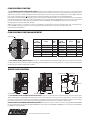
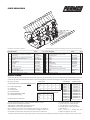
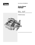
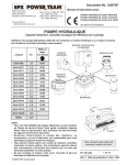
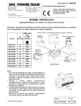
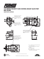
124 SERIES PRIORITY FLOW CONTROL RELIEF VALVE PORT
END COVER
PUMP PORT LOCATIONS
C
Secondary Port rear location,
available in 1/2”, 5/8” or
3/4” SAE Straight Thread
(ODT), Metric Straight Thread
or BSPP
1.63
.75
A
1.88
D
4.00
E
S
P
1.12
.16
5.61
B
Primary Port rear location,
available in 1/2”, 5/8” or
3/4” SAE Straight Thread
(ODT), Metric Straight Thread
or BSPP
1.06
3.16
.25
Primary Port side location
optional, normally plugged
at 1/2” SAE Straight Thread
(ODT), consult factory for
options
2.48
Suction Port side location,
available in 7/8”, 1” or
1-1/4” SAE Straight Thread
(ODT), Metric Straight Thread,
BSPP, SAE Split Flange or
Metric Split Flange
2.48
5.04
2.56
CW view shown, consult factory for all options
PERMCO 1500 Frost Road Streetsboro, Ohio 44241
A. 1.50” ANSI B92.1-96 11 Spline shaft shown.
other shafts available.
B. 1.18” 11 Spline shaft shown, other shafts
available.
C. 6.28” plus gear width.
D. 0.4” plus gear width.
E. 3.250” SAE-A-2 bolt shaft end cover shown,
other shaft end covers available.
FLOW CONTROL FUNCTION
The 124 SERIES PRIORITY FLOW CONTROL COVER allows a constant preset flow of oil from the primary port to a machine function
regardless of changes in pump speed or increased demand from other circuits, however the pump output flow must be equal too or
greater than the primary circuit flow requirements. Output flow from the primary port can be specified from 1 to 12 GPM (3.78 to 45
Liter) and is controlled to within +10% of nominal flow. Flow is controlled by a fixed orifice and is not field adjustable.
Excess flow is available through the secondary port for a downstream machine function or can be plumbed back to tank. The pressure
compensated valve spool allows the primary and secondary ports to be pressurized independently or at the same time. The primary
port has an optional built-in relief valve with settings from 1000 to 3300 PSI (69 to 228 BAR) that relieves to the pump inlet.
Consult factory for optional relief valve settings.
When sizing the pump it is important to take into consideration the desired primary flow, secondary flow, use of secondary flow,
operating RPM, operating temperature, time dumping over relief and other factors to prevent burning of the pump.
Consult factory for assistance.
FLOW CONTROL FUNCTION/ADJUSTMENT
Orifice Spool
Flow
GPM (LPM)
Part #
Drill
Size
Flow
GPM (LPM)
Part #
Drill
Size
1 (3.78)
2 (7.57)
3 (11.36)
4 (15.14)
5 (18.93)
6 (22.71)
514C-L0013-01
514C-L0013-02
514C-LOO13-03
514C-L0013-04
514C-L0013-05
514C-L0013-06
.0699
.0985
.1203
.1387
.1548
.1694
7 (26.50)
8 (30.28)
9 (34.07)
10 (37.85)
11 (41.64)
12 (45.42)
514C-L0013-07
514C-L0013-08
514C-L0013-09
514C-L0013-10
514C-L0013-11
514C-L0013-12
.1828
.1953
.2069
.2180
.2285
.2385
The 124 SERIES FLOW CONTROL COVER pump has an easily changeable controlled flow orifice spool. The orifice spool slides into
the spool bore and can be easily removed for changing the desired system flow or can be drilled out to a larger size for increased flow.
Consult factory for flows and drill sizes not listed.
RELIEF VALVE FUNCTION
Secondary Port
Primary Port
Orifice
Relief Valve
Pump
Adjustment Screw
3.310
No Relief Plug
3.310
The 124 PRIORITY FLOW CONTROL RELIEF VALVE COVER pump has an optional built-in adjustable relief valve with settings from
1000 to 3300 PSI (69 to 228 BAR). This relief valve is meant to be used as the primary port circuit protection. A main system relief
valve is still required for the secondary port adjusted to the systems required pressure setting. Individual port reliefs are still required
for particular functions that have a lower pressure setting requirement than that of the main system relief setting.
NEVER EXCEED THE MAXIMUM PUMP PRESSURE RATING. The 124 series has a maximum pressure rating of 3500 PSI (241 BAR)
for .50” through 1.25” gear widths, 3300 PSI (228 BAR) for 1.50” gear width, 2900 PSI (200 BAR) for 1.75” gear width and 2500 PSI
(172 BAR) for 2.00” gear width.
1500 Frost Road Streetsboro, Ohio 44241
PARTS BREAKDOWN
1
9
10
8
5
7
6
4
3
17
2
18
29
28
24
13
CW tandem unit shown for reference
14
15
21
19
23
Priority Valve Cover (PV) sold as complete unit; parts shown for reference only
Part #
Item # Description
1
2
3
4
5
6
7
8
9
10
11
12
13
14
15
12
16
20
22
25
Shaft End Cover (SAE-A-2-Bolt shown)
Port End Cover (1/2” JIC (S) X 1/2” JIC (P))
Gear Housing
Bearing Carrier (1-1/4” SF X 3/4” JIC shown)
Shaft Gear Set (11 Spline shown)
Gear Set
Connecting Shaft
Thrust Plate
Shaft Seal
Bushing
Dowel Pin (not shown)
Housing Gasket Seal
Thrust Plate Seal
Thrust Plate Backup Seal
Spool (see page 2 for part number)
Qty Item # Description
574-01218
See Below
577-01109--15
576-01127
024-01344-15
996-01103-15
022-01125
947-01105
226-01121
921-01108
280-1971-071
TA-2995-152
947-01107
947-01106
514C-L0013-**
1
1
2
1
1
1
1
4
1
8
8
4
4
4
1
16
17
18
19
20
21
22
23
24
25
26
27
28
29
30
Part #
Spring
O-ring (included with plug part # 18)
Plug ODT 7/8-14
Screw
Hex Nut
O-ring
O-ring
Backup Ring
Poppet Floating
Spring
Plug ODT 3/4-16 (not shown)
O-ring (included with plug part # 26)
Stud
Nut
Washer (not shown)
514C-L0011
565-01598
514C-L0006
514C-L0008
995-01599
995-01600
514-01601
514C-L0007
514C-L0009
W046-39
ZE-0391-11.5
W3-40
W033-1
Qty
1
2
2
1
1
1
1
1
1
1
1
1
4
4
4
MODEL CODING
The pump code for the 124 series priority flow relief valve cover series should be put into the model code as described below. The code
consist of the “PV” which represent the priority valve plus 5 additional characters detailing the porting, flow rate and relief setting.
PV (1) (2) (3) (4) (5)
Sample Model Code: P124A082PVEDFLFZA15-54
1234 5
PV = Priority Valve Cover
(1) = Inlet Port
(2) = Primary Port
(3) = Secondary Port
(4) = Priority Flow Rate in GPM
(5) = Relief Valve Setting
No Relief Plug Part # 514C-L0017
(1) INLET PORT
JIC
Blank
A
7/8”
C
1”
D
1-1/4”
E
SF
A
H
J
K
BSPP
A
N
P
Q
MSF
A
T
U
V
(2) & (3) PRIMARY AND SECONDARY PORT
JIC
BSPP MST
Blank
A
A
A
D
J
1/2”
P
K
5/8”
E
Q
3/4”
F
L
R
PV Cover Assembly Part Number = 124PV + PV Model Code (from above)
Example of PV Cover Assembly Part Number:
124PV-AAAAA or 124PV-AAAAB = Build Program PV Kit
124PV-EDEGF = Customer Specified Part Number
Due to hundreds of variations and combinations consult factory for assistance.
After pump testing PV cover must be disassembled, thoroughly cleaned and
reassembled; residual break-in contamination can cause the PV to malfunction.
MST
A
X
Y
Z
(4) FLOW RATE
1 GPM = A
2 GPM = C
3 GPM = E
4 GPM = G
5 GPM = J
6 GPM = L
7 GPM = N
8 GPM = Q
9 GPM = S
10 GPM = U
11 GPM = W
12 GPM = Y
(5) RELIEF SETTING
No Relief = A
1000 PSI = B
1250 PSI = C
1500 PSI = D
1750 PSI = E
2000 PSI = F
2250 PSI = G
2500 PSI = H
2750 PSI = J
3000 PSI = K
3250 PSI = L
Cap Screws and Nuts : Torque to 120 lb.ft.
1 /2” GW = W1-69 3/4” GW = W1-090
1” GW = W1-090 1-1/4” GW = W1-15
1-1/2” GW = W1-15 1-3/4” GW = W1-099
2” GW = W1-099
Studs = add 2-1/2” to standard flush and
extended stud length for “PV” cover.
The product described herein including without limitation, product features, specification and design are subject to change by Permco without notice
OIL SPECIFICATIONS
Use premium quality hydraulic fluid with a viscosity range of 150-300 SUS (32-65 CST) at 100'F (38'C). Normal operating viscosity
range is between 10-1000 SUS (16-220 CST). Maximum start-up viscosity should not exceed 4000 SUS. Oil should have maximum
anti-wear properties, foam depressant, rust and corrosion inhibitors, oxidation stability of 1500 hours minimum along with a low
flash and fire point. Other desirable characteristics include a high demulsibility (low emulsibility) for separation of water, air and
contaminants, resistance to the formation of sludges, acids, gums, tars and varnishes. Operation in cold conditions requires special
oil consideration so maximum start-up viscosity is not exceeded. Under normal conditions of continuous operation, fluid temperature
should not exceed 150'F (65'C). In no instance should the temperature exceed 185'F (85'C) for mineral based fluids. For water glycol
and invert emulsions information, consult factory.
Maximum inlet vacuum not to exceed 5 IN HG (.17 BAR) or a positive pressure greater than 20 PSI (1.37 BAR). Degassing of the fluid
and subsequent cavitation may occur if these values are exceeded.
FILTRATION
For maximum pump life, the system should be protected from contamination at a level not to exceed 250 particles greater than 10
micrometers per milliliter of fluid. A 10 micrometer return line filter with a B 10 rating of at least 2.2 should provide this level of purity.
A 149 micrometer suction strainer is also suggested for added pump protection, however very high viscosities may dictate not using a
suction strainer. Consult your vehicle body manufacturers service manual for filtration details.
HOSE SELECTION
Selecting the proper hose size and type is critical to proper system operation and hydraulic component longevity. Fluid velocities and
pressure are determining factors, reference your hose manufacturing catalog for actual hose selection.
Recommended Fluid Velocities
Inlet Line............................... 4 Feet per Second
Pressure Line....................... 15 Feet per Second
Return Line........................... 8 Feet per Second
Recommended Hose Type
Inlet Line.................................SAE 100R4
Pressure Line....................... SAE 100R2 or higher
Return/Bypass Line.............. SAE 100R1
SHAFT ALIGNMENT
To assure maximum pump and drive line life proper mounting of the pump is critical. In front mount applications the pump should be
mounted parallel to the engine crankshaft within 1.5'. Universal joints need to be in phase and the drive line should be balanced to the
maximum operating engine RPM. Shaft offset should be between 3-7'.
PTO direct mount units should have anti-seize grease applied to the pump and PTO shaft splines; annual re-applications are suggested
along with semi-annual re-applications for severe duty cycles; refer to your PTO and/or vehicle body maintenance guide.
REPLACEMENT PUMP
If you are replacing a pump on a system that has had a pump failure, it is important that the hydraulic system be thoroughly cleaned
to protect your new pump. Often damaging debris and contamination is still within the system hoses, cylinders, control valves, filters,
and hydraulic tank. The systems main relief valve and system port reliefs can also be affected, a malfunctioning relief or port relief can
severely damage the pump. To insure the hydraulic system is properly flushed and the relief valve are working properly, refer to your
vehicle body manufacturers service manual for hydraulic and filtration system cleaning details.
Before you begin operating the pump, back-off the systems main relief valve to a 0 PSI setting. Run the pump at engine idle RPM’s for
about 5 minutes (or until oil heats up) at 0 PSI with all the control valves in the neutral position. If everything seems to function properly
and no unusual noises are heard, gradually adjust the main relief valve to the required system pressure setting. Refer to your vehicle
body manufacturers service manual for adjusting relief valve details. Never exceed the pressure rating of the pump.
Permco
1500 Frost Rd.
P. O. Box 2068
Streetsboro, OH 44241
Phone 330-626-2801
Fax 330-626-2805
e-mail [email protected]
www.permco.com
Copyright © 2009 Permco, all rights reserved
Permco Tianjin Fluidpower Mfg. Co.
Fenghua Industrial Park
9th Avenue
TEDA, China PC: 300457
Permco (TianJin) Hydraulics Inc., Ltd.
236 Jinbindadao Free Trade Zone
TianJin Port, China
e-mail [email protected]
www.permcotj.com
© 2009 Bulletin #09-124PV-SM