1
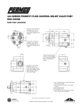
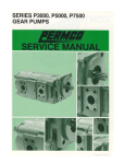
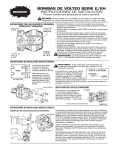
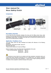
VERSA-PAK FLOW CONTROL/UNLOADER
REFUSE PUMP SYSTEM
Outlet Port
1-1/4” Split Flange
SAE J518, Code 61
PUMP PORT LOCATIONS
Inlet Port Split Flange
SAE J518, Code 61
Model 24 thru 28 = 1-1/2”
Model 32 thru 47 = 2”
Test Port
SAE J1926/1
9/16-18 (-6 ORB)
Solenoid Valve Normally Open
Test Port
SAE J1926/1
9/16-18 (-6 ORB)
Non-Adjustable Relief Valve
Set @ 3100 PSI (214 BAR)
Bypass Port
1-1/4” Split Flange
SAE J518, Code 61
The VERSA-PAK FLOW CONTROL/UNLOADER pump has a built-in non-adjustable relief valve set at 3100 PSI (214 BAR). This relief
valve is not meant to be used as the systems primary circuit protection. A main system relief valve is still required adjusted to the
systems required pressure setting. Individual port reliefs are still required for particular functions that have a lower pressure setting
requirement than that of the main system relief setting.
NEVER EXCEED THE MAXIMUM PUMP PRESSURE RATING. Models VP24, VP28 and VP32 have a maximum pressure rating of 3000
PSI (207 BAR); Models VP37, VP42 and VP47 have a maximum pressure rating of 2500 PSI (172 BAR).
Consult factory for additional information.
ROTATION AND PUMP PORT LOCATIONS
CW Rotation
CCW Rotation
Inlet
Bypass
CCW Rotation
Outlet
Controlled Flow
CF
BYPASS
CF
BYPASS
Bypass
CW Rotation
PERMCO 1500 Frost Road Streetsboro, Ohio 44241
PUMP SELECTION AND OPERATION
The VERSA-PAK FLOW CONTROL/UNLOADER pump uses a modulating element feature that provides a low return to tank pressure
of approximately 20 PSI (1.37 BAR) in the unload “off” mode. When the pump is switched to the “on” mode the modulating element
suspends the unload “off” mode and varies the flow to the preset GPM flow rate. When sizing the pump it is important to remember
that typically the engine is running at high RPM’s, the pump should be sized so the bypass flow is no higher than 50% of the desired
controlled flow.
Example:
System required flow: (a pump flow control setting of 55 GPM (208 LPM) would be used)........................... 55 GPM (208 LPM)
Flow from a VP47 pump operating at 2000 RPM.............................................................................................. 79 GPM (299 LPM)
Bypass flow .......................................................................................................................................................... 24 GPM (91 LPM)
FLOW CONTROL FUNCTION/ADJUSTMENT
BYPASS
Drilled Hole
Part #
Drill
Size
No Orifice Installed
514-01556-25
.2812
514-01556-30
.3125
514-01556-35
.3281
514-01566-40
.3593
514-01566-45
.3750
Blank
25 (95)
30 (114)
35 (132)
40 (115)
45 (170)
CF
Flow Control
Flow
GPM (LPM)
Flow
GPM (LPM)
Part #
Drill
Size
50 (189)
55 (208)
60 (227)
65 (246)
70 (265)
75 (284)
514-01556-50
514-01556-55
514-01556-60
514-01556-65
514-01566-70
514-01566-75
.3906
.4062
.4218
.4375
.4531
.4687
The VERSA-PAK FLOW CONTROL/UNLOADER pump has an easily changeable controlled flow orifice. The orifice screws into the
pressure port and can be easily removed for changing the desired system flow or can be drilled out to a larger size for increased flow.
Consult factory for flows and drill sizes not listed. O-ring (not shown) part number K-2995-920 supplied with orifice.
PUMP SWITCH KIT INSTALLATION
_
+
CW Rotation
1
Battery
2
Ground
CCW Rotation
7
1
4
5
6
3
8
2
10
2
2
2
2
9
Ground 1
Switch Kit Part Number 999-01576
12 Volt Electric/Hydraulic Shift
Includes Items 1 thru 11
*Solenoid lead wires are not polarity sensitive.
Use either when making switch and ground connections.
1 Ground
11
Item #
Part #
Description
Qty
1
2
3
4
5
6
7
8
9
10
11
999-00926
999-00927
999-00928
999-00929
900-01270
999-00931
999-00932
999-00933
999-00934
999-00935
999-00925-30
18-14 Gauge Ring Terminal
16-14 Gauge Butt Splice
16 Gauge Fuse Holder
10 Amp Fuse
10-18 x 1/2” Self Tap Screw
Adhesive Face Plate
Switch Bracket
Switch Guard
Switch with Light
Female Blade Terminal
30’ 16 Gauge Wire
3
4
1
1
2
1
1
1
1
3
1
1500 Frost Road Streetsboro, Ohio 44241
PARTS BREAKDOWN
13
7
1
2
3
4
5
6
10 11 12
9
8
14 15 23 19
16
17
24
21
22
37
28
31
*Valve assembly not sold seperately.
Item # Description
1
2
3
4
5
6
7
8
9
10
11
12
13
14
15
16
17
Special Outboard Seal
Snap Ring
Outboard Ball Bearing
Seal Retainer
Shaft Seal
O-Ring
Shaft End Cover
SAE-C-4-Bolt Shaft End Cover (Code 4C)
SAE-B-4-Bolt Shaft End Cover Code 4B)
SAE-C-2-Bolt Shaft End Cover (Code 2C)
Plug
Extra Service Ring Seal
Roller Bearing
Unloader Thrust Plate Seal
Unloader Thrust Plate
Shaft Key (for SAE-C-Keyed Shaft)
Gear/Shaft Set (G/S)
SAE-C-Keyed G/S Set 1-1/4” (VP24) (Code 0)
SAE-C-Keyed G/S Set 1-1/2” (VP28) (Code 0)
SAE-C-Keyed G/S Set 1-3/4” (VP32) (Code 0)
SAE-C-Keyed G/S Set 2” (VP37) (Code 0)
SAE-C-Keyed G/S Set 2-1/4” (VP42) (Code 0)
SAE-C-Keyed G/S Set 2-1/2” (VP47) (Code 0)
SAE-C-Spline G/S Set 1-1/4” (VP24) (Code 6)
SAE-C-Spline G/S Set 1-1/2” (VP28) (Code 6)
SAE-C-Spline G/S Set 1-3/4” (VP32) (Code 6)
SAE-C-Spline G/S Set 2” (VP37) (Code 6)
SAE-C-Spline G/S Set 2-1/4” (VP42) (Code 6)
SAE-C-Spline G/S Set 2-1/2” (VP47) (Code 6)
Square Housing Gasket
Dowel Pin
Housing
Housing 1-1/2” Split Flange (VP24)
Housing 1-1/2” Split Flange (VP28)
Housing 2” Split Flange (VP32)
Housing 2” Split Flange (VP37)
Housing 2” Split Flange (VP42)
Housing 2” Split Flange (VP47)
* Seal Kit Part Number VPFCUL-SK
Includes Item(s) 1, 5, 6, 11, 15, 24, 25 and 30
* Item(s) Numbers 19, 28, 31, 32, 33, 34, 35 and
36 are Non-Service Part Items. Consult Factory
Part #
W62-26-75
W85-315
W58-48
QZ-0961
W62-26-10
K-2995-164
SA-0574-3D
RA-0574-3D
UA-0574-3D
S-0280
VA-0558-1XS
Q-0921
280-1774-939
AZ-0947-DVS
W09-27
ZE-0024L-1-12
ZE-0024L-1-15
ZE-0024L-1-17
ZE-0024L-1-20
ZE-0024L-1-22
ZE-0024L-1-25
MD-0024L-1-12
MD-0024L-1-15
MD-0024L-1-17
MD-0024L-1-20
MD-0024L-1-22
MD-0024L-1-25
TA-2995-252
280-1971-033
577-01569-12
577-01569-15
577-01569-17
577-01569-20
577-01569-22
577-01569-25
Qty Item # Description
1
1
1
1
1
2
1
1
3
4
4
2
1
1
2
4
1
18
19
20
21
22
23
24
25
26
27
28
29
30
31
32
33
34
35
36
37
Plug (-6 ORB) (not shown)
Port End Cover
12 Volt Solenoid (not shown)
Relief Valve
5/8” Washer
Cap Screw/Hex
Cap Screw/Hex 5/8-11 x 5” (VP24)
Cap Screw/Hex 5/8-11 x 5-1/2” (VP28)
Cap Screw/Hex 5/8-11 x 5-1/2” (VP32)
Cap Screw/Hex 5/8-11 x 6” (VP37)
Cap Screw/Hex 5/8-11 x 6” (VP42)
Cap Screw/Hex 5/8-11 x 6-1/2” (VP47)
O-Ring 161-90 Duro
O-Ring 125 1.30ID x .103W (not shown)
Alignment Sleeve (not shown)
Orifice Plug (-4 ORB) (not shown)
Valve Body
Orifice (not shown) (25 thru 75 GPM)
Orifice 25 GPM
Orifice 40 GPM
Orifice 45 GPM
Orifice 50 GPM
Orifice 55 GPM
O-Ring 920 (-20 ORB) (not shown)
Spool End Cap
Regulating Spring (not shown)
Orifice Spring Seat (not shown)
Unload Spring (not shown)
Poppet (not shown)
Spool (not shown)
Cap Screw/Hex
Cap Screw/Hex 5/8-11 x 8” (VP24)
Cap Screw/Hex 5/8-11 x 8” (VP28)
Cap Screw/Hex 5/8-11 x 8-1/2” (VP32)
Cap Screw/Hex 5/8-11 x 8-1/2” (VP37)
Cap Screw/Hex 5/8-11 x 9” (VP42)
Cap Screw/Hex 5/8-11 x 9” (VP47)
Part #
W046-38
592-01542
999-01557
999-01558
W033-2
W1-14
W1-78
W1-78
W1-65
W1-65
W1-89
K-2995-2235
K-2995-125
514-01549
514-01554
514-01543
514-01556-25
514-01556-40
514-01556-45
514-01556-50
514-01556-55
K-2995-920
514-01553
216-01547
514-01552
216-01548
514-01551
514-01550
Qty
2
1
1
1
8
4
1
1
1
1
1
1
1
1
1
1
1
1
1
4
W1-81
W1-81
W1-990
W1-990
W1-351
W1-351
* Torque Relief Valve and Solenoid to 20 Foot Pounds
* Torque Coil Nut to 5 Foot Pounds
* Torque Orifice Plug to 86 Foot Pounds
* Torque Cap Screws to 200 Foot Pounds
The product described herein including without limitation, product features, specification and design are subject to change by Permco without notice
OIL SPECIFICATIONS
Use premium quality hydraulic fluid with a viscosity range of 150-300 SUS (32-65 CST) at 100 F (38 C). Normal operating viscosity
range is between 10-1000 SUS (16-220 CST). Maximum start-up viscosity should not exceed 4000 SUS. Oil should have maximum
anti-wear properties, foam depressant, rust and corrosion inhibitors, oxidation stability of 1500 hours minimum along with a low
flash and fire point. Other desirable characteristics include a high demulsibility (low emulsibility) for separation of water, air and
contaminants, resistance to the formation of sludges, acids, gums, tars and varnishes. Operation in cold conditions requires special
oil consideration so maximum start-up viscosity is not exceeded. Under normal conditions of continuous operation, fluid temperature
should not exceed 150 F (65 C). In no instance should the temperature exceed 185 F (85 C) for mineral based fluids. For water glycol
and invert emulsions information, consult factory.
Maximum inlet vacuum not to exceed 5 IN HG (.17 BAR) or a positive pressure greater than 20 PSI (1.37 BAR). Degassing of the fluid
and subsequent cavitation may occur if these values are exceeded.
FILTRATION
For maximum pump life, the system should be protected from contamination at a level not to exceed 250 particles greater than 10
micrometers per milliliter of fluid. A 25 micrometer return line filter with a B 10 rating of at least 2.2 should provide this level of purity.
A 149 micrometer suction strainer is also suggested for added pump protection, however very high viscosities may dictate not using a
suction strainer. Consult your vehicle body manufacturers service manual for filtration details.
HOSE SELECTION
Selecting the proper hose size and type is critical to proper system operation and hydraulic component longevity. Fluid velocities and
pressure are determining factors, reference your hose manufacturing catalog for actual hose selection.
Recommended Hose Type
Recommended Fluid Velocities
Inlet Line............................... 4 Feet per Second
Pressure Line....................... 15 Feet per Second
Return Line........................... 8 Feet per Second
Inlet Line.................................SAE 100R4
Pressure Line....................... SAE 100R2 or higher
Return/Bypass Line.............. SAE 100R1
SHAFT ALIGNMENT
To assure maximum pump and drive line life proper mounting of the pump is critical. In front mount applications the pump should be
mounted parallel to the engine crankshaft within 1.5 . Universal joints need to be in phase and the drive line should be balanced to the
maximum operating engine RPM. Shaft offset should be between 3-7 .
PTO direct mount units should have anti-seize grease applied to the pump and PTO shaft splines; annual re-applications are suggested
along with semi-annual re-applications for severe duty cycles; refer to your PTO and/or vehicle body maintenance guide.
REPLACEMENT PUMP
If you are replacing a pump on a system that has had a pump failure, it is important that the hydraulic system be thoroughly cleaned
to protect your new pump. Often damaging debris and contamination is still within the system hoses, cylinders, control valves, filters,
and hydraulic tank. The systems main relief valve and system port reliefs can also be affected, a malfunctioning relief or port relief can
severely damage the pump. To insure the hydraulic system is properly flushed and the relief valve are working properly, refer to your
vehicle body manufacturers service manual for hydraulic and filtration system cleaning details.
Before you begin operating the pump, back-off the systems main relief valve to a 0 PSI setting. Run the pump at engine idle RPM’s for
about 5 minutes (or until oil heats up) at 0 PSI with all the control valves in the neutral position. If everything seems to function properly
and no unusual noises are heard, gradually adjust the main relief valve to the required system pressure setting. Refer to your vehicle
body manufacturers service manual for adjusting relief valve details. Never exceed the pressure rating of the pump.
Permco
1500 Frost Rd.
P. O. Box 2068
Streetsboro, OH 44241
Copyright © 2008 Permco, all rights reserved
Phone 330-626-2801
Fax 330-626-2805
e-mail [email protected]
www.permco.com
Permco (TianJin) Hydraulics Inc., Ltd.
236 Jinbindadao Free Trade Zone
TianJin Port, China
e-mail [email protected]
www.permcotj.com
© Bulletin #08-FC-SM