1
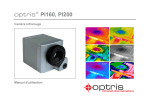
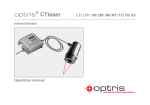
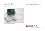
optris® PI NetBox ¯¯¯¯¯¯¯¯¯¯¯¯¯¯¯¯¯¯¯¯¯¯¯¯¯¯¯¯¯¯¯¯¯¯¯¯¯¯¯¯¯¯¯¯¯¯¯¯¯¯¯¯¯¯¯¯¯¯¯¯¯¯¯¯¯¯¯¯¯¯¯¯¯¯¯¯¯¯¯¯¯¯¯¯¯¯¯¯¯¯¯¯¯¯¯¯¯¯¯¯¯¯¯¯¯¯¯¯¯¯¯¯¯¯¯¯¯¯¯¯¯¯¯¯¯¯¯¯¯¯¯¯¯¯¯¯¯¯¯¯¯¯¯¯¯¯¯¯¯¯¯¯¯¯¯¯¯¯¯¯¯¯¯¯¯¯¯¯¯¯¯¯¯¯¯¯¯¯¯¯¯¯¯¯¯¯¯¯¯¯¯¯¯¯¯¯¯¯¯¯¯¯¯¯¯¯¯¯¯¯¯¯¯¯¯¯¯¯¯¯ Mini PC for optris PI series Operators manual CE-Conformity The product complies with the following standards: EMC: Safety Regulations: EN 61326-1:2006 (Basic requirements) EN 61326-2-3:2006 EN 61010-1:2001 The product accomplishes the requirements of the EMC Directive 2004/108/EG and of the Low Voltage Directive 2006/95/EG. Optris GmbH Ferdinand-Buisson-Str. 14 D – 13127 Berlin GERMANY Tel.: +49-30-500 197-0 Fax: +49-30-500 197-10 E-mail: [email protected] Internet: www.optris.com Read the manual carefully before the initial start-up. The producer reserves the right to change the herein described specifications in case of technical advance of the product. References to other chapters are marked as [► ...]. Warranty Each single product passes through a quality process. Nevertheless, if failures occur please contact the customer service at once. The warranty period covers 24 months starting on the delivery date. After the warranty is expired the manufacturer guarantees additional 6 months warranty for all repaired or substituted product components. Warranty does not apply to damages, which result from misuse or neglect. The warranty also expires if you open the product. The manufacturer is not liable for consequential damage or in case of a non-intended use of the product. If a failure occurs during the warranty period the product will be replaced, calibrated or repaired without further charges. The freight costs will be paid by the sender. The manufacturer reserves the right to exchange components of the product instead of repairing it. If the failure results from misuse or neglect the user has to pay for the repair. In that case you may ask for a cost estimate beforehand. optris PI NetBox – E2013-01-A 1 Content Page Description Scope of Supply Scope of Supply (Lightweight version) Maintenance Cautions Technical Data General Specifications Electrical Specifications Installation Controls and Connections Protective Housing 3 3 4 4 4 5 5 5 6 7 8 Page Operation Status LEDs Ethernet Direct Communication Ethernet Network Communication Stand-alone Operation Connection to a Network Device Point-to-Point Connection optris PI NetBox – E2013-01-A 2 9 9 10 11 13 14 14 Description The optris PI NetBox is a miniaturized PC which expands the optris PI series to a stand-alone solution or which works as a USB to Ethernet converter. This mode generates larger possible distances between process (PI camera) and process control (PC). The PI NetBox includes a Windows XP Professional operating system that allows the user to install additional software. The housing of the PI NetBox is made of anodized aluminum – the optional NetBox protection housing supports the usage in industrial environments (IP65/ NEMA-4 rating). Scope of Supply (Standard version) PI NetBox incl. micro SDHC card (8 GB) Power supply (100-240 VAC / 24 VDC) TVout adapter cable Ethernet cable USB Rescue stick (2 GB) Rail mount adapter Operators manual optris PI NetBox – E2013-01-A 3 Scope of Supply (Lightweight version) PI NetBox incl. micro SDHC card (8 GB) Power supply (100-240 VAC / 24 VDC) Power cable (with open ends for direct connection to a Lithium battery) Video adapter cable Ethernet cable USB Rescue stick (2 GB) Operators manual Maintenance The housing of the NetBox can be cleaned with a soft, humid tissue moistened with water or a water based cleaner. PLEASE NOTE: Never use cleaning compounds which contain solvents. Take care that no moisture infiltrates into the housing. Cautions Take care that no foreign substances penetrate into the venting slots of the PI NetBox. In case of problems or questions which may arise when you use the NetBox, please contact our service department. Please use only the threads in the housing or the supplied rail mount adapter for mechanical installation of the PI NetBox. Avoid mechanical violence – this may destroy the system (expiry of warranty). optris PI NetBox – E2013-01-A 4 Technical Data General Specifications Operating temperature Storage temperature Relative humidity Material (housing) Dimensions Weight 0...50 °C -20...75 °C 10...95 %, non condensing Anodized aluminum 113 mm x 57 mm x 39 mm (L x W x H) 280 g Vibration Shock Operating system IEC 68-2-6: 3G, 11 – 200 Hz, any axis IEC 68-2-27: 50G, 11 ms, any axis Windows XP Professional Electrical Specifications Power supply Power consumption Cooling 8...48 VDC or Power over Ethernet (PoE/ 1000BASE-T) 9,5 W (+ additional 2,5 W for PI camera) passive (active via integrated fan for ambient temperatures > 50 °C Board Processor ROM RAM Ports COM Express mini embedded board ® TM Intel Atom Z530/ 1,6 GHz 2 GB SSD 512 MB (DDR2, 533 MHz) 3x USB 2.0 1x Mini-USB 2.0 (slave mode) VGA/ TVout Ethernet (Gigabit Ethernet) microSDHC card (up to 32 GB) 6x Status LEDs (L1-L6) Extensions Additional functions optris PI NetBox – E2013-01-A 5 Installation The PI NetBox can be mounted easily on a DIN rail (TS35) according EN50022 using the supplied rail mount adapter. For this purpose please screw the 4 screws (M4) into the designated holes on the upper side of the NetBox housing. Now you can place the rail mount adapter on the housing and fix it with the 4 nuts. On the bottom side of the NetBox housing you will find 4 holes M2,5 which also can be used for mounting. Dimensions PI NetBox optris PI NetBox – E2013-01-A 6 Controls and Connections 1 2 3 4 5 6 7 8 Mounting holes for rail mount adapter USB 2.0 connection Ethernet connection Power supply connection Mode switch (S1/ S2) Mini USB connection (slave mode) Status-LEDs (L1-L6) microSDHC card slot 9 10 11 12 Cooling fan 2x USB 2.0 connections VGA-/ TVout-connection Switch VGA/ TVout optris PI NetBox – E2013-01-A 7 Protective Housing IP65 Protective housing (Alu die-cast) optris PI NetBox – E2013-01-A 8 Operation The PI NetBox can be used in three different operation modes: 1. Converter USB – Ethernet with direct connection to a PC (point-to-point connection) 2. Converter USB – Ethernet with connection of a PC via a network or via the internet 3. Stand-alone operation with a PI camera For powering the NetBox you either can use the supplied power adapter or a suitable industrial power supply with a voltage output between 8 VDC and 48 VDC [► Technical Data]. Alternatively the PI NetBox can also be powered via the Ethernet cable (PoE – Power over Ethernet). For this purpose a PoE injector is needed [part#: ACPIPOE]. Status LEDs The PI NetBox is equipped with 6 status LEDs (L1-L6). optris PI NetBox – E2013-01-A 9 Ethernet Direct Communication Please connect your imager with the supplied USB connection cable with the PI NetBox. Please connect your PC with an Ethernet cable with the NetBox. Now connect the power supply to the NetBox and to the mains. The NetBox will start to boot the system and should be ready to use after 2-3 minutes. You can check the status with the LEDs. At proper functioning now L1 and L5 should light up. Ethernet direct connection (point-to-point connection)/ PI NetBox powered via power supply If you use a PoE injector the power supply for the NetBox is not needed. In this case please connect the PoE injector as shown in the drawing below. At proper functioning now L1, L2 and L5 should light up. Follow the steps according chapter ► Connection to a Network Device/ Point-to-Point Connection. optris PI NetBox – E2013-01-A 10 Ethernet direct connection (point-to-point connection)/ PI NetBox powered via PoE injector Ethernet Network Communication Please connect your imager with the supplied USB connection cable with the PI NetBox. Please connect the Ethernet connection of the NetBox with a network or internet (via a router e.g.). Now connect the power supply to the NetBox and to the mains. The NetBox will start to boot the system and should be ready to use after 2-3 minutes. You can check the status with the LEDs. At proper functioning now L1 and L5 should light up. If you use a PoE injector the power supply for the NetBox is not needed. In this case please connect the PoE injector as shown in the drawing below. At proper functioning now L1, L2 and L5 should light up. Follow the steps according chapter ► Connection to a Network Device/ Ethernet network communication. optris PI NetBox – E2013-01-A 11 Ethernet network connection/ PI NetBox powered via power supply Ethernet network connection/ PI NetBox powered via PoE injector optris PI NetBox – E2013-01-A 12 Stand-alone Operation optris PI NetBox – E2013-01-A 13 Connection to a Network Device Point-to-Point Connection The communication with the NetBox is done via the TCP/ IP protocol (Transmission Control Protocol/ 1) Internet Protocol). The NetBox can get its IP address (Internet Protocol address) either from a DHCP server or it can work with a fixed IP address. On a direct connection to a PC both, the NetBox as well as the PC must use a fixed IP address because no DHCP server is available here. The NetBox is using in this case the IP address 168.0.100. On your PC you have to do the following settings once (depending on the operating system the procedure can differ from the here shown – the following description refers to a Windows 7 system): 1. Go to System controls; open Network and Sharing Center. 2. If you have an existing connection to a network (company network e.g.) you should see the following information: If your PC is not connected to any network, please go to Change adapter settings after you opened the Network and Sharing Center. Now go to Local Area Connection, right mouse button: Properties. [continue at item 4] 1) DHCP – Dynamic Host Configuration Protocol: allows the automatic integration of a computer into an existing network. optris PI NetBox – E2013-01-A 14 3. Go to Local Area Connection – the following status screen will be shown. Then go to Properties. 4. Mark Internet protocol Version 4 (TCP/IPv4) and go again to Properties: 5. Please open now the register Alternate Configuration and activate the checkbox User configured. 6. Now you can enter a user defined IP address for your PC. Please take care that the network part of the address has to be identical with the network part of the IP address of the NetBox, thus 192.168.0. For the host part you have to use an address which is different from the one of the NetBox (100), so you may use 1 for example. optris PI NetBox – E2013-01-A 15 After you have made these settings and connected your PC with the NetBox using an Ethernet cable your PC will establish a point-to-point connection. This procedure can take several minutes. In the Network and Sharing Center your network will now be shown up as a non-identified network. Please start now the PIConnect on your PC and open the menu item Tools/ Extended/ Remote devices.... In the window which is appearing you should set a hook on Enable and enter the IP address of the NetBox (192.168.0.100) . Press OK. The software will establish a connection to the remote device (imager) automatically. optris PI NetBox – E2013-01-A 16 If the used imager is connected for the first time to the NetBox the following message appears: Please confirm with Yes. The calibration files will be transferred automatically from your PC to the NetBox and stored there. Now you should see the live picture from the imager on your PC. optris PI NetBox – E2013-01-A 17