1
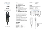
Specifications Warranty Electrical data Nominal current Measuring range 30 A AC peak or DC 30 mA to 30 A DC (accurate) 5 mA to 30 A DC (usable) 500 A for 60 s 100 mV/A ±(2% of reading + 2 mA) 1 mA DC after filtering > 20 A/µs ±1% relative to center Overload capacity Output sensitivity Accuracy Resolution di/dt tracking capability Conductor position sensitivity Temperature 0.1 × specified accuracy/°C coefficient (0 °C to 18 °C, 28 °C to 50 °C) Frequency range DC to 20 kHz (–0.5 dB) Battery type 9 V PP3, MN 1604, 6F22, 6LR61 Battery life 100 hours typical (alkaline) 1 MΩ Min. load impedance All accuracies stated at 23 °C ±5 °C, 70 %RH max. General data Max. conductor size Output cable and connectors Operating temperature Storage temperature (excluding battery) Humidity Altitude Weight Dimensions (H x W x D) Pollution degree 19 mm diameter 2 m long coax. terminated with safety BNC connector +5 °C to +40 °C –20 °C to +70 °C 0 to 80 %RH 0 to 2000 m 300 g 200 mm x 72 mm x 38 mm 2 Standards Safety Measurement category EMC RoHS WEEE EN 61010-1:2010 EN 61010-2-032:2012 CAT IV 600 V, CAT III 1000 V EN 61326-1:2006 EN 61326-2-2:2006 2011/65/EU 2012/19/EU Your current clamp is guaranteed for one year from the date of purchase against defective material or workmanship. If the clamp fails during the warranty period, we shall, at our discretion, repair or replace it with a new or reconditioned unit provided we are satisfied that the failure is due to defective material or workmanship. To make a claim under warranty, return the clamp to us, postage prepaid, with a description of the defect. The use of a battery other than that specified invalidates this warranty. Goods alleged by the buyer to be defective shall not form the subject of any claim for injury, loss, damage, or any expense howsoever incurred, whether arising directly or indirectly from such alleged defects other than death or personal injury resulting from the seller’s negligence. TA234 30 A current clamp No condition is made or to be implied, nor is any warranty given or to be implied as to the life or wear of goods supplied or that they will be suitable for any particular purpose or for use under specific conditions, notwithstanding that such purpose or conditions may be made known to the seller. Pico Technology James House Colmworth Business Park St Neots Cambridgeshire PE19 8YP United Kingdom Tel: Fax: Technical Support: Web: +44 (0) 1480 396395 +44 (0) 1480 396296 [email protected] www.picotech.com Pico Technology and PicoScope are registered trademarks of Pico Technology Ltd. Copyright © 2015 Pico Technology. All rights reserved. DO247-2 Made in Korea User’s Guide Introduction The TA234 is a 30 A current clamp. It has extended measuring jaws that allow measurement in a confined space. When measuring DC, a simple thumbwheel on the clamp allows zero adjustment. Safety information To prevent possible electrical shock, fire, personal injury, or damage to the product, carefully read this safety information before attempting to install or use the clamp. In addition, follow all generally accepted safety practices and procedures for working with and near electricity. The clamp has been designed and tested in accordance with the European standard publication EN 61010-1: 2010, and left the factory in a safe condition. The following safety descriptions are found throughout this guide: A WARNING identifies conditions or practices that could result in injury or death. A CAUTION identifies conditions or practices that could result in damage to the product or equipment to which it is connected. Full-scale measurement range 0 to 20 A AC 0 to 30 A DC Signal voltage limits of EN61010 ± 70 V DC 33 V AC RMS ± 46.7 V pk max. CAUTION. Exceeding the overcurrent protection range can cause permanent damage to the clamp and other connected equipment. WARNING. To prevent electric shock: • • • These safety and electrical symbols may appear on the clamp or in this guide. • Direct current Alternating current • Both direct and alternating current • Possibility of electric shock Caution IEC 61010 overvoltage category Do not dispose of this product as unsorted municipal waste. Contact a qualified recycler for disposal or return it to the manufacturer. WARNING. To prevent injury or death use the clamp only as instructed. Protection provided by the product may be impaired if used other than in the manner specified. CAUTION. To prevent damage, always use and store your current clamp in appropriate environments: see Specifications. Maximum input ranges Observe all ratings and warnings marked on the clamp. The table below indicates the full-scale measurement and overcurrent protection ranges. The full-scale measurement ranges are the maximum currents that can be accurately measured by the clamp. The overcurrent protection range is the maximum current that will not damage the clamp. 500 A for 60 s WARNING. Signals exceeding the voltage limits in the table below are defined as "hazardous live" by EN 61010. Symbols Equipment protected through double or reinforced insulation Overcurrent protection range (current that will not damage) • Do not attempt to measure currents outside the specified full-scale measurement ranges above. Take all necessary safety precautions when working on equipment where hazardous live voltages may be present. This product must be used only by qualified personnel practising applicable safety precautions. Do do not use the clamp if it appears to be damaged in any way, and stop using it immediately if you are concerned by any abnormal behavior. Always ensure that the clamp is removed from any live electrical circuit before removing the battery cover. Do not use in wet or damp conditions, or near explosive gas or vapor. Do not hold the clamp anywhere beyond the tactile barrier: see Fig. 1. Remanence effect When measuring DC current, a remanence effect can temporarily prevent zeroing of the clamp. If this happens, open and close the jaws several times and zero again. If the jaws become magnetized by accidental exposure to a current greater than 30 A, fit the clamp around the conductor in the opposite direction to reverse the magnetization, then remove from the conductor and zero the clamp. Care of the product The product contains no user-serviceable parts. Repair, servicing and calibration require specialized test equipment and must be performed only by Pico Technology or an approved service provider. There may be a charge for these services unless covered by the warranty. CAUTION. Do not tamper with or disassemble the clamp. Internal damage will affect performance. WARNING. When cleaning the clamp, use a soft cloth and a solution of mild soap or detergent in water. To prevent electric shock, do not allow liquids to enter the casing as this will compromise the components inside. Battery replacement The red LOW BAT LED (Fig. 1) will light when the minimum battery voltage is approached. Use the following procedure to replace the battery: 1. Turn off the clamp using the ON/OFF switch and disconnect the output lead from external equipment. 2. Loosen the captive screw that secures the battery cover and lift off the cover. Replace the battery, refit the battery cover and fasten the screw. Operating instructions Current measurement 1. Switch on the clamp using the ON/OFF switch and check that the green POWER LED is lit. 2. The red LOW BAT LED lights when the battery voltage is too low for normal operation. Follow the procedure described below for changing the battery. 3. Connect the output BNC connector to the oscilloscope. 4. Ensuring that the jaws are closed, but not clamped around or placed near a current-carrying conductor, turn the DC ZERO dial until the oscilloscope displays zero signal. Repeat this procedure whenever the zero point drifts due to temperature changes. 5. Clamp the jaws around the conductor, ensuring a good contact between the closing faces of the jaws. 6. Take measurements from the oscilloscope. If using PicoScope, select the “30 A current clamp” probe to display the current in amperes. For other oscilloscopes, apply a conversion factor of 100 mV/A. Positive output indicates that the current is in the direction of the arrow marked on the fixed jaw. 1. 2. 3. 4. 5. 6. 7. 8. Jaws Tactile barrier Jaw trigger Zeroing thumbwheel On/off/range switch Power LED Low battery LED Output connector Figure 1