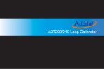
1
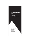
SAFETY
The following symbols appear on the product:
Attention! Refer to Manual.
TA167
Application around and removal from
UNINSULATED HAZARDOUS LIVE conductors
is permitted.
Double/Reinforced Insulation.
AC / DC
CURRENT PROBE
Complies with the relevant European standards.
Do not dispose of this product as unsorted
municipal waste. Contact a qualified recycler for
disposal.
Frequency range ............... DC to 20 kHz (-1 dB)
.......................................... IRMS x f ≤ 400,000
Power supply ..................... 9 V Alkaline battery
PP3, MN 1604
or IEC6LR61
Load impedance (minimum) > 100 kΩ and ≤ 100 pF
General data
Conductor size ................... 32 mm diameter
Output cable and connectors 2 m long coax terminated with
safety BNC connector
Operating temperature ....... 0°C to +50°C
Storage temperature with
Battery removed................. -20°C to +85°C
1)
Accuracy quoted is for conductor in centre of aperture
Read all instructions completely before using
this product.
1
To avoid electric shock:
2
• Use caution during installation and use of this product; high
voltages and currents may be present in circuit under test.
• This product must be used only by qualified personnel
practising applicable safety precautions.
3
4
4
6
• Do not use product if damaged.
• Always connect probe to display device before it is installed
around the conductor.
• Always ensure the probe is removed from any live electrical
circuit, and leads are disconnected before removing the
battery cover.
7
8
9
• Do not hold the probe anywhere beyond the tactile barrier
see Fig 1.
SPECIFICATION
Electrical data
Fig 1
(All accuracies stated at 23°C ± 1°C)
User Manual
Nominal current .................
Measuring range (s) ...........
Overload capacity ..............
Output sensitivity ................
Accuracy1) (0 – 200/1500 A)
Accuracy1) (1500 – 2000 A)
Resolution ..........................
Gain variation .....................
2000 A ACPEAK or DC
2000 A
2200 A (60 s)
10 / 1 mV/A
± 1% of reading ± 100 / ± 500 mA
± 5% of reading
± 100 / ± 500 mA
±0.15% of reading/°C
1.
2.
3.
4.
5.
6.
7.
8.
9.
Jaws
Conventional current direction
Tactile Barrier
Battery cover
Battery cover screw
Jaw trigger
ON/OFF and Range switch
Auto zero button
LED
5
OPERATING INSTRUCTIONS
Switch On
Unclamp the probe from the conductor, turn it off using the On Off switch and disconnect the output leads, from external
equipment.
When the probe is switched on to the required measuring
range, the green LED will illuminate. The LED starts flashing
when the battery voltage is too low for normal operation and
warns the user that it requires changing. This procedure is
described below.
Loosen the captive screw which secures the battery cover. Lift
the cover through 30° and pull it clear of the probe body as
shown in Fig 1. Replace the battery and re-fit the battery cover
and fasten the screw.
Auto Zero
SAFETY STANDARDS
The output zero offset voltage of the probe may change due to
thermal shifts and other environmental conditions. Select the
required measuring range and to null the output voltage
depress the Auto Zero button. Ensure that the probe is away
from the current carrying conductor whilst the probe is being
nulled.
Current Measurement
1. Switch on the probe by selecting the required measuring
range and check that the green LED is lit.
2. Connect the output lead to the oscilloscope,
3. Zero the probe using the Auto Zero button.
4. Clamp the jaws of the probe round the conductor ensuring
a good contact between the closing faces of the jaws.
5. Observe and take measurements as required. Positive
output indicates that the current flow is in the direction
shown by the arrow on the probe.
Auto Power OFF
In order to save battery life, the probe will automatically switch
itself off after approximately 10 minutes. To disable the Auto
power off function, Switch Off the probe and Switch On whilst
pressing the auto zero button. The red LED will illuminate and
the probe will stay ON until switched off again.
Battery Replacement
The green or red LED will flash when the minimum operating
voltage is approached. Refer to Fig 1. Use the following
procedure:
SAFETY WARNING
Before removing the battery cover,
ensure that the probe is disconnected from the
oscilloscope and remote
from any live electrical circuit.
Fit only Type 9 V PP3 Alkaline (MN 1604).
EN 61010-1:2001
EN 61010-2-032:2002
EN 61010-031:2002
300V Cat III, Pollution Degree 2
EMC Standards
EN 61326-2-2:2006
ROHS and WEEE compliant
WARRANTY
Your current probe is guaranteed for one year from the date of
purchase against defective material or workmanship. If the
probe fails during the warranty period, we shall at our
discretion, repair or replace it with a new or reconditioned unit
provided we are satisfied that the failure is due to defective
material or workmanship. To make a claim under warranty, the
probe should be returned to us, postage prepaid, with a
description of the defect. The use of a battery, other than that
specified invalidates this warranty.
Goods alleged by the buyer to be defective shall not form the
subject of any claim for injury, loss, damage, or any expense
howsoever incurred, whether arising directly or indirectly from
such alleged defects other than death or personal injury
resulting from the seller‘s negligence.
No condition is made or to be implied, nor is any warranty given
or to be implied as to the life or wear of goods supplied or that
they will be suitable for any particular purpose or for use under
specific conditions, notwithstanding that such purpose or
conditions may be made known to the seller.
This product is designed to be safe under the following
conditions:
- indoor use
- altitude up to 2000 m
- temperature 0°C to +50°C
- maximum relative humidity 80% for temperatures up to
31°C decreasing linearly to 40% relative humidity at 50°C.
Use of the probe on uninsulated conductors is limited to
300 V ACRMS or DC. and frequencies below 1 kHz.
Safety in its use is the responsibility of the operator who must
be a suitably qualified or authorised person. Ensure that your
fingers are behind the protective barrier see Fig 1 when using
the probe. Always inspect the probe and lead for damage
before use.
To avoid electric shock, keep the probe clean and free of
surface contamination.
Use a cloth moistened with Isopropyl alcohol to clean the
probe, ensure the probe is completely dry before using.
Pico Technology Limited
James House
Colmworth Business Park
St Neots
Cambridgeshire
PE19 8YP
United Kingdom
Tel:
+44 (0) 1480 396395
Fax:
+44 (0) 1480 396296
Technical Support: [email protected]