1
MPLAB® ASM30
MPLAB® LINK30
AND UTILITIES
USER’S GUIDE
© 2005 Microchip Technology Inc.
DS51317E
Note the following details of the code protection feature on Microchip devices:
•
Microchip products meet the specification contained in their particular Microchip Data Sheet.
•
Microchip believes that its family of products is one of the most secure families of its kind on the market today, when used in the
intended manner and under normal conditions.
•
There are dishonest and possibly illegal methods used to breach the code protection feature. All of these methods, to our
knowledge, require using the Microchip products in a manner outside the operating specifications contained in Microchip’s Data
Sheets. Most likely, the person doing so is engaged in theft of intellectual property.
•
Microchip is willing to work with the customer who is concerned about the integrity of their code.
•
Neither Microchip nor any other semiconductor manufacturer can guarantee the security of their code. Code protection does not
mean that we are guaranteeing the product as “unbreakable.”
Code protection is constantly evolving. We at Microchip are committed to continuously improving the code protection features of our
products. Attempts to break Microchip’s code protection feature may be a violation of the Digital Millennium Copyright Act. If such acts
allow unauthorized access to your software or other copyrighted work, you may have a right to sue for relief under that Act.
Information contained in this publication regarding device
applications and the like is provided only for your convenience
and may be superseded by updates. It is your responsibility to
ensure that your application meets with your specifications.
MICROCHIP MAKES NO REPRESENTATIONS OR WARRANTIES OF ANY KIND WHETHER EXPRESS OR IMPLIED,
WRITTEN OR ORAL, STATUTORY OR OTHERWISE,
RELATED TO THE INFORMATION, INCLUDING BUT NOT
LIMITED TO ITS CONDITION, QUALITY, PERFORMANCE,
MERCHANTABILITY OR FITNESS FOR PURPOSE.
Microchip disclaims all liability arising from this information and
its use. Use of Microchip’s products as critical components in
life support systems is not authorized except with express
written approval by Microchip. No licenses are conveyed,
implicitly or otherwise, under any Microchip intellectual property
rights.
Trademarks
The Microchip name and logo, the Microchip logo, Accuron,
dsPIC, KEELOQ, microID, MPLAB, PIC, PICmicro, PICSTART,
PRO MATE, PowerSmart, rfPIC, and SmartShunt are
registered trademarks of Microchip Technology Incorporated
in the U.S.A. and other countries.
AmpLab, FilterLab, Migratable Memory, MXDEV, MXLAB,
PICMASTER, SEEVAL, SmartSensor and The Embedded
Control Solutions Company are registered trademarks of
Microchip Technology Incorporated in the U.S.A.
Analog-for-the-Digital Age, Application Maestro, dsPICDEM,
dsPICDEM.net, dsPICworks, ECAN, ECONOMONITOR,
FanSense, FlexROM, fuzzyLAB, In-Circuit Serial
Programming, ICSP, ICEPIC, Linear Active Thermistor,
MPASM, MPLIB, MPLINK, MPSIM, PICkit, PICDEM,
PICDEM.net, PICLAB, PICtail, PowerCal, PowerInfo,
PowerMate, PowerTool, Real ICE, rfLAB, rfPICDEM, Select
Mode, Smart Serial, SmartTel, Total Endurance, UNI/O,
WiperLock and Zena are trademarks of Microchip Technology
Incorporated in the U.S.A. and other countries.
SQTP is a service mark of Microchip Technology Incorporated
in the U.S.A.
All other trademarks mentioned herein are property of their
respective companies.
© 2005, Microchip Technology Incorporated, Printed in the
U.S.A., All Rights Reserved.
Printed on recycled paper.
Microchip received ISO/TS-16949:2002 quality system certification for
its worldwide headquarters, design and wafer fabrication facilities in
Chandler and Tempe, Arizona and Mountain View, California in
October 2003. The Company’s quality system processes and
procedures are for its PICmicro® 8-bit MCUs, KEELOQ® code hopping
devices, Serial EEPROMs, microperipherals, nonvolatile memory and
analog products. In addition, Microchip’s quality system for the design
and manufacture of development systems is ISO 9001:2000 certified.
DS51317E-page ii
© 2005 Microchip Technology Inc.
MPLAB® ASM30, MPLAB® LINK30
AND UTILITIES USER’S GUIDE
Table of Contents
Preface ........................................................................................................................... 1
Part 1 – MPLAB ASM30 Assembler
Chapter 1. Assembler Overview
1.1 Introduction ................................................................................................... 11
1.2 Highlights ...................................................................................................... 11
1.3 MPLAB ASM30 and Other Development Tools ........................................... 11
1.4 Feature Set ................................................................................................... 12
1.5 Input/Output Files ......................................................................................... 12
Chapter 2. MPLAB ASM30 Command Line Interface
2.1 Introduction ................................................................................................... 17
2.2 Highlights ...................................................................................................... 17
2.3 Syntax .......................................................................................................... 17
2.4 Options that Modify the Listing Output ......................................................... 18
2.5 Options that Control Informational Output .................................................... 28
2.6 Options that Control Output File Creation .................................................... 29
2.7 Other Options ............................................................................................... 30
Chapter 3. Assembler Syntax
3.1 Introduction ................................................................................................... 31
3.2 Highlights ...................................................................................................... 31
3.3 Internal Preprocessor ................................................................................... 31
3.4 Source Code Format .................................................................................... 32
3.5 Constants ..................................................................................................... 35
3.6 Summary ...................................................................................................... 37
Chapter 4. Assembler Expression Syntax and Operation
4.1 Introduction ................................................................................................... 39
4.2 Highlights ...................................................................................................... 39
4.3 Expressions .................................................................................................. 39
4.4 Operators ..................................................................................................... 40
4.5 Special Operators ......................................................................................... 41
© 2005 Microchip Technology Inc.
DS51317E-page iii
MPLAB® ASM30/LINK30 and Utilities User’s Guide
Chapter 5. Assembler Symbols
5.1 Introduction ................................................................................................... 45
5.2 Highlights ...................................................................................................... 45
5.3 What are Symbols ........................................................................................ 45
5.4 Reserved Names .......................................................................................... 45
5.5 Local Symbols .............................................................................................. 46
5.6 Giving Symbols Other Values ...................................................................... 47
5.7 The Special DOT Symbol ............................................................................. 47
5.8 Using Executable Symbols in a Data Context .............................................. 47
Chapter 6. Assembler Directives
6.1 Introduction ................................................................................................... 49
6.2 Highlights ...................................................................................................... 49
6.3 Directives that Define Sections .................................................................... 50
6.4 Directives that Fill Program Memory ............................................................ 54
6.5 Directives that Initialize Constants ............................................................... 56
6.6 Directives that Declare Symbols .................................................................. 59
6.7 Directives that Define Symbols .................................................................... 60
6.8 Directives that Modify Section Alignment .................................................... 61
6.9 Directives that Format the Output Listing ..................................................... 66
6.10 Directives that Control Conditional Assembly ............................................ 67
6.11 Directives for Substitution/Expansion ......................................................... 68
6.12 Miscellaneous Directives ............................................................................ 71
6.13 Directives for Debug Information ................................................................ 73
Part 2 – MPLAB LINK30 Linker
Chapter 7. Linker Overview
7.1 Introduction ................................................................................................... 77
7.2 Highlights ...................................................................................................... 77
7.3 MPLAB LINK30 and Other Development Tools ........................................... 77
7.4 Feature Set ................................................................................................... 78
7.5 Input/Output Files ......................................................................................... 78
Chapter 8. MPLAB LINK30 Command Line Interface
8.1 Introduction ................................................................................................... 83
8.2 Highlights ...................................................................................................... 83
8.3 Syntax .......................................................................................................... 83
8.4 Options that Control Output File Creation .................................................... 84
8.5 Options that Control Run-time Initialization .................................................. 89
8.6 Options that Control Informational Output .................................................... 91
8.7 Options that Modify the Link Map Output ..................................................... 93
DS51317E-page iv
© 2005 Microchip Technology Inc.
Table of Contents
Chapter 9. Linker Scripts
9.1 Introduction ................................................................................................... 95
9.2 Highlights ...................................................................................................... 95
9.3 Overview of Linker Scripts ............................................................................ 95
9.4 Command Line Information .......................................................................... 96
9.5 Contents of a Linker Script ........................................................................... 96
9.6 Creating a Custom Linker Script ................................................................ 107
9.7 Linker Script Command Language ............................................................. 107
9.8 Expressions in Linker Scripts ..................................................................... 122
Chapter 10. Linker Processing
10.1 Introduction ............................................................................................... 129
10.2 Highlights .................................................................................................. 129
10.3 Overview of Linker Processing ................................................................. 129
10.4 Memory Addressing ................................................................................. 131
10.5 Linker Allocation ....................................................................................... 133
10.6 Global and Weak Symbols ....................................................................... 136
10.7 Handles .................................................................................................... 137
10.8 Initialized Data .......................................................................................... 138
10.9 Read-only Data ........................................................................................ 141
10.10 Stack Allocation ...................................................................................... 143
10.11 Heap Allocation ...................................................................................... 144
10.12 Interrupt Vector Tables ........................................................................... 144
10.13 Optimizing Memory Usage ..................................................................... 154
Chapter 11. Linker Examples
11.1 Introduction ............................................................................................... 159
11.2 Highlights .................................................................................................. 159
11.3 Memory Addresses and Relocatable Code .............................................. 160
11.4 Locating a Variable at a Specific Address ................................................ 161
11.5 Locating a Function at a Specific Address ............................................... 161
11.6 Saving and Restoring the PSVPAG Register ........................................... 162
11.7 Locating a Constant at a Specific Address in Program Memory .............. 163
11.8 Locating and Accessing Data in EEPROM Memory ................................ 164
11.9 Creating an Incrementing Modulo Buffer in X Memory ............................ 166
11.10 Creating a Decrementing Modulo Buffer in Y Memory ........................... 166
11.11 Locating the Stack at a Specific Address ............................................... 167
© 2005 Microchip Technology Inc.
DS51317E-page v
MPLAB® ASM30/LINK30 and Utilities User’s Guide
Part 3 – MPLAB LIB30 Archiver/Librarian
Chapter 12. MPLAB LIB30 Archiver/Librarian
12.1 Introduction ............................................................................................... 171
12.2 Highlights .................................................................................................. 171
12.3 MPLAB LIB30 and Other Development Tools .......................................... 172
12.4 Feature Set ............................................................................................... 172
12.5 Input/Output Files ..................................................................................... 172
12.6 Syntax ...................................................................................................... 173
12.7 Options ..................................................................................................... 173
12.8 Scripts ...................................................................................................... 175
Part 4 – Utilities
Chapter 13. Utilities Overview
13.1 Introduction ............................................................................................... 179
13.2 Highlights .................................................................................................. 179
13.3 What are Utilities ...................................................................................... 179
Chapter 14. pic30-bin2hex Utility
14.1 Introduction ............................................................................................... 181
14.2 Highlights .................................................................................................. 181
14.3 Input/Output Files ..................................................................................... 181
14.4 Syntax ...................................................................................................... 182
14.5 Options ..................................................................................................... 182
Chapter 15. pic30-nm Utility
15.1 Introduction ............................................................................................... 183
15.2 Highlights .................................................................................................. 183
15.3 Input/Output Files ..................................................................................... 183
15.4 Syntax ...................................................................................................... 183
15.5 Options ..................................................................................................... 184
15.6 Output Formats ........................................................................................ 185
Chapter 16. pic30-objdump Utility
16.1 Introduction ............................................................................................... 187
16.2 Highlights .................................................................................................. 187
16.3 Input/Output Files ..................................................................................... 187
16.4 Syntax ...................................................................................................... 187
16.5 Options ..................................................................................................... 188
Chapter 17. pic30-ranlib Utility
17.1 Introduction ............................................................................................... 191
17.2 Highlights .................................................................................................. 191
17.3 Input/Output Files ..................................................................................... 191
17.4 Syntax ...................................................................................................... 191
17.5 Options ..................................................................................................... 191
DS51317E-page vi
© 2005 Microchip Technology Inc.
Table of Contents
Chapter 18. pic30-strings Utility
18.1 Introduction ............................................................................................... 193
18.2 Highlights .................................................................................................. 193
18.3 Input/Output Files ..................................................................................... 193
18.4 Syntax ...................................................................................................... 193
18.5 Options ..................................................................................................... 194
Chapter 19. pic30-strip Utility
19.1 Introduction ............................................................................................... 195
19.2 Highlights .................................................................................................. 195
19.3 Input/Output Files ..................................................................................... 195
19.4 Syntax ...................................................................................................... 195
19.5 Options ..................................................................................................... 196
Chapter 20. pic30-lm Utility
20.1 Introduction ............................................................................................... 197
20.2 Highlights .................................................................................................. 197
20.3 Syntax ...................................................................................................... 197
20.4 Options ..................................................................................................... 197
Part 5 – Command-Line Simulator
Chapter 21. SIM30 Command-Line Simulator
21.1 Introduction ............................................................................................... 201
21.2 Highlights .................................................................................................. 201
21.3 Syntax ...................................................................................................... 201
21.4 Options ..................................................................................................... 202
Part 6 – Appendices
Appendix A. Assembler Errors/Warnings/Messages
A.1 Introduction ................................................................................................ 207
A.2 Highlights ................................................................................................... 207
A.3 Fatal Errors ................................................................................................ 207
A.4 Errors ......................................................................................................... 208
A.5 Warnings .................................................................................................... 215
A.6 Messages ................................................................................................... 220
Appendix B. Linker Errors/Warnings
B.1 Introduction ................................................................................................ 221
B.2 Highlights ................................................................................................... 221
B.3 Errors ......................................................................................................... 221
B.4 Warnings .................................................................................................... 226
Appendix C. Deprecated Features
C.1 Introduction ................................................................................................ 229
C.2 Highlights ................................................................................................... 229
C.3 MPLAB ASM30 Directives that Define Sections ........................................ 229
C.4 Reserved Section Names with Implied Attributes ...................................... 230
© 2005 Microchip Technology Inc.
DS51317E-page vii
MPLAB® ASM30/LINK30 and Utilities User’s Guide
Appendix D. MPASM™ Assembler Compatibility
D.1 Introduction ................................................................................................ 231
D.2 Highlights ................................................................................................... 231
D.3 Compatibility .............................................................................................. 231
D.4 Examples ................................................................................................... 234
D.5 Converting PIC18FXXX Assembly Code to dsPIC30FXXXX
Assembly Code .................................................................................... 235
Appendix E. MPLINK™ Linker Compatibility
E.1 Introduction ................................................................................................ 241
E.2 Highlights ................................................................................................... 241
E.3 Compatibility .............................................................................................. 241
E.4 Migration to MPLAB LINK30 ...................................................................... 241
Appendix F. MPLIB™ Librarian Compatibility
F.1 Introduction ................................................................................................ 243
F.2 Highlights ................................................................................................... 243
F.3 Compatibility ............................................................................................... 243
F.4 Examples ................................................................................................... 244
Appendix G. Useful Tables
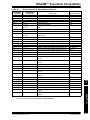
G.1 Introduction ................................................................................................ 245
G.2 Highlights ................................................................................................... 245
G.3 ASCII Character Set ................................................................................ 245
G.4 Hexadecimal to Decimal Conversion ......................................................... 246
Appendix H. GNU Free Documentation License
H.1 Preamble ................................................................................................... 247
H.2 Applicability and Definitions ....................................................................... 247
H.3 Verbatim Copying ...................................................................................... 249
H.4 Copying In Quantity ................................................................................... 249
H.5 Modifications .............................................................................................. 250
H.6 Combining Documents .............................................................................. 251
H.7 Collections of Documents .......................................................................... 251
H.8 Aggregation with Independent Works ........................................................ 252
H.9 Translation ................................................................................................. 252
H.10 Termination .............................................................................................. 252
H.11 Future Revisions of this License .............................................................. 252
Glossary .....................................................................................................................253
Index ...........................................................................................................................261
Worldwide Sales and Service ...................................................................................272
DS51317E-page viii
© 2005 Microchip Technology Inc.
MPLAB® ASM30, MPLAB® LINK30
AND UTILITIES USER’S GUIDE
Preface
NOTICE TO CUSTOMERS
All documentation becomes dated, and this manual is no exception. Microchip tools and
documentation are constantly evolving to meet customer needs, so some actual dialogs
and/or tool descriptions may differ from those in this document. Please refer to our web site
(www.microchip.com) to obtain the latest documentation available.
Documents are identified with a “DS” number. This number is located on the bottom of each
page, in front of the page number. The numbering convention for the DS number is
“DSXXXXXA”, where “XXXXX” is the document number and “A” is the revision level of the
document.
For the most up-to-date information on development tools, see the MPLAB® IDE on-line help.
Select the Help menu, and then Topics to open a list of available on-line help files.
INTRODUCTION
This chapter contains general information that will be useful to know before using 16-bit
language tools. Items discussed include:
•
•
•
•
•
•
Document Layout
Conventions Used in this Guide
Recommended Reading
The Microchip Web Site
Development Systems Customer Change Notification Service
Customer Support
DOCUMENT LAYOUT
This document describes how to use GNU language tools to write code for 16-bit
applications. The document layout is as follows:
Part 1 – MPLAB® ASM30 Assembler
• Chapter 1: Assembler Overview – gives an overview of assembler operation.
• Chapter 2: MPLAB ASM30 Command Line Interface – details command line
options for the assembler.
• Chapter 3: Assembler Syntax – describes syntax used with the assembler.
• Chapter 4: Assembler Expression Syntax and Operation – provides guidelines
for using complex expressions in assembler source files.
• Chapter 5: Assembler Symbols – describes what symbols are and how to use them.
• Chapter 6: Assembler Directives – details the available assembler directives.
© 2005 Microchip Technology Inc.
DS51317E-page 1
MPLAB® ASM30/LINK30 and Utilities User’s Guide
Part 2 – MPLAB LINK30 Linker
• Chapter 7: Linker Overview – gives an overview of linker operation.
• Chapter 8: MPLAB LINK30 Command Line Interface – details command line
options for the linker.
• Chapter 9: Linker Scripts – describes how to generate and use linker scripts to
control linker operation.
• Chapter 10: Linker Processing – discusses how the linker builds an application
from input files.
• Chapter 11: Linker Examples – discusses a number of 16-bit specific linker
examples and shows the equivalent syntax in C and assembly language.
Part 3 – MPLAB LIB30 Archiver/Librarian
• Chapter 12: MPLAB LIB30 Archiver/Librarian – details command line options for
the librarian.
Part 4 – Utilities
• Chapter 13: Utilities Overview – gives an overview of utilities and their operation.
• Chapter 14: pic30-bin2hex Utility – details command line options for
binary-to-hexadecimal conversion.
• Chapter 15: pic30-nm Utility – details command line options for listing symbols in
an object file.
• Chapter 16: pic30-objdump Utility – details command line options for displaying
information about object files.
• Chapter 17: pic30-ranlib Utility – details command line options for creating an
archive index.
• Chapter 18: pic30-strings Utility – details command line options for printing
character sequences.
• Chapter 19: pic30-strip Utility – details command line options for discarding all
symbols from an object file.
• Chapter 20: pic30-lm Utility – details command line options for displaying
information about the MPLAB C30 license.
Part 5 – Command-Line Simulator
• Chapter 21: SIM30 Command Line Simulator – describes the command line
simulator that supports 16-bit tools.
DS51317E-page 2
© 2005 Microchip Technology Inc.
Preface
Part 6 – Appendices
• Appendix A: Assembler Errors/Warnings/Messages – contains a descriptive list
of the errors, warnings and messages generated by MPLAB ASM30.
• Appendix B: Linker Errors/Warnings – contains a descriptive list of the errors
and warnings generated by MPLAB LINK30.
• Appendix C: Deprecated Features – describes features that are considered
obsolete.
• Appendix D: MPASM™ Assembler Compatibility – contains information on
compatibility with MPASM assembler, examples and recommendations for
migration to MPLAB ASM30.
• Appendix E: MPLINK™ Linker Compatibility – contains information on
compatibility with MPLINK linker, examples and recommendations for migration to
MPLAB LINK30.
• Appendix F: MPLIB™ Librarian Compatibility – contains information on
compatibility with MPLIB librarian, examples and recommendations for migration to
MPLAB LIB30.
• Appendix G: Useful Tables – lists some useful tables: the ASCII character set and
hexadecimal to decimal conversion.
• Appendix H: GNU Free Documentation License – details the license requirements
for using the GNU language tools.
© 2005 Microchip Technology Inc.
DS51317E-page 3
MPLAB® ASM30/LINK30 and Utilities User’s Guide
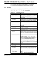
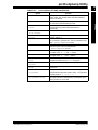
CONVENTIONS USED IN THIS GUIDE
The following conventions may appear in this documentation:
DOCUMENTATION CONVENTIONS
Description
Represents
Examples
Arial font:
Italic characters
Referenced books
MPLAB® IDE User’s Guide
Emphasized text
...is the only compiler...
Initial caps
A window
the Output window
A dialog
the Settings dialog
A menu selection
select Enable Programmer
Quotes
A field name in a window or
dialog
“Save project before build”
Underlined, italic text with
right angle bracket
A menu path
File>Save
Bold characters
A dialog button
Click OK
A tab
Click the Power tab
A key on the keyboard
Press <Enter>, <F1>
Sample source code
#define START
Filenames
autoexec.bat
File paths
c:\mcc18\h
Keywords
_asm, _endasm, static
Command-line options
-Opa+, -Opa-
Bit values
0, 1
Constants
0xFF, ’A’
Italic Courier
A variable argument
file.o, where file can be
any valid filename
Square brackets [ ]
Optional arguments
mpasmwin [options]
file [options]
Curly brackets and pipe
character: { | }
Choice of mutually exclusive
arguments; an OR selection
errorlevel {0|1}
Ellipses...
Replaces repeated text
var_name [,
var_name...]
Represents code supplied by
user
void main (void)
{ ...
}
Text in angle brackets < >
Courier font:
Plain Courier
Icon
This feature supported only in
the full version of the software.
This feature is not supported
on all devices. Devices supported will be listed in the title
or text.
DS51317E-page 4
© 2005 Microchip Technology Inc.
Preface
RECOMMENDED READING
This documentation describes how to use 16-bit language tools. Other useful
documents are listed below. The following Microchip documents are available and
recommended as supplemental reference resources.
Readme Files
For the latest information on Microchip tools, read the associated README files
(ASCII text files) included with the software.
dsPIC® Language Tools Getting Started (DS70094)
A guide to installing and working with the Microchip language tools (MPLAB ASM30,
MPLAB LINK30 and MPLAB C30) for 16-bit devices. Examples using the 16-bit
simulator, and MPLAB SIM30, are provided.
MPLAB® C30 C Compiler User’s Guide (DS51284)
A guide to using the 16-bit C compiler. MPLAB LINK30 is used with this tool.
16-Bit Language Tools Libraries (DS51456)
DSP, 16-bit peripheral and standard (including math) libraries, as well as MPLAB C30
built-in functions, for use with 16-bit language tools.
dsPIC30F Data Sheet General Purpose and Sensor Families (DS70083)
Data sheet for dsPIC30F digital signal controller (DSC). Gives an overview of the
device and its architecture. Details memory organization, DSP operation and
peripheral functionality. Includes electrical characteristics.
dsPIC30F Family Reference Manual (DS70046)
This manual explains the operation of the dsPIC30F MCU family architecture and
peripheral modules.
dsPIC30F/33F Programmer’s Reference Manual (DS70157)
Programmer’s guide to dsPIC30F/33F devices. Includes the programmer’s model and
instruction set.
© 2005 Microchip Technology Inc.
DS51317E-page 5
MPLAB® ASM30/LINK30 and Utilities User’s Guide
THE MICROCHIP WEB SITE
Microchip provides online support via our web site at www.microchip.com. This web
site is used as a means to make files and information easily available to customers.
Accessible by using your favorite Internet browser, the web site contains the following
information:
• Product Support – Data sheets and errata, application notes and sample
programs, design resources, user’s guides and hardware support documents,
latest software releases and archived software
• General Technical Support – Frequently Asked Questions (FAQs), technical
support requests, online discussion groups, Microchip consultant program
member listing
• Business of Microchip – Product selector and ordering guides, latest Microchip
press releases, listing of seminars and events, listings of Microchip sales offices,
distributors and factory representatives
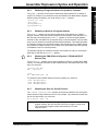
DEVELOPMENT SYSTEMS CUSTOMER CHANGE NOTIFICATION SERVICE
Microchip’s customer notification service helps keep customers current on Microchip
products. Subscribers will receive e-mail notification whenever there are changes,
updates, revisions or errata related to a specified product family or development tool of
interest.
To register, access the Microchip web site at www.microchip.com, click on Customer
Change Notification and follow the registration instructions.
The Development Systems product group categories are:
• Compilers – The latest information on Microchip C compilers and other language
tools. These include the MPLAB C18 and MPLAB C30 C compilers; MPASM™
and MPLAB ASM30 assemblers; MPLINK™ and MPLAB LINK30 object linkers;
and MPLIB™ and MPLAB LIB30 object librarians.
• Emulators – The latest information on Microchip in-circuit emulators.This
includes the MPLAB ICE 2000 and MPLAB ICE 4000.
• In-Circuit Debuggers – The latest information on the Microchip in-circuit
debugger, MPLAB ICD 2.
• MPLAB® IDE – The latest information on Microchip MPLAB IDE, the Windows®
Integrated Development Environment for development systems tools. This list is
focused on the MPLAB IDE, MPLAB IDE Project Manager, MPLAB Editor and
MPLAB SIM simulator, as well as general editing and debugging features.
• Programmers – The latest information on Microchip programmers. These include
the MPLAB PM3 and PRO MATE® II device programmers and the PICSTART®
Plus and PICkit™ 1development programmers.
DS51317E-page 6
© 2005 Microchip Technology Inc.
Preface
CUSTOMER SUPPORT
Users of Microchip products can receive assistance through several channels:
•
•
•
•
Distributor or Representative
Local Sales Office
Field Application Engineer (FAE)
Technical Support
Customers should contact their distributor, representative or field application engineer
(FAE) for support. Local sales offices are also available to help customers. A listing of
sales offices and locations is included in the back of this document.
Technical support is available through the web site at: http://support.microchip.com
© 2005 Microchip Technology Inc.
DS51317E-page 7
MPLAB® ASM30/LINK30 and Utilities User’s Guide
NOTES:
DS51317E-page 8
© 2005 Microchip Technology Inc.
Part 1 – MPLAB ASM30 Assembler
Chapter 1. Assembler Overview ................................................................................ 11
Chapter 2. MPLAB ASM30 Command Line Interface ............................................... 17
Chapter 3. Assembler Syntax .................................................................................... 31
Chapter 4. Assembler Expression Syntax and Operation ....................................... 39
Chapter 5. Assembler Symbols ................................................................................. 45
Chapter 6. Assembler Directives ............................................................................... 49
© 2005 Microchip Technology Inc.
DS51317E-page 9
MPLAB ASM30 Assembler
MPLAB® ASM30, MPLAB® LINK30
AND UTILITIES USER’S GUIDE
Part
1
MPLAB® ASM30/LINK30 and Utilities User’s Guide
NOTES:
DS51317E-page 10
© 2005 Microchip Technology Inc.
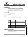
Chapter 1. Assembler Overview
1.1
INTRODUCTION
MPLAB ASM30 produces relocatable machine code from symbolic assembly language
for the dsPIC30F/33F DSC and PIC24X MCU family of devices. The assembler is a
Windows console application that provides a platform for developing assembly language code. The assembler is a port of the GNU assembler from the Free Software
Foundation.
1.2
HIGHLIGHTS
Topics covered in this chapter are:
• MPLAB ASM30 and Other Development Tools
• Feature Set
• Input/Output Files
1.3
MPLAB ASM30 AND OTHER DEVELOPMENT TOOLS
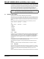
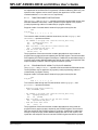
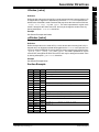
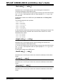
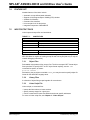
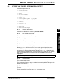
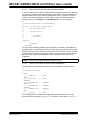
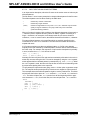
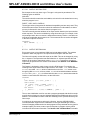
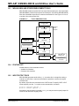
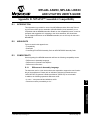
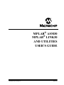
MPLAB ASM30 translates user assembly source files. In addition, the MPLAB C30 C
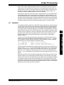
Compiler uses the assembler to produce its object file. The assembler generates relocatable object files that can then be put into an archive or linked with other relocatable
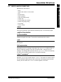
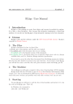
object files and archives to create an executable file. See Figure 1-1 for an overview of
the tools process flow.
FIGURE 1-1:
TOOLS PROCESS FLOW
C Source Files
(*.c)
C Compiler
Compiler
Driver
Program
Source Files (*.s)
Assembly Source
Files (*.s)
Archiver (Librarian)
Object File Libraries
(*.a)
Assembler
Object Files
(*.o)
Linker
Executable File
(*.exe)
MPLAB® IDE
Debug Tool
Command Line
Simulator
© 2005 Microchip Technology Inc.
DS51317E-page 11
MPLAB ASM30 Assembler
MPLAB® ASM30, MPLAB® LINK30
AND UTILITIES USER’S GUIDE
Part
1
MPLAB® ASM30/LINK30 and Utilities User’s Guide
1.4
FEATURE SET
Notable features of the assembler include:
•
•
•
•
•
•
•
•
1.5
Support for the entire 16-bit instruction set
Support for fixed-point and floating-point data
Support for COFF and ELF object formats
Available for Windows
Command Line Interface
Rich Directive Set
Flexible Macro Language
Integrated component of MPLAB® IDE
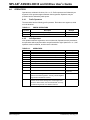
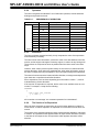
INPUT/OUTPUT FILES
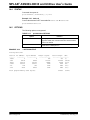
Standard assembler input and output files are listed below.
Extension
Description
Input
.s
source file
Output
.o
object file
.lst
listing file
Unlike the MPASM™ assembler (for use with PICmicro® MCUs), MPLAB ASM30 does
not generate error files, hex files, or symbol and debug files. MPLAB ASM30 is capable
of creating a listing file and a relocatable object file (that may or may not contain debugging information). MPLAB LINK30, the linker, is used with MPLAB ASM30 to produce
the final object files, map files and final executable file for debugging with MPLAB IDE
(see Figure 1-1).
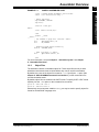
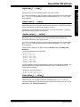
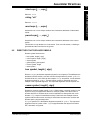
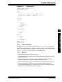
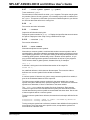
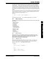
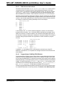
1.5.1
Source Files
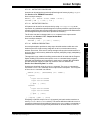
The assembler accepts, as input, a source file that consists of dsPIC30FXXXX
instructions, assembler directives and comments. A sample source file is shown in
Example 1-1.
Note:
DS51317E-page 12
Microchip Technology strongly suggests a .s extension for assembly
source files. This will enable you to easily use the C compiler driver without
having to specify the option to tell the driver that the file should be treated
as an assembly file. See the “MPLAB® C30 C Compiler User’s Guide”
(DS51284) for more details on the C compiler driver.
© 2005 Microchip Technology Inc.
Assembler Overview
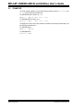
EXAMPLE 1-1:
Part
1
SAMPLE ASSEMBLER CODE
MPLAB ASM30 Assembler
.title " Sample dsPIC Assembler Source Code"
.sbttl " For illustration only."
; dsPIC registers
.equ CORCONL, CORCON
.equ PSV,2
.section .const,psv
hello:
.ascii "Hello world!\n\0"
.text
.global __reset
__reset:
; set PSVPAG to page that contains 'hello'
mov
#psvpage(hello),w0
mov
w0,PSVPAG
; enable Program Space Visibility
bset.b CORCONL,#PSV
; make a pointer to 'hello'
mov
#psvoffset(hello),w0
.end
For more information, see also Chapter 3. “Assembler Syntax” and Chapter
6. “Assembler Directives”.
1.5.2
Object Files
The assembler creates a relocatable object file. These object files do not yet have
addresses resolved and must be linked before they can be used for executables.
By default, the name of the object file created is a.out. Specify the -o option (See
Chapter 2. “MPLAB ASM30 Command Line Interface”) on the command line to
override the default name.
By default, object files are created in the COFF format. To specify COFF or ELF format
explicitly, use the -omf option on the command line, as shown:
pic30-as -omf=coff test.s
pic30-as -omf=elf test2.s
Alternatively, the environment variable PIC30_OMF may be used to specify object file
format for the dsPIC30F language tools.
© 2005 Microchip Technology Inc.
DS51317E-page 13
MPLAB® ASM30/LINK30 and Utilities User’s Guide
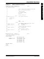
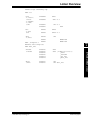
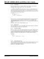
1.5.3
Listing Files
The assembler has the capability to produce listing files. These listing files are not
absolute listing files, and the addresses that appear in the listing are relative to the start
of sections.
By default, the listing file is displayed on standard output. Specify the -a=<file>
option (See Chapter 2. “MPLAB ASM30 Command Line Interface”) on the
command line to send the listing file to the specified file.
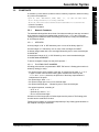
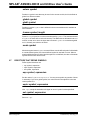
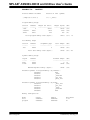
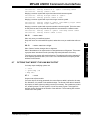
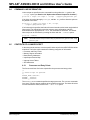
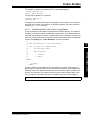
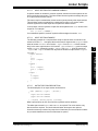
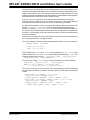
The listing files produced by the assembler are composed of the elements listed below.
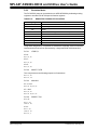
Example 1-2 shows a sample listing file.
• Header – contains the name of the assembler, the name of the file being
assembled, and a page number. This is not shown if the -an option is specified.
• Title Line – contains the title specified by the .title directive. This is not shown
if the -an option is specified.
• Subtitle – contains the subtitle specified by the .sbttl directive. This is not
shown if the -an option is specified.
• High-level source if the -ah option is given to the assembler. The format for
high-level source is:
<line #>:<filename>
**** <source>
For example:
1:hello.c
**** #include <stdio.h>
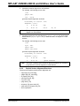
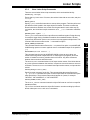
• Assembler source if the -al option is given to the assembler. The format for
assembler source is:
<line #> <addr> <encoded bytes> <source>
For example:
245 000004 00 0F 78
Note 1:
mov
w0,[w14]
Line numbers may be repeated.
2:
Addresses are relative to sections in this module and are not absolute.
3:
Instructions are encoded in “little endian” order.
• Symbol table if the -as option is given to the assembler. Both, a list of defined
and undefined symbols will be given.
The defined symbols will have the format:
DEFINED SYMBOLS
<filename>:<line #> <section>:<addr> <symbol>
For example:
DEFINED SYMBOLS
foo.s:229
.text:00000000 _main
The undefined symbols will have the format:
UNDEFINED SYMBOLS
<symbol>
For example:
UNDEFINED SYMBOLS
_printf
DS51317E-page 14
© 2005 Microchip Technology Inc.
Assembler Overview
EXAMPLE 1-2:
Part
1
SAMPLE ASSEMBLER LISTING FILE
MPLAB ASM30 Listing: example1.1.s
Sample dsPIC Assembler Source Code
For illustration only.
DEFINED SYMBOLS
*ABS*:00000000 fake
example1.1.s:10
.const:00000000 hello
example1.1.s:15
.text:00000000 __reset
.text:00000000 .text
.data:00000000 .data
.bss:00000000 .bss
.const:00000000 .const
page 2
UNDEFINED SYMBOLS
CORCON
PSVPAG
© 2005 Microchip Technology Inc.
DS51317E-page 15
MPLAB ASM30 Assembler
MPLAB ASM30 Listing: example1.1.s
page 1
Sample dsPIC Assembler Source Code
For illustration only.
1
2
.title " Sample dsPIC Assembler Source Code"
3
.sbttl " For illustration only."
4
5
; dsPIC registers
6
.equ CORCONL, CORCON
7
.equ PSV,2
8
9
.section .const,psv
10
hello:
11 0000 48 65 6C 6C
.ascii "Hello world!\n\0"
11
6F 20 77 6F
11
72 6C 64 21
11
0A 00
12
13
.text
14
.global __reset
15
__reset:
16
; set PSVPAG to page that contains 'hello'
17 000000 00 00 20
mov
#psvpage(hello),w0
18 000002 00 00 88
mov
w0,PSVPAG
19
20
; enable Program Space Visibility
21 000004 00 40 A8
bset.b CORCONL,#PSV
22
23
; make a pointer to 'hello'
24 000006 00 00 20
mov
#psvoffset(hello),w0
25
26
.end
MPLAB® ASM30/LINK30 and Utilities User’s Guide
NOTES:
DS51317E-page 16
© 2005 Microchip Technology Inc.
Chapter 2. MPLAB ASM30 Command Line Interface
2.1
INTRODUCTION
MPLAB ASM30 may be used on the command line interface as well as with MPLAB
IDE. For information on using the assembler with MPLAB IDE, please refer to “dsPIC®
Language Tools Getting Started” (DS70094).
2.2
HIGHLIGHTS
Topics covered in this chapter are:
•
•
•
•
•
2.3
Syntax
Options that Modify the Listing Output
Options that Control Informational Output
Options that Control Output File Creation
Other Options
SYNTAX
The MPLAB ASM30 command line may contain options and file names. Options may
appear in any order and may be before, after or between file names. The order of file
names determines the order of assembly.
pic30-as [options|sourcefiles]...
‘--’ (two hyphens) by itself names the standard input file explicitly, as one of the files
for the assembler to translate. Except for ‘--’, any command line argument that begins
with a hyphen (‘-’) is an option. Each option changes the behavior of the assembler,
but no option changes the way another option works.
Some options require exactly one file name to follow them. The file name may either
immediately follow the option’s letter or it may be the next command line argument. For
example, to specify an output file named test.o, either of the following options would
be acceptable:
• -o test.o
• -otest.o
Note:
© 2005 Microchip Technology Inc.
Command line options are case sensitive.
DS51317E-page 17
MPLAB ASM30 Assembler
MPLAB® ASM30, MPLAB® LINK30
AND UTILITIES USER’S GUIDE
Part
1
MPLAB® ASM30/LINK30 and Utilities User’s Guide
2.4
OPTIONS THAT MODIFY THE LISTING OUTPUT
The following options are used to control the listing output. For debugging and general
analysis of code operation, a listing file is helpful. Constructing one with useful
information is accomplished using the options in this section.
•
•
•
•
•
-a[suboption] [=file]
--listing-lhs-width #
--listing-lhs-width2 #
--listing-rhs-width #
--listing-cont-lines #
2.4.1
-a[suboption] [=file]
The -a option enables listing output. The -a option supports the following sub options
to further control what is included in the assembly listing:
-ac
Omit false conditionals
-ad
Omit debugging directives
-ah
Include high-level source
-ai
Include section information
-al
Include assembly
-am
Include macro expansions
-an
Omit forms processing
-as
Include symbols
-a=file
Output listing to specified file (must be in current directory).
If no sub-options are specified, the default sub-options used are hls; the -a option by
itself requests high-level, assembly, and symbolic listing. You can use other letters to
select specific options for the listing output.
The letters after the -a may be combined into one option. So for example instead of
specifying -al -an on the command line, you could specify -aln.
DS51317E-page 18
© 2005 Microchip Technology Inc.
MPLAB ASM30 Command Line Interface
2.4.1.1
Part
1
-ac
EXAMPLE 2-1:
LISTING FILE GENERATED WITH -al COMMAND LINE
OPTION
MPLAB ASM30 Listing:
1
2
3
4
5
6
7
8
9
10
11
12 0000 02 00 00 00
13
14
15
16 0004 04 00 00 00
17
18
19
20
21
22
23
24
25
26 0008 07 00 00 00
27
28
29
30
31
32
© 2005 Microchip Technology Inc.
example2.1.s
page 1
.data
.if 0
.if 1
.endif
.long 0
.if 0
.long 0
.endif
.else
.if 1
.endif
.long 2
.if 0
.long 3
.else
.long 4
.endif
.endif
.if 0
.long 5
.elseif 1
.if 0
.long 6
.elseif 1
.long 7
.endif
.elseif 1
.long 8
.else
.long 9
.endif
DS51317E-page 19
MPLAB ASM30 Assembler
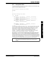
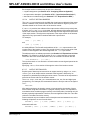
-ac omits false conditionals from a listing. Any lines that are not assembled because
of a false .if or .ifdef (or the .else of a true .if or .ifdef) will be omitted from
the listing. Example 2-1 shows a listing where the -ac option was not used.
Example 2-2 shows a listing for the same source where the -ac option was used.
MPLAB® ASM30/LINK30 and Utilities User’s Guide
EXAMPLE 2-2:
LISTING FILE GENERATED WITH -alc COMMAND LINE
OPTION
MPLAB ASM30 Listing:
1
2
9
10
11
12 0000 02 00 00 00
13
15
16 0004 04 00 00 00
17
18
19
20
22
23
25
26 0008 07 00 00 00
27
28
30
32
Note:
DS51317E-page 20
example2.2.s
page 1
.data
.if 0
.else
.if 1
.endif
.long 2
.if 0
.else
.long 4
.endif
.endif
.if 0
.elseif 1
.if 0
.elseif 1
.long 7
.endif
.elseif 1
.else
.endif
Some lines omitted due to -ac option, i.e., lines 3-8, 14, 21, 24, 29 and 31.
© 2005 Microchip Technology Inc.
MPLAB ASM30 Command Line Interface
2.4.1.2
Part
1
-ad
EXAMPLE 2-3:
LISTING FILE GENERATED WITH -alhd COMMAND LINE
OPTION
MPLAB ASM30 Listing:
example2.3.s
1
2
3
9
10
1:example2.3.c ****
2:example2.3.c ****
3:example2.3.c ****
4:example2.3.c ****
5:example2.3.c ****
16
17 000000 00 00 FA
18
6:example2.3.c ****
20 000002 51 00 20
21 000004 40 00 20
22 000006 00 00 02
22
00 00 00
7:example2.3.c ****
29
30 00000a 00 80 FA
31 00000c 00 00 06
32
37
38
© 2005 Microchip Technology Inc.
page 1
.file "example2.3.c"
.text
.align 2
.global _main ; export
_main:
extern int ADD (int, int);
int
main(void)
{
.set
lnk
___PA___,1
#0
return ADD(4, 5);
mov
#5,w1
mov
#4,w0
call
_ADD
}
ulnk
return
.set
___PA___,0
.end
DS51317E-page 21
MPLAB ASM30 Assembler
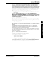
-ad omits debugging directives from the listing. This is useful if a compiler that
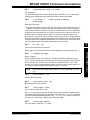
was given a debugging option generated the assembly source code. The compilergenerated debugging directives will not clutter the listing. Example 2-3 shows a listing
using both the d and h sub-options. Compared to using the h sub-option alone (see
next section), the listing is much cleaner.
MPLAB® ASM30/LINK30 and Utilities User’s Guide
2.4.1.3
-ah
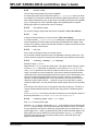
-ah requests a high-level language listing. High-level listings require that the assembly
source code was generated by a compiler, a debugging option like -g was given to the
compiler, and that assembly listings (-al) also be requested. -al requests an output
program assembly listing. Example 2-4 shows a listing that was generated using the
-alh command line option.
EXAMPLE 2-4:
LISTING FILE GENERATED WITH -alh COMMAND LINE
OPTION
MPLAB ASM30 Listing:
example2.4.s
1
2
3
4
5
6
7
8
9
10
11
12
13
1:example2.4.c ****
2:example2.4.c ****
3:example2.4.c ****
4:example2.4.c ****
5:example2.4.c ****
14
15
16
17 000000 00 00 FA
18
6:example2.4.c ****
19
20 000002 51 00 20
21 000004 40 00 20
22 000006 00 00 02
22
00 00 00
7:example2.4.c ****
23
24
25
26
27
28
29
30 00000a 00 80 FA
31 00000c 00 00 06
32
33
34
35
36
37
38
DS51317E-page 22
page 1
.file "example2.4.c"
.text
.align 2
.def
_main
.val
_main
.scl
2
.type
044
.endef
.global _main ; export
_main:
.def
.bf
.val
.
.scl
101
extern int ADD (int, int);
int
main(void)
{
.line
.endef
.set
lnk
5
___PA___,1
#0
return ADD(4, 5);
.ln
6
mov
#5,w1
mov
#4,w0
call
_ADD
}
.ln
.def
.val
.scl
.line
.endef
ulnk
return
.set
.def
.val
.scl
.endef
7
.ef
.
101
7
___PA___,0
_main
.
-1
.end
© 2005 Microchip Technology Inc.
MPLAB ASM30 Command Line Interface
2.4.1.4
Part
1
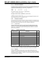
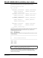
-ai
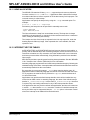
EXAMPLE 2-5:
LISTING FILE GENERATED WITH -ai COMMAND LINE
OPTION
SECTION INFORMATION:
Section
------.text
Length (PC units)
----------------0x16
Length (bytes) (dec)
-------------------0x21 (33)
TOTAL PROGRAM MEMORY USED (bytes):
Section
------.data
.bss
0x21
Length (bytes) (dec)
-------------------0 (0)
0 (0)
TOTAL DATA MEMORY USED (bytes):
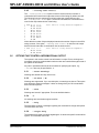
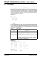
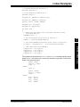
2.4.1.5
(33)
0
(0)
-al
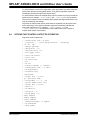
-al requests an assembly listing. This sub-option may be used with other sub-options.
See the other examples in this section.
2.4.1.6
-am
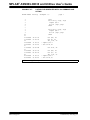
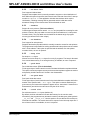
-am expands macros in a listing. Example 2-6 shows a listing where the -am option
was not used. Example 2-7 shows a listing for the same source where the -am option
was used.
EXAMPLE 2-6:
LISTING FILE GENERATED WITH -al COMMAND LINE
OPTION
MPLAB ASM30 Listing:
1
2
3
4
5
6
7
8
9
10
11
12
13
14
14
15
16
17
18
19
20
20
example2.5.s
page 1
.text
.macro div_s reg1, reg2
repeat #18-1
div.sw \reg1,\reg2
.endm
.macro div_u reg1, reg2
repeat #18-1
div.uw \reg1,\reg2
.endm
000000
000002
000004
40
52
11
02
20
20
09
D8
mov #20, w0
mov #5, w2
div_u w0, w2
000008
00 02 BE
mov.d w0, w4
00000a
00000c
00000e
40
B3
11
03
mov #20, w0
mov #-5, w3
div_s w0, w3
© 2005 Microchip Technology Inc.
01
00
00
80
01
FF
00
00
20
2F
09
D8
DS51317E-page 23
MPLAB ASM30 Assembler
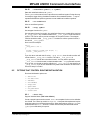
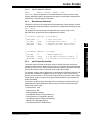
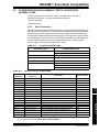
-ai displays information on each of the code and data sections. This information contains details on the size of each of the sections and then a total usage of program and
data memory. Example 2-5 shows a listing where the -ai option was used.
MPLAB® ASM30/LINK30 and Utilities User’s Guide
EXAMPLE 2-7:
LISTING FILE GENERATED WITH -alm COMMAND LINE
OPTION
MPLAB ASM30 Listing:
1
2
3
4
5
6
7
8
9
10
11
12
13
14
14
14
15
16
17
18
19
20
20
20
page 1
.text
.macro div_s reg1, reg2
repeat #18-1
div.sw \reg1,\reg2
.endm
.macro div_u reg1, reg2
repeat #18-1
div.uw \reg1,\reg2
.endm
000000
000002
40 01 20
52 00 20
000004
000006
11 00 09
02 80 D8
mov #20, w0
mov #5, w2
div_u w0, w2
> repeat #18-1
> div.uw w0,w2
000008
00 02 BE
mov.d w0, w4
00000a
00000c
40 01 20
B3 FF 2F
00000e
000010
11 00 09
03 00 D8
mov #20, w0
mov #-5, w3
div_s w0, w3
> repeat #18-1
> div.sw w0,w3
Note:
DS51317E-page 24
example2.6.s
> signifies expanded macro instructions.
© 2005 Microchip Technology Inc.
MPLAB ASM30 Command Line Interface
2.4.1.7
Part
1
-an
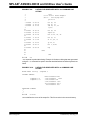
EXAMPLE 2-8:
LISTING FILE GENERATED WITH -al COMMAND LINE
OPTION
MPLAB ASM30 Listing:
User's Guide Example
Listing Options
1
2
3
4
5
6 000000 50 00 20
7 000002 61 00 20
MPLAB ASM30 Listing:
User's Guide Example
Listing Options
8 000004 01 01 40
9
MPLAB ASM30 Listing:
User's Guide Example
Listing Options
10
11 000006 24 00 20
12 000008 03 00 09
13 00000a 04 22 B8
14
15 00000c 16 00 20
16 00000e 64 33 DD
MPLAB ASM30 Listing:
User's Guide Example
Listing Options
17
18 000010 06 20 E1
19 000012 00 00 32
20
21 000014 00 00 00
22
23
MPLAB ASM30 Listing:
User's Guide Example
Listing Options
24
25
© 2005 Microchip Technology Inc.
example2.7.s
page 1
.text
.title "User's Guide Example"
.sbttl " Listing Options"
.psize 10
mov #5, w0
mov #6, w1
example2.7.s
page 2
add w0, w1, w2
.eject
example2.7.s
page 3
mov #2, w4
repeat #3
mul.uu w4, w4, w4
mov #1, w6
sl w6, #4, w6
example2.7.s
page 4
cp w4, w6
bra z, done
nop
done:
example2.7.s
page 5
.end
DS51317E-page 25
MPLAB ASM30 Assembler
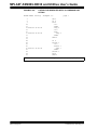
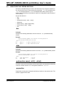
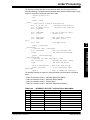
-an turns off all forms processing that would be performed by the listing directives
.psize, .eject, .title and .sbttl. Example 2-8 shows a listing where the -an
option was not used. Example 2-9 shows a listing for the same source where the -an
option was used.
MPLAB® ASM30/LINK30 and Utilities User’s Guide
EXAMPLE 2-9:
1
2
3
4
5
6
7
8
9
10
11
12
13
14
15
16
17
18
19
20
21
22
23
24
25
LISTING FILE GENERATED WITH -aln COMMAND LINE
OPTION
.text
.title "User's Guide Example"
.sbttl " Listing Options"
.psize 10
000000
000002
000004
50 00 20
61 00 20
01 01 40
mov #5, w0
mov #6, w1
add w0, w1, w2
.eject
000006
000008
00000a
24 00 20
03 00 09
04 22 B8
mov #2, w4
repeat #3
mul.uu w4, w4, w4
00000c
00000e
16 00 20
64 33 DD
mov #1, w6
sl w6, #4, w6
000010
000012
06 20 E1
00 00 32
cp w4, w6
bra z, done
000014
00 00 00
nop
2.4.1.8
done:
.end
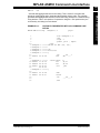
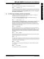
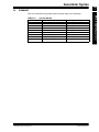
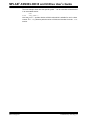
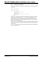
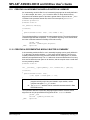
-as
-as requests a symbol table listing. Example 2-10 shows a listing that was generated
using the -as command line option. Note that both defined and undefined symbols are
listed.
EXAMPLE 2-10:
LISTING FILE GENERATED WITH -as COMMAND LINE
OPTION
MPLAB ASM30 Listing:
sample2b.s
DEFINED SYMBOLS
sample2b.s:4
sample2b.s:13
*ABS*:00000000
.text:00000000
.text:0000001c
.text:00000000
.data:00000000
.bss:00000000
fake
__reset
L2
.text
.data
.bss
UNDEFINED SYMBOLS
_i
_j
2.4.1.9
-a=file
=file defines the name of the output file. This file must be in the current directory.
DS51317E-page 26
© 2005 Microchip Technology Inc.
MPLAB ASM30 Command Line Interface
2.4.2
Part
1
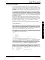
--listing-lhs-width #
6 000000
50 00 20
mov #5, w0
If the option --listing-lhs-width 2 is used, then the same line will appear as
follows in the listing:
6 000000
6
2.4.3
mov #5, w0
50 00
20
--listing-lhs-width2 #
The --listing-lhs-width2 option is used to set the width of the continuation lines
of the output data column of the listing file. By default, this is set to 3 for program
memory and 4 for data memory. If the specified width is smaller than the first line, this
option is ignored. The following lines are extracted from a listing. The output data
column is bolded.
2 0000 50 6C 65
2
73 65 20
2
61 79 20
2
6E 73 69
2
65 2E
61
70
69
64
.ascii "Please pay inside."
If the option --listing-lhs-width2 7 is used, then the same line will appear as
follows in the listing:
2 0000 50 6C 65 61
.ascii "Please pay inside."
2
73 65 20 70 61 79 20
2
69 6E 73 69 64 65 2E
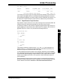
2.4.4
--listing-rhs-width #
The --listing-rhs-width option is used to set the maximum width in characters
of the lines from the source file. By default, this is set to 100. The following lines are
extracted from a listing that was created without using the --listing-rhs-width
option. The text in bold are the lines from the source file.
2 0000 54 68 69 73 .ascii "This line is long."
2
20 6C 69 6E
2
65 20 69 73
2
20 6C 6F 6E
2
67 65 72 20
If the option --listing-rhs-width 20 is used, then the same line will appear as
follows in the listing:
2 0000 54 68 69 73 .ascii "This line i
2
20 6C 69 6E
2
65 20 69 73
2
20 6C 6F 6E
2
67 65 72 20
The line is truncated (not wrapped) in the listing, but the data is still there.
© 2005 Microchip Technology Inc.
DS51317E-page 27
MPLAB ASM30 Assembler
The --listing-lhs-width option is used to set the width of the output data column
of the listing file. By default, this is set to 3 for program memory and 4 for data memory.
The following line is extracted from a listing. The output data column is in bold text.
MPLAB® ASM30/LINK30 and Utilities User’s Guide
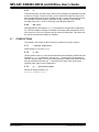
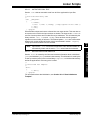
2.4.5
--listing-cont-lines #
The --listing-cont-lines option is used to set the maximum number of
continuation lines used for the output data column of the listing. By default, this is 8.
The following lines are extracted from a listing that was created without using
the--listing-cont-lines option. The text in bold shows the continuation lines
used for the output data column of the listing.
2 0000 54 68 69 73
2
20 69 73 20
2
61 20 6C 6F
2
6E 67 20 63
2
68 61 72 61
2
63 74 65 72
2
20 73 65 71
2
75 65 6E 63
2
65 2E
.ascii "This is a long character sequence."
Notice that the number of bytes displayed matches the number of bytes in the ASCII
string; however, if the option --listing-cont-lines 2 is used, then the output
data will be truncated after 2 continuation lines as shown below.
2 0000 54 68 69 73
2
20 69 73 20
2
61 20 6C 6F
2.5
.ascii "This is a long character sequence."
OPTIONS THAT CONTROL INFORMATIONAL OUTPUT
The options in this section control how information is output. Errors, warnings and
messages concerning code translation and execution are controlled through several of
the options in this section.
Any item in parenthesis shows the short method of specifying the option, e.g.,
--no-warn also may be specified as -W.
2.5.1
--fatal-warnings
Warnings are treated as if they were errors.
2.5.2
--no-warn (-W)
Warnings are suppressed. If you use this option, no warnings are issued. This option
only affects the warning messages. It does not change how your file is assembled.
Errors are still reported.
2.5.3
--warn
Warnings are issued, if appropriate. This is the default behavior.
2.5.4
-J
No warnings are issued about signed overflow.
2.5.5
--help
The assembler will show a message regarding the command line usage and options.
The assembler then exits.
2.5.6
--target-help
The assembler will show a message regarding the 16-bit device specific command line
options. The assembler then exits.
DS51317E-page 28
© 2005 Microchip Technology Inc.
MPLAB ASM30 Command Line Interface
2.5.7
Part
1
--version
The assembler version number is displayed. The assembler then exits.
--verbose (-v)
The assembler version number is displayed. The assembler does not exit. If this is the
only command line option used, then the assembler will print out the version and wait
for entry of the assembly source through standard input. Use <CTRL>-D to send an
EOF character to end assembly.
2.6
OPTIONS THAT CONTROL OUTPUT FILE CREATION
The options in this section control how the output file is created. For example, to
change the name of the output object file, use -o.
Any item in parenthesis shows the short method of specifying the option, e.g.,
--keep-locals may be specified as -L also.
2.6.1
--keep-locals (-L)
Keep local symbols, i.e., labels beginning with .L (upper case only). Normally you do
not see such labels when debugging, because they are intended for the use of
programs (like compilers) that compose assembler programs. Normally both the
assembler and linker discard such symbols. This option tells the assembler to retain
those symbols in the object files.
2.6.2
-o objfile
Name the object file output objfile. In the absence of errors, there is always one
object file output when you run the assembler. By default, it has the name a.out. Use
this option (which takes exactly one filename) to give the object file a different name.
Whatever the object file is called, the assembler overwrites any existing file with the
same name.
2.6.3
-omf = format
Use this option to specify the object file format. Valid format names are COFF and ELF.
Object file format names are not case sensitive.
2.6.4
-R
This option tells the assembler to write the object file as if all data-section data lives in
the text section. The data section part of your object file is zero bytes long because all
its bytes are located in the text section.
2.6.5
--relax
Turn relaxation on. Convert absolute calls and gotos to relative calls and branches
when possible.
2.6.6
--no-relax
Turn relaxation off. This is the default behavior.
© 2005 Microchip Technology Inc.
DS51317E-page 29
MPLAB ASM30 Assembler
2.5.8
MPLAB® ASM30/LINK30 and Utilities User’s Guide
2.6.7
-Z
Generate object file even after errors. After an error message, the assembler normally
produces no output. If for some reason, you are interested in object file output even
after the assembler gives an error message, use the -Z option. If there are any errors,
the assembler continues anyway, and writes an object file after a final warning
message of the form “n errors, m warnings, generating bad object file”.
2.6.8
-MD file
Write dependency information to file. The assembler can generate a dependency
file. This file consists of a single rule suitable for describing the dependencies of the
main source file. The rule is written to the file named in its argument. This feature can
be used in the automatic updating of makefiles.
2.7
OTHER OPTIONS
The options in this section perform functions not defined in previous sections.
2.7.1
--defsym sym=value
Define symbol sym to given value.
2.7.2
-I dir
Use this option to add dir to the list of directories that the assembler searches for files
specified in .include directives. You may use -I as many times as necessary to
include a variety of paths. The current working directory is always searched first; after
that, the assembler searches any -I directories in the same order as they were
specified (left to right) on the command line.
2.7.3
-p, --processor=PROC
Specify the target processor, e.g.:
pic30-as -p30F2010 file.s
DS51317E-page 30
© 2005 Microchip Technology Inc.
Chapter 3. Assembler Syntax
3.1
INTRODUCTION
Syntax for MPLAB ASM30 source code is defined here.
3.2
HIGHLIGHTS
Topics covered in this chapter are:
•
•
•
•
3.3
Internal Preprocessor
Source Code Format
Constants
Summary
INTERNAL PREPROCESSOR
The assembler has an internal preprocessor. The internal processor:
1. Adjusts and removes extra white space. It leaves one space or tab before the
keywords on a line, and turns any other white space on the line into a single
space.
2. Removes all comments, replacing them with a single space, or an appropriate
number of new lines.
3. Converts character constants into the appropriate numeric value.
Note:
If you have a single character (e.g., ‘b’) in your source code, this will be
changed to the appropriate numeric value. If you have a syntax error that
occurs at the single character, the assembler will not display ‘b’, but instead
display the first digit of the decimal equivalent.
For example, if you had .global mybuf, ‘b’ in your source code, the error
message would say “Error: Rest of line ignored. First ignored character is ‘9’.”
Notice the error message says ‘9’. This is because the ‘b’ was converted to its
decimal equivalent 98. The assembler is actually parsing .global mybuf,98
The internal processor does not do:
1. macro preprocessing
2. include file handling
3. anything else you may get from your C compiler’s preprocessor
You can do include file preprocessing with the .include directive (See Chapter
6. “Assembler Directives”.) You can use the C compiler driver to get other C
preprocessing style preprocessing by giving the input file a .S suffix (See the “MPLAB®
C30 C Compiler User’s Guide” (DS51284) for more information.)
© 2005 Microchip Technology Inc.
DS51317E-page 31
MPLAB ASM30 Assembler
MPLAB® ASM30, MPLAB® LINK30
AND UTILITIES USER’S GUIDE
Part
1
MPLAB® ASM30/LINK30 and Utilities User’s Guide
If the first line of an input file is #NO_APP or if you use the -f option, white space and
comments are not removed from the input file. Within an input file, you can ask for white
space and comment removal in certain portions by putting a line that says #APP before
the text that may contain white space or comments, and putting a line that says
#NO_APP after this text. This feature is mainly intended to support assembly
statements in compilers whose output is otherwise free of comments and white space.
Note:
3.4
Excess white space, comments and character constants cannot be used
in the portions of the input text that are not preprocessed.
SOURCE CODE FORMAT
Assembly source code consists of statements and white spaces.
White space is one or more spaces or tabs. White space is used to separate pieces of
a source line. White space should be used to make your code easier for people to read.
Unless within character constants, any white space means the same as exactly one
space.
Each statement has the following general format and is followed by a new line.
[label:]
[mnemonic
[operands] ]
[; comment]
[directive
[arguments] ]
[; comment]
OR
[label:]
•
•
•
•
•
•
Label
Mnemonic
Directive
Operands
Arguments
Comments
3.4.1
Label
A label is one or more characters chosen from the set of all letters, digits and the two
characters underline (_) and period (.). Labels may not begin with a decimal digit,
except for the special case of a local symbol. (See Section 5.5 “Local Symbols” for
more information.) Case is significant. There is no length limit; all characters are
significant.
Label definitions must be immediately followed by a colon. A space, tab, end of line or
an assembler mnemonic or directive may follow the colon.
Label definitions may appear on a line by themselves and will reference the next
address.
The value of a label after linking is the absolute address of a location in memory.
3.4.2
Mnemonic
Mnemonics tell the assembler what machine instructions to assemble. For example,
addition (ADD), branches (BRA) or moves (MOV). Unlike labels that you create yourself,
mnemonics are provided by the assembly language. Mnemonics are not case
sensitive.
See the “dsPIC30F/33F Programmer’s Reference Manual” (DS70157) for more details.
DS51317E-page 32
© 2005 Microchip Technology Inc.
Assembler Syntax
3.4.3
Part
1
Directive
3.4.4
Operands
Each machine instruction takes from 0 up to 8 operands. (See the “dsPIC30F/33F Programmer’s Reference Manual” (DS70157). These operands give information to the
instruction on the data that should be used and the storage location for the instruction.
Operands must be separated from mnemonics by one or more spaces or tabs.
Commas should separate multiple operands. If commas do not separate operands, a
warning will be displayed and the assembler will take its best guess on the separation
of the operands. Operands consist of literals, file registers condition codes, destination
select and accumulator select.
3.4.4.1
LITERALS
Literal values are distinguished with a preceding pound sign (‘#’). Literal values can be
hexadecimal, octal, binary or decimal format. Hexadecimal numbers are distinguished
by a leading 0x. Octal numbers are distinguished by a leading 0. Binary numbers are
distinguished by a leading B. Decimal numbers require no special leading or trailing
character.
Examples:
#0xe, #016, #0b1110 and #14 all represents the literal value 14.
#-5 represents the literal value -5.
#symbol represents the value of symbol.
3.4.4.2
FILE REGISTERS
File registers represent on-chip general purpose and special function registers. File
registers are distinguished from literal values because they do not have the preceding
pound sign.
Each of the following examples tells the processor to move the data located in the file
register whose address is 14 to w0:
mov 0xE, w0
mov 016, w0
mov 14, w0
.equ symbol, 14
mov symbol, w0
3.4.4.3
REGISTERS
The following register names are built into the assembler:
w0, w1, w2, w3, w4, w5, w6, w7, w8, w9, w10, w11, w12, w13, w14, w15, W0, W1, W2,
W3, W4, W5, W6, W7, W8, W9, W10, W11, W12, W13, W14, W15.
3.4.4.4
CONDITION CODES
Condition codes are used with BRA instructions. See the “dsPIC30F/33F Programmer’s
Reference Manual” (DS70157) for more details.
bra C, label
© 2005 Microchip Technology Inc.
DS51317E-page 33
MPLAB ASM30 Assembler
Assembler directives are commands that appear in the source code but are not
translated directly into machine code. Directives are used to control the assembler; its
input, output and data allocation. The first character of a directive is a period (.). More
details are provided in Chapter 6. “Assembler Directives” on the available directives.
MPLAB® ASM30/LINK30 and Utilities User’s Guide
3.4.4.5
DESTINATION SELECT
The PIC18CXXX-compatible instructions accept WREG as an optional argument to
specify whether the result should be placed into WREG (W0) or into the file register. See
the “dsPIC30F/33F Programmer’s Reference Manual” (DS70157) for more details.
add sym, WREG
3.4.4.6
ACCUMULATOR SELECT
The DSP instructions take an accumulator select operand (A or B) to specify which
accumulator to use.
ADD A
3.4.5
Arguments
Each directive takes from 0 up to 3 arguments. These arguments give additional
information to the directive on how it should carry out the command. Arguments must
be separated from directives by one or more spaces or tabs. Commas must separate
multiple arguments. More details are provided in Chapter 6. “Assembler Directives”
on the available directives.
3.4.6
Comments
Comments can be represented in the assembler in one of two ways described below.
3.4.6.1
SINGLE LINE COMMENT
This type of comment extends from the comment character to the end of the line. For
a single line comment, use a semicolon (‘;’).
Example:
mov w0, w1;The rest of this line is a comment.
3.4.6.2
MULTILINE COMMENT
This type of comment can span multiple lines. For a multi-line comment, use
/* ... */. These comments cannot be nested.
Example:
/* All
of these
lines
are
comments */
DS51317E-page 34
© 2005 Microchip Technology Inc.
Assembler Syntax
3.5
Part
1
CONSTANTS
.byte 74, 0112, 0b01001010, 0x4A, 0x4a, ’J’, ’\J’;All the same value
.ascii "Ring the bell\7";A string constant
.float 0f-31415926535897932384626433832795028841971.693993751E-40
• Numeric Constants
• Character Constants
3.5.1
Numeric Constants
The assembler distinguishes three kinds of numbers according to how they are stored
in the machine. Integers are numbers that would fit into a long in the C language.
Floating-point numbers are IEEE 754 floating-point numbers. Fixed-point numbers are
Q-15 fixed-point format.
3.5.1.1
INTEGERS
A binary integer is ‘0b’ or ‘0B’ followed by zero or more of the binary digits ‘01’.
An octal integer is ‘0’ followed by zero or more of the octal digits ‘01234567’.
A decimal integer starts with a non-zero digit followed by zero or more decimal digits
‘0123456789’.
A hexadecimal integer is ‘0x’ or ‘0X’ followed by one or more hexadecimal digits
‘0123456789abcdefABCDEF’.
To denote a negative integer, use the prefix operator ‘-’.
3.5.1.2
FLOATING-POINT NUMBERS
A floating-point number is represented in IEEE 754 format. A floating-point number is
written by writing (in order):
• An optional prefix, which consists of the digit ‘0’, followed by the letter ‘e’, ‘f’ or ‘d’
in upper or lower case. Because floating point constants are used only with
.float and .double directives, the precision of the binary representation is
independent of the prefix.
• An optional sign: either ‘+’ or ‘-’.
• An optional integer part: zero or more decimal digits.
• An optional fractional part: ‘.’ followed by zero or more decimal digits.
• An optional exponent, consisting of:
- An ‘E’ or ‘e’.
- Optional sign: either ‘+’ or ‘-’.
- One or more decimal digits.
At least one of the integer part or fractional part must be present. The floating-point
number has the usual base-10 value.
Floating-point numbers are computed independently of any floating-point hardware in
the computer running the assembler.
© 2005 Microchip Technology Inc.
DS51317E-page 35
MPLAB ASM30 Assembler
A constant is a value written so that its value is known by inspection, without knowing
any context. Examples are:
MPLAB® ASM30/LINK30 and Utilities User’s Guide
3.5.1.3
FIXED-POINT NUMBERS
A fixed-point number is represented in Q-15 format. This means that 15 bits are used
to represent the fractional portion of the number. The most significant bit is the sign bit,
followed by an implied binary point, and 15 bits of magnitude, i.e.:
bit no.
15
.
14
13
12
...
1
value
±20 .
2-1
2-2
2-3
...
2-14 2-15
0
The smallest number in this format is -1, represented by:
0x8000 (1.000 0000 0000 0000)
the largest number is nearly 1 (.99996948), represented by:
0x7FFF (0.111 1111 1111 1111)
A fixed-point number is written in the same format as a floating-point number, but its
value is constrained to be in the range [-1.0, 1.0).
3.5.2
Character Constants
There are two kinds of character constants. A character stands for one character in one
byte and its value may be used in numeric expressions. A string can contain potentially
many bytes and their values may not be used in arithmetic expressions.
3.5.2.1
CHARACTERS
A single character may be written as a single quote immediately followed by that
character, or as a single quote immediately followed by that character and another
single quote. The assembler accepts the following escape characters to represent
special control characters:
TABLE 3-1:
ESCAPE CHARACTERS
Escape Character
Hex
Value
Description
\a
Bell (alert) character
07
\b
Backspace character
08
\f
Form-feed character
0C
\n
New-line character
0A
\r
Carriage return character
0D
\t
Horizontal tab character
09
\v
Vertical tab character
0B
\\
Backslash
5C
\?
Question mark character
3F
\"
Double quote character
22
\digit digit digit Octal character code. The numeric code is 3 octal digits.
\x hex-digits
Hex character code. All trailing hex digits are combined.
Either upper or lower case x works.
The value of a character constant in a numeric expression is the machine’s byte-wide
code for that character. The assembler assumes your character code is ASCII.
3.5.2.2
STRINGS
A string is written between double quotes. It may contain double quotes or null
characters. The way to get special characters into a string is to escape the characters,
preceding them with a backslash ‘\’ character. The same escape sequences that apply
to strings also apply to characters.
DS51317E-page 36
© 2005 Microchip Technology Inc.
Assembler Syntax
3.6
Part
1
SUMMARY
Table 3-2 summarizes the general syntax rules that apply to the assembler:
SYNTAX RULES
Character
Character Description
Syntax Usage
.
period
begins a directive or label
;
semicolon
begin single-line comment
/*
slash, asterisk
begin multiple-line comment
*/
asterisk, slash
end multiple-line comment
:
colon
end a label definition
#
pound
begin a literal value
’c’
character in single quotes
specifies single character value
"string"
character string in double quotes
specifies a character string
© 2005 Microchip Technology Inc.
DS51317E-page 37
MPLAB ASM30 Assembler
TABLE 3-2:
MPLAB® ASM30/LINK30 and Utilities User’s Guide
NOTES:
DS51317E-page 38
© 2005 Microchip Technology Inc.
Chapter 4. Assembler Expression Syntax and Operation
4.1
INTRODUCTION
Expression syntax and operation for MPLAB ASM30 is discussed here.
4.2
HIGHLIGHTS
Topics covered in this chapter are:
• Expressions
• Operators
• Special Operators
4.3
EXPRESSIONS
An expression specifies an address or numeric value. White space may precede and/or
follow an expression. The result of an expression must be an absolute number, or else
an offset into a particular section. If an expression is not absolute, and there is not
enough information when the assembler sees the expression to know its section, the
assembler terminates with an error message in this situation.
4.3.1
Empty Expressions
An empty expression has no value: it is just white space or null. Wherever an absolute
expression is required, you may omit the expression, and the assembler assumes a
value of (absolute) 0.
4.3.2
Integer Expressions
An integer expression is one or more arguments delimited by operators. Arguments are
symbols, numbers or sub expressions. Sub expressions are a left parenthesis ‘(’
followed by an integer expression, followed by a right parenthesis ‘)’; or a prefix
operator followed by an argument.
Integer expressions involving symbols in program memory are evaluated in Program
Counter (PC) units. On the 16-bit device, the Program Counter increments by 2 for
each instruction word. For example, to branch to the next instruction after label L, specify L+2 as the destination.
Example:
bra L+2
© 2005 Microchip Technology Inc.
DS51317E-page 39
MPLAB ASM30 Assembler
MPLAB® ASM30, MPLAB® LINK30
AND UTILITIES USER’S GUIDE
Part
1
MPLAB® ASM30/LINK30 and Utilities User’s Guide
4.4
OPERATORS
Operators are arithmetic functions, like + or %. Prefix operators are followed by an
argument. Infix operators appear between their arguments. Operators may be
preceded and/or followed by white space.
4.4.1
Prefix Operators
The assembler has the following prefix operators. Each takes one argument, which
must be absolute.
TABLE 4-1:
PREFIX OPERATORS
Operator
Description
Example
-
Negation. Two’s complement negation.
-1
~
Bit-wise not. One’s complement.
~flags
4.4.2
Infix Operators
Infix operators take two arguments, one on either side. Operators have a precedence,
but operations with equal precedence are performed left to right. Apart from + or –, both
operators must be absolute, and the result is absolute.
TABLE 4-2:
OPERATORS
Operator
DS51317E-page 40
Description
Example
*
Multiplication
5 * 4 (=20)
/
Division. Truncation is the same as the C operator ‘/’.
23 / 4 (=5)
%
Remainder
30 % 4 (=2)
<<
Shift Left. Same as the C operator ‘<<’
2 << 1 (=4)
>>
Shift Right. Same as the C operator ‘>>’
2 >> 1 (=1)
|
Bit-wise Inclusive Or
2 | 4 (=6)
&
Bit-wise And
4 & 6 (=4)
^
Bit-wise Exclusive Or
4 ^ 6 (=2)
!
Bit-wise Or Not
0x1010 ! 0x5050
(=0xBFBF)
+
Addition. If either argument is absolute, the result has the 4 + 10 (=14)
section of the other argument. You may not add together
arguments from different sections.
-
Subtraction. If the right argument is absolute, the result
has the section of the left argument. If both arguments
are in the same section, the result is absolute. You may
not subtract arguments from different sections.
14 - 4 (=10)
© 2005 Microchip Technology Inc.
Assembler Expression Syntax and Operation
4.5
Part
1
SPECIAL OPERATORS
The assembler provides a set of special operators for the following:
Accessing Data in Program Memory
Obtaining a Program Address of a Symbol or Constant
Obtaining a Handle to a Program Address
Obtaining the Size of a Specific Section
Obtaining the Starting Address of a Specific Section
TABLE 4-3:
SPECIAL OPERATORS
Operators
Description
Support
tblpage(name)
Get page for table read/write operations
All
tbloffset(name)
Get pointer for table read/write operations
All
psvpage(name)
Get page for PSV data window operations
All
psvoffset(name)
Get pointer for PSV data window operations
All
paddr(label)
Get 24-bit address of label in program memory
All
handle(label)
Get 16-bit reference to label in program memory
All
dmaoffset(name)
Get the offset of a symbol within DMA memory
24H/33
.sizeof.(name)
Get size of section name in address units
All
.startof.(name)
Get starting address of section name
All
Legend:
4.5.1
All
24H
33
=
=
=
Support for all devices
Support for PIC24H MCUs
Support for dsPIC33F DSCs
Accessing Data in Program Memory
The 16-bit device modified-Harvard architecture is comprised of two separate address
spaces: one for data storage and one for program storage. Data memory is 16 bits wide
and is accessed with a 16-bit address; program memory is 24 bits wide and is accessed
with a 24-bit address.
Normally, 16-bit instructions can read or write data values only from data memory, while
program memory is reserved for instruction storage. This arrangement allows for very
fast execution, since the two memory buses can work simultaneously and
independently of each other. In other words, a 16-bit instruction can read, modify and
write a location in data memory at the same time the next instruction is being fetched
from program memory.
Occasionally, circumstances may arise when the programmer or application designer
is willing to sacrifice some execution speed in return for the ability to read constant data
directly from program memory. For example, certain DSP algorithms require large
tables of coefficients that would otherwise consume data memory needed to buffer
real-time data. To accommodate these needs, the 16-bit device modified-Harvard
architecture permits instructions to access data stored in program memory.
There are two methods available for accessing data in program memory:
• Table Read/Write Instructions
• Program Space Visibility (PSV) Data Window
In either case, the programmer must compensate for the different address width
between data memory and program memory. For example, a pointer is commonly used
to access constant data tables, yet pointers for table read/write instructions can specify
an address of only 16 bits. A pointer used to access the PSV data window can specify
only 15 bits – the most significant bit must be set for an address in the data window
range (0x8000 to 0xFFFF).
© 2005 Microchip Technology Inc.
DS51317E-page 41
MPLAB ASM30 Assembler
•
•
•
•
•
MPLAB® ASM30/LINK30 and Utilities User’s Guide
As explained in the “dsPIC30F/33F Programmer’s Reference Manual” (DS70157), two
special function registers can be used to specify the upper bits of a PSV or table
read/write address: DSPPAG and TBLPAG, respectively.
4.5.1.1
TABLE READ/WRITE INSTRUCTIONS
The tblpage() and tbloffset() operators provided by the assembler can be used
with table read/write instructions. These operators may be applied to any symbol
(usually representing a table of constant data) in program memory.
Suppose a table of constant data is declared in program memory like this:
.text
fib_data:
.word 0, 1, 2, 3, 5, 8, 13
To access this table with table read/write instructions, use the tblpage() and
tbloffset() operators as follows:
; Set TBLPAG to the page that contains the fib_data array.
mov
#tblpage(fib_data), w0
mov
w0, _TBLPAG
; Make a pointer to fib_data for table instructions
mov
#tbloffset(fib_data), w0
; Load the first data value
tblrdl [w0++], w1
The programmer must ensure that the constant data table does not exceed the
program memory page size that is implied by the TBLPAG register. The maximum table
size implied by the TBLPAG register is 64 Kbytes. If additional constant data storage is
required, simply create additional tables each with its own symbol, and repeat the code
sequence above to load the TBLPAG register and derive a pointer.
4.5.1.2
PROGRAM SPACE VISIBILITY (PSV) DATA WINDOW
The psvpage() and psvoffset() operators can be used with the PSV data window.
These operators may be applied to any symbol (usually representing a table of
constant data) in program memory.
Suppose a table of constant data is declared in program memory like this:
.text
fib_data:
.word 0, 1, 2, 3, 5, 8, 13
To access this table through the PSV data window, use the psvpage() and
psvoffset() operators as follows:
; Enable Program Space Visibility
bset.b CORCONL, #PSV
; Set PSVPAG to the page that contains the fib_data array.
mov
#psvpage(fib_data), w0
mov
w0, _PSVPAG
; Make a pointer to fib_data in the PSV data window
mov
#psvoffset(fib_data), w0
; Load the first data value
mov
[w0++], w1
The programmer must ensure that the constant data table does not exceed the
program memory page size that is implied by the PSVPAG register. The maximum
table size implied by the PSVPAG register is 32 Kbytes. If additional constant data
storage is required, simply create additional tables each with its own symbol, and
repeat the code sequence above to load the PSVPAG register and derive a pointer.
DS51317E-page 42
© 2005 Microchip Technology Inc.
Assembler Expression Syntax and Operation
4.5.2
Obtaining a Program Address of a Symbol or Constant
.section ivt, code
goto reset
.pword paddr(iv1)
.pword paddr(iv2)
...
4.5.3
Obtaining a Handle to a Program Address
The handle() operator can be used to obtain the a 16-bit reference to a label in
program memory. If the final resolved program counter address of the label fits in 16
bits, that value is returned by the handle() operator. If the final resolved address
exceeds 16 bits, the address of a jump table entry is returned instead. The jump table
entry is a GOTO instruction containing a 24-bit absolute address. The handle jump table
is created by the linker and is always located in low program memory. Handles permit
any location in program memory to be reached via a 16-bit address and are provided
to facilitate the use of C function pointers.
The handle jump table is created by the linker and contains an entry for each unique
label that is used with the handle() operator.
4.5.4
Obtaining the DMA Offset of a Symbol - PIC24H/dsPIC33F
Devices Only
The dmaoffset() operator can be used to obtain the offset of a symbol within DMA
memory. For example, to declare a buffer in DMA memory, and load its offset into a register, you could use:
.section *,bss,dma
buf: .space 256
.text
mov #dmaoffset(buf), W0
To construct a table of DMA offsets for several symbols, you could use:
.word
.word
.word
...
4.5.5
dmaoffset(buf1)
dmaoffset(buf2)
dmaoffset(buf3)
Obtaining the Size of a Specific Section
The .sizeof.(section_name) operator can be used to obtain the size of a specific
section after the link process has occurred. For example, if you wanted to find the final
size of the .data section, you could use:
mov #.sizeof.(.data), w0
Note:
© 2005 Microchip Technology Inc.
When the .sizeof.(section_name) operator is used on a section in
program memory, the size returned is the size in program counter units.
The 16-bit device program counter increments by 2 for each
instruction word.
DS51317E-page 43
MPLAB ASM30 Assembler
The paddr() operator can be used to obtain the program address of a constant or
symbol. For example, if you wanted to set up an interrupt vector table without using the
default naming conventions, you could use the paddr() operator.
Part
1
MPLAB® ASM30/LINK30 and Utilities User’s Guide
4.5.6
Obtaining the Starting Address of a Specific Section
The .startof.(section_name) operator can be used to obtain the starting
address of a specific section after the link process has occurred. For example, if you
wanted to obtain the starting address of the .data section, you could use:
mov #.startof.(.data), w1
DS51317E-page 44
© 2005 Microchip Technology Inc.
Chapter 5. Assembler Symbols
5.1
INTRODUCTION
Symbols are defined and their use with MPLAB ASM30 is discussed.
5.2
HIGHLIGHTS
Topics covered in this chapter are:
•
•
•
•
•
•
5.3
What are Symbols
Reserved Names
Local Symbols
Giving Symbols Other Values
The Special DOT Symbol
Using Executable Symbols in a Data Context
WHAT ARE SYMBOLS
A symbol is one or more characters chosen from the set of all letters, digits and the two
characters underline (_) and period (.). Symbols may not begin with a digit. Case is
significant (e.g., foo is a different symbol than Foo). There is no length limit and all
characters are significant.
Each symbol has exactly one name. Each name in an assembly language program
refers to exactly one symbol. You may use that symbol name any number of times in a
program.
5.4
RESERVED NAMES
The following symbol names (case-insensitive) are reserved for the assembler. Do not
use .equ, .equiv or .set (See Chapter 6. “Assembler Directives”) with these
symbols.
TABLE 5-1:
W0
W1
SYMBOL NAMES – RESERVED
W2
W3
W4
W5
W6
W7
W8
W9
W10
W11
W12
W13
W14
W15
WREG
A
B
OV
C
Z
N
GE
GEU
LT
GT
LE
NOV
NC
NZ
NN
LTU
GTU
LEU
OA
OB
SA
SB
© 2005 Microchip Technology Inc.
DS51317E-page 45
MPLAB ASM30 Assembler
MPLAB® ASM30, MPLAB® LINK30
AND UTILITIES USER’S GUIDE
Part
1
MPLAB® ASM30/LINK30 and Utilities User’s Guide
5.5
LOCAL SYMBOLS
Local symbols are used when temporary scope for a label is needed. There are ten
local symbol names, which can be reused throughout the program. They may be
referred to using the names ‘0’, ‘1’, ..., ‘9’. To define a local symbol, write a label of the
form ‘N:’ (where N represents any digit 0-9). To refer to the most recent previous
definition of that symbol, write ‘Nb’, using the same digit as when you defined the label.
To refer to the next definition of a local label, write ‘Nf’. The ‘b’ stands for “backwards”
and the ‘f’ stands for “forwards”. There is no restriction on how to use these labels, but
remember that at any point in assembly, at most, 10 prior local labels and, at most, 10
forward local labels may be referred to.
EXAMPLE 5-1:
print_string:
mov
w0,w1
1:
cp0.b [w1]
bra
z,9f
mov.b [w1++],w0
call
print_char
bra
1b
9:
return
Local symbol names are only a notation device. They are immediately transformed into
more conventional symbol names before the assembler uses them. The symbol names
stored in the symbol table, appearing in error messages, and optionally emitted to the
object file have the following parts:
TABLE 5-2:
SYMBOL PARTS
Parts
Description
L
All local labels begin with ‘L’.
Digit
If the label is written ‘0:’, then the digit is ‘0’. If the label is written ‘1’,
then the digit is ‘1’. And so on up through ‘9’.
CTRL-A
This unusual character is included so you do not accidentally invent a
symbol of the same name. The character has ASCII value ‘\001’.
Ordinal number
This is a serial number to keep the labels distinct. The first ‘0:’ gets the
number ‘1’; the 15th ‘0:’ gets the number ‘15’; and so on. Likewise for
the other labels ‘1:’ through ‘9:’. For instance, the first ‘1:’ is named
L1C-A1, the 44th ‘3:’ is named L3C-A44.
EXAMPLE 5-2:
DS51317E-page 46
00000100 <print_string>:
100:
80 00 78
mov.w
w0, w1
00000102 <L1·1>:
102:
11 04 e0
104:
03 00 32
106:
31 40 78
108:
02 00 07
10a:
fb ff 37
cp0.b
bra
mov.b
rcall
bra
[w1]
Z, . + 0x8
[w1++], w0
. + 0x6
. + 0xFFFFFFF8
0000010c <L9·1>:
10c:
00 00 06
return
© 2005 Microchip Technology Inc.
Assembler Symbols
5.6
Part
1
GIVING SYMBOLS OTHER VALUES
Example:
PSV = 4
5.7
THE SPECIAL DOT SYMBOL
The special symbol ‘.’ refers to the current address that is being assembled into. Thus,
the expression:
melvin:
.word .
; in a data section
defines melvin to contain its own data address. Assigning a value to . is treated the
same as a .org directive. Thus the expression:
. = .+2
is the same as saying:
.org .+2
The symbol ‘$’ is accepted as a synonym for ‘.’
When used in an executable section, ‘.’ refers to a Program Counter address. On the
16-bit device, the Program Counter increments by 2 for each instruction word. Odd
values are not permitted.
5.8
USING EXECUTABLE SYMBOLS IN A DATA CONTEXT
The 16-bit device modified-Harvard architecture includes separate address spaces for
data storage and program storage. Most instructions and assembler directives imply a
context which is compatible with symbols from one address space or the other. For
example, the CALL instruction implies an executable context, so the assembler reports
an error if a program tries to CALL a symbol located in a data section.
Likewise, instructions and directives that imply a data context cannot be used with
symbols located in an executable section. Assembling the following code sequence will
result in an error, as shown:
msg:
.text
.asciz "Here is an important message"
mov #msg,w0
:
:
Assembler messages:
Error: Cannot reference executable symbol (msg) in a data context
In this example the mov instruction implies a data context. Because symbol msg is
located in an executable section, an error is reported. Possibly the programmer was
trying to derive a pointer for use with the PSV window. The special operators described
in Section 4.5 “Special Operators” can be used whenever an executable symbol
must be referenced in a data context:
msg:
.text
.asciz "Here is an important message"
mov #psvoffset(msg),w0
Here the psvoffset() operator derives a 16-bit value which is suitable for use in a
data context.
© 2005 Microchip Technology Inc.
DS51317E-page 47
MPLAB ASM30 Assembler
A symbol can be given an arbitrary value by writing a symbol, followed by an equals
sign ‘=’, followed by an expression. This is equivalent to using the .set directive
(See Chapter 6. “Assembler Directives”.)
MPLAB® ASM30/LINK30 and Utilities User’s Guide
The next example shows how the special symbol “.” can be used with a data directive
in an executable section:
fred:
.text
.long paddr(.)
Here the paddr() operator derives a 24-bit value which is suitable for use in a data
context. The .long directive pads the value to 32 bits and encodes it into the .text
section.
DS51317E-page 48
© 2005 Microchip Technology Inc.
Chapter 6. Assembler Directives
6.1
INTRODUCTION
Directives are assembler commands that appear in the source code but are not usually
translated directly into opcodes. They are used to control the assembler: its input,
output, and data allocation.
Note:
Directives are not instructions (movlw, btfss, goto, etc). For instruction set
information, consult your device data sheet.
While there are some similarities with MPASM assembler directives, most MPLAB
ASM30 directives are new or different in some way. The differences between MPASM
assembler and MPLAB ASM30 directives have been pointed out in Appendix
D. “MPASM™ Assembler Compatibility”. All MPLAB ASM30 directives are
preceded by a period “.”.
Directives that are supported, but deprecated, are listed in
Appendix C. “Deprecated Features”.
6.2
HIGHLIGHTS
Topics covered in this chapter are:
•
•
•
•
•
•
•
•
•
•
•
Directives that Define Sections
Directives that Fill Program Memory
Directives that Initialize Constants
Directives that Declare Symbols
Directives that Define Symbols
Directives that Modify Section Alignment
Directives that Format the Output Listing
Directives that Control Conditional Assembly
Directives for Substitution/Expansion
Miscellaneous Directives
Directives for Debug Information
© 2005 Microchip Technology Inc.
DS51317E-page 49
MPLAB ASM30 Assembler
MPLAB® ASM30, MPLAB® LINK30
AND UTILITIES USER’S GUIDE
Part
1
MPLAB® ASM30/LINK30 and Utilities User’s Guide
6.3
DIRECTIVES THAT DEFINE SECTIONS
Sections are locatable blocks of code or data that will occupy contiguous locations in
the 16-bit device memory. Three sections are pre-defined: .text for executable code,
.data for initialized data and .bss for uninitialized data. Other sections may be
defined; the linker defines several that are useful for locating data in specific areas of
16-bit memory.
Section directives are:
•
•
•
•
•
•
•
.bss
.data
.pushsection name [, attr1[,...,attrn]]
.popsection
.section name [, “flags”] (deprecated)
.section name [, attr1[,...,attrn]]
.text
.bss
Definition
Assemble the following statements onto the end of the .bss (uninitialized data)
section.
Example
; The following symbols (B1 and B2) will be placed in
; the uninitialized data section.
.bss
B1:
.space 4
; 4 bytes reserved for B1
B2:
.space 1
; 1 byte reserved for B2
.data
Definition
Assemble the following statements onto the end of the .data (initialized data) section.
Example
; The following symbols (D1 and D2) will be placed in
; the initialized data section.
.data
D1:
.long 0x12345678
; 4 bytes
D2:
.byte 0xFF
; 1 byte
.pushsection name [, attr1[,...,attrn]]
Push the current section description onto the section stack, and assemble the following
code into a section named name. The syntax is identical to .section.
.popsection
Replace the current section description with the top section on the section stack. This
section is popped off the stack.
DS51317E-page 50
© 2005 Microchip Technology Inc.
Assembler Directives
Part
1
.section name [, “flags”] (deprecated)
.section name [, attr1[,...,attrn]]
Sections named * can be used to conserve memory because the assembler will not
add alignment padding to these sections. Sections that are not named * may be combined across several files, so the assembler must add padding in order to guarantee
the requested alignment.
If the optional argument is not present, the section attributes depend on the section
name. A table of reserved section names with implied attributes is given in Reserved
Section Names with Implied Attributes. If the section name matches a reserved name,
the implied attributes will be assigned to that section. If the section name is not
recognized as a reserved name, the default attribute will be data (initialized storage in
data memory).
Implied attributes for reserved section names other than [.text, .data, .bss] are
deprecated. A warning will be issued if implied attributes for these reserved section are
used.
If the first optional argument is quoted, it is taken as one or more flags that describe the
section attributes. Quoted section flags are deprecated (see Appendix
C. “Deprecated Features”). A warning will be issued if quoted section flags are used.
If the first optional argument is not quoted, it is taken as the first element of an attribute
list. Attributes may be specified in any order, and are case-insensitive. Two categories
of section attributes exist: attributes that represent section types, and attributes that
modify section types.
Attributes that Represent Section Types
Attributes that represent section types are mutually exclusive. At most one of the
attributes listed below may be specified for a given section.
TABLE 6-1:
ATTRIBUTES THAT REPRESENT SECTION TYPES
Attribute
Description
Support
code
executable code in program memory
All
data
initialized storage in data memory
All
bss
uninitialized storage in data memory
All
persist
persistent storage in data memory
All
psv
constants in program memory
All
non-volatile storage in data EEPROM
30
eedata
Legend:
© 2005 Microchip Technology Inc.
All
30
=
=
Supported on all devices
Supported on dsPIC30F DSCs
DS51317E-page 51
MPLAB ASM30 Assembler
Assembles the following code into a section named name. If the character * is specified
for name, the assembler will generate a unique name for the section based on the input
file name in the format filename.scnn, where n represents the number of
auto-generated section names.
MPLAB® ASM30/LINK30 and Utilities User’s Guide
Attributes that Modify Section Types
Depending on the attribute, all or some section types may be modified by it, as shown
below.
TABLE 6-2:
ATTRIBUTES THAT MODIFY SECTION TYPES
Attribute applies to
Attribute
Description
code
data
bss
persist
psv
eedata
address(a)
locate at absolute
address a
All
All
All
All
All
30
near
locate in the first 8K of
memory
—
All
All
All
—
—
xmemory
locate in X address space
—
30/33
30/33
30/33
—
—
ymemory
locate in Y address space
—
30/33
30/33
30/33
—
—
reverse(n)
align the ending address
+1
—
All
All
All
All
30
align(n)
align the starting address
All
All
All
All
All
30
noload
allocate, do not load
All
All
All
All
All
30
merge(n)
mergable elements of
size n**
All
All
—
—
All
30
info
do not allocate or load
All
All
All
—
dma
locate in DMA space
—
Legend:
All
24H
30
33
—
**
=
=
=
=
=
=
24H/33 24H/33 24H/33
—
—
—
—
Attribute applies to section – All devices
Attribute applies to section – PIC24H MCUs
Attribute applies to section – dsPIC30F DSCs
Attribute applies to section – dsPIC33F DSCs
Attribute does not apply to section
This attribute could be used by a linker to merge identical constants
across input files. If n=0, the section contains null-terminated strings
of variable length.
Attributes that modify section types may be used in combination. For example,
“xmemory,address(a)” is a valid attribute string, but “xmemory,address(a),ymemory” is
not.
TABLE 6-3:
COMBINING ATTRIBUTES THAT MODIFY SECTION TYPES
address
address
near
near
xmemory
ymemory
All
All
All
All
All
—
All
xmemory
30/33
30/33
ymemory
30/33
30/33
—
reverse
align
noload
merge
info
dma
—
—
All
All
All
—
—
24H/33
All
All
—
30/33
—
30/33
30/33
30/33
—
—
30/33
30/33
30/33
30/33
—
—
—
All
All
—
24H/33
All
All
—
24H/33
—
—
24H/33
—
—
reverse
—
All
All
All
align
—
All
All
All
—
noload
All
All
All
All
All
All
merge
—
All
All
All
All
All
—
info
—
—
—
—
—
—
—
—
dma
24H/33
—
—
—
24H/33
24H/33
24H/33
—
Legend:
All
24H
30
33
—
DS51317E-page 52
=
=
=
=
=
—
—
May be combined – All devices
Supported on PIC24H MCUs
Supported on dsPIC30F DSCs
Supported on dsPIC33F DSCs
May not be combined
© 2005 Microchip Technology Inc.
Assembler Directives
Part
1
Reserved Section Names with Implied Attributes
Reserved Name
Implied Attribute(s)
Support
.text
code
All
.data
data
All
.bss
bss
All
.xbss
bss, xmemory
30/33
.xdata
data, xmemory
30/33
.nbss
bss, near
All
.ndata
data, near
All
.ndconst
data, near
All
.pbss
bss, persist
All
.dconst
data
All
.ybss
bss, ymemory
30/33
.ydata
data, ymemory
30/33
.const
psv
All
.eedata
eedata
30
Legend: All
30
33
=
=
=
Supported on all devices
Supported on dsPIC30F DSCs
Supported on dsPIC33F DSCs
Reserved section names may be used with explicit attributes. If the explicit attribute(s)
conflict with any implied attribute(s), an error will be reported.
Implied attributes for reserved section names other than [.text, .data, .bss] are
deprecated. A warning will be issued if these names are used without explicit attributes.
Section Directive Examples
.section foo
;foo is initialized data memory.
.section bar,bss,xmemory,align(256) ;bar is uninitialized
;X data memory, aligned.
.section *,data,near
;section is near
;initialized data memory.
.section buf1,bss,address(0x800)
;buf1 is uninitialized
;data memory at 0x800.
.section tab1,psv,address(0x10000) ;tab1 is psv constants
;at 0x10000.
© 2005 Microchip Technology Inc.
DS51317E-page 53
MPLAB ASM30 Assembler
The following section names are available for user applications and are recognized to
have implied attributes:
MPLAB® ASM30/LINK30 and Utilities User’s Guide
.text
Definition
Assemble the following statements onto the end of the .text (executable code)
section.
Example
; The following code will be placed in the executable
; code section.
.text
.global __reset
__reset:
mov BAR, w1
mov FOO, w0
LOOP:
cp0.b [w0]
bra Z, DONE
mov.b [w0++], [w1++]
bra LOOP
DONE:
.end
6.4
DIRECTIVES THAT FILL PROGRAM MEMORY
These directives are only allowed in a code (executable) section. If they are not in a
code section, a warning is generated and the rest of the line is ignored.
Fill directives are:
•
•
•
•
.fillupper [value]
.fillvalue [value]
.pfillvalue [value]
Section Example
.fillupper [value]
Definition
Define the upper byte (bits 16-23) to be used when this byte is skipped due to alignment
or data defining directives. If value is not specified, it is reset to the default 0x00.
Directives that may cause an upper byte to be filled are: .align, .ascii, .asciz,
.byte, .double, .fill, .fixed, .float, .hword, .int, .long, .skip, .space,
.string and .word. The value is persistent for a given code section, throughout the
entire source file, and may be changed to another value by issuing subsequent
.fillupper directives.
Example
See Section Example that follows.
DS51317E-page 54
© 2005 Microchip Technology Inc.
Assembler Directives
Part
1
.fillvalue [value]
Define the byte value to be used as fill in a code section when the lower word (bits 0-15)
is skipped due to alignment or data defining directives. If value is not specified, the
default value of 0x0000 is used. Directives that may cause the lower word to filled are:
.align, .fill, .skip, .org and .space. The value is persistent for a given code
section, throughout the entire source file, and may be changed to another value by
issuing subsequent .fillvalue directives.
Example
See Section Example that follows.
.pfillvalue [value]
Definition
Define the byte value to be used as fill in a code section when memory (bits 0-23) is
skipped due to an alignment or data defining p directive. If value is not specified, it is
reset to its default 0x000000. Directives that may cause a program word to be filled are:
.palign, .pfill, .pskip, .porg, and .pspace. The value is persistent for a given
code section, throughout the entire source file, and may be changed to another value
by issuing subsequent .pfillvalue directives.
Example
See Section Example below.
Section Example
0x12
0x12
0x56
0x56
0x56
0x12
0x12
0x56
0x56
0x56
0x00
0x00
0x00
0x00
0x00
0x00
0x00
0x00
0x00
0x00
© 2005 Microchip Technology Inc.
0x34
.section .myconst, code
.fillvalue 0x12
.fillupper 0x34
.pfillvalue 0x56
.fill 4
0x34
0x56
0x56
.align 2
.pfill 8
;Align to next p-word
0x56
.palign 2
.fillvalue
.pfillvalue
.fill 4
;Align to next p-word
;Reset fillvalue
;Reset pfillvalue
0x34
0x00
0x00
.align 2
.pfill 8
;Align to next p-word
0x00
.palign 2
;Align to next p-word
0x34
DS51317E-page 55
MPLAB ASM30 Assembler
Definition
MPLAB® ASM30/LINK30 and Utilities User’s Guide
6.5
DIRECTIVES THAT INITIALIZE CONSTANTS
Constant initialization directives are:
•
•
•
•
•
•
•
•
•
•
•
•
•
•
•
.ascii “string1” | <##>1 [, ..., “stringn” | <##>n]
.asciz “string1” | <##>1 [, ..., “stringn” | <##>n]
.byte expr1[, ..., exprn]
.pbyte expr1[, ..., exprn]
.double value1[, ..., valuen]
.fixed value1[, ..., valuen]
.float value1[, ..., valuen]
.single value1[, ..., valuen]
.hword expr1[, ..., exprn]
.int expr1[, ..., exprn]
.long expr1[, ..., exprn]
.short expr1[, ..., exprn]
.string “str”
.word expr1[, ..., exprn]
.pword expr1[, ..., exprn]
.ascii “string1” | <##>1 [, ..., “stringn” | <##>n]
Assembles each string (with no automatic trailing zero byte) or <##> into successive
bytes in the current section.<##> is a way of specifying a character by its ASCII code.
For example, given that the ASCII code for a new line character is 0xa, the following
two lines are equivalent:
.ascii "hello\n","line 2\n"
.ascii "hello",<0xa>,"line 2",<0xa>
Note:
If the ## is not a number, 0 will be assembled. If the ## is greater than 255,
then the value will be truncated to a byte.
If in a code (executable) section, the upper program memory byte will be filled with the
last .fillupper value specified or the NOP opcode (0x00) if no .fillupper has
been specified.
.asciz “string1” | <##>1 [, ..., “stringn” | <##>n]
Assembles each string with an automatic trailing zero byte or <##> into successive
bytes in the current section.
Note:
If the ## is not a number, 0 will be assembled. If the ## is greater than 255,
then the value will be truncated to a byte.
If in a code (executable) section, the upper program memory byte will be filled with the
last .fillupper value specified or the NOP opcode (0x00) if no .fillupper has
been specified.
DS51317E-page 56
© 2005 Microchip Technology Inc.
Assembler Directives
Part
1
.byte expr1[, ..., exprn]
If in a code (executable) section, the upper program memory byte will be filled with the
last .fillupper value specified or the NOP opcode (0x00) if no .fillupper has
been specified.
.pbyte expr1[, ..., exprn]
Assembles one or more successive bytes in the current section. This directive will allow
you to create data in the upper byte of program memory.
This directive is only allowed in a code section. If not in a code section, a warning is
generated and the rest of the line is ignored.
.double value1[, ..., valuen]
Assembles one or more double-precision (64-bit) floating-point constants into
consecutive addresses in little-endian format.
If in a code (executable) section, the upper program memory byte will be filled with the
last .fillupper value specified or the NOP opcode (0x00) if no.fillupper has
been specified.
Floating point numbers are in IEEE format (see Section 3.5.1.2 “Floating-Point
Numbers”).
The following statements are equivalent:
.double
.double
.double
.double
.double
.double
.double
12345.67
1.234567e4
1.234567e04
1.234567e+04
1.234567E4
1.234567E04
1.234567E+04
It is also possible to specify the hexadecimal encoding of a floating point constant. The
following statements are equivalent and encode the value 12345.67 as a 64-bit
double-precision number:
.double 0e:40C81CD5C28F5C29
.double 0f:40C81CD5C28F5C29
.double 0d:40C81CD5C28F5C29
.fixed value1[, ..., valuen]
Assembles one or more 2-byte fixed-point constants (range -1.0 <= f < 1.0) into
consecutive addresses in little-endian format. Fixed-point numbers are in Q-15 format
(Section 3.5.1.3 “Fixed-Point Numbers”).
© 2005 Microchip Technology Inc.
DS51317E-page 57
MPLAB ASM30 Assembler
Assembles one or more successive bytes in the current section.
MPLAB® ASM30/LINK30 and Utilities User’s Guide
.float value1[, ..., valuen]
Assembles one or more single-precision (32-bit) floating-point constants into
consecutive addresses in little-endian format.
If in a code (executable) section, the upper program memory byte will be filled with the
last .fillupper value specified or the NOP opcode (0x00) if no.fillupper has
been specified.
Floating point numbers are in IEEE format (see Section 3.5.1.2 “Floating-Point
Numbers”).
The following statements are equivalent:
.float
.float
.float
.float
.float
.float
.float
12345.67
1.234567e4
1.234567e04
1.234567e+04
1.234567E4
1.234567E04
1.234567E+04
It is also possible to specify the hexadecimal encoding of a floating-point constant. The
following statements are equivalent and encode the value 12345.67 as a 32-bit
double-precision number:
.float 0e:4640E6AE
.float 0f:4640E6AE
.float 0d:4640E6AE
.single value1[, ..., valuen]
Assembles one or more single-precision (32-bit), floating-point constants into
consecutive addresses in little-endian format.
If in a code (executable) section, the upper program memory byte will be filled with the
last .fillupper value specified or the NOP opcode (0x00) if no .fillupper has
been specified.
Floating point numbers are in IEEE format.
.hword expr1[, ..., exprn]
Assembles one or more 2-byte numbers into consecutive addresses in little-endian
format.
.int expr1[, ..., exprn]
Assembles one or more 2-byte numbers into consecutive addresses in little-endian
format.
.long expr1[, ..., exprn]
Assembles one or more 4-byte numbers into consecutive addresses in little-endian
format.
DS51317E-page 58
© 2005 Microchip Technology Inc.
Assembler Directives
Part
1
.short expr1[, ..., exprn]
.string “str”
Same as .asciz.
.word expr1[, ..., exprn]
Assembles one or more 2-byte numbers into consecutive addresses in little-endian
format.
.pword expr1[, ..., exprn]
Assembles one or more 3-byte numbers into consecutive addresses in the current
section.
This directive is only allowed in a code section. If not in a code section, a warning is
generated and the rest of the line is ignored.
6.6
DIRECTIVES THAT DECLARE SYMBOLS
Declare symbol directives are:
•
•
•
•
•
•
.bss symbol, length [, algn]
.comm symbol, length [, algn]
.extern symbol
.global symbol .globl symbol
.lcomm symbol, length
.weak symbol
.bss symbol, length [, algn]
Reserve length (an absolute expression) bytes for a local symbol. The addresses are
allocated in the bss section, so that at run-time the bytes start off zeroed. symbol is
declared local so it is not visible to other objects. If algn is specified, it is the address
alignment required for symbol. The bss location counter is advanced until it is a
multiple of the requested alignment. The requested alignment must be a power of 2.
.comm symbol, length [, algn]
Declares a common symbol named symbol. When linking, a common symbol in one
object file may be merged with a defined or common symbol of the same name in
another object file. If the linker does not see a definition for that symbol, then it will
allocate length bytes of uninitialized memory. If the linker sees multiple common
symbols with the same name, and they do not all have the same size, the linker will
allocate space using the largest size.
If algn is specified, it is the address alignment required for symbol. The requested
alignment must be a power of two. algn is supported when the object file format is
ELF; otherwise, it is ignored.
© 2005 Microchip Technology Inc.
DS51317E-page 59
MPLAB ASM30 Assembler
Same as .word.
MPLAB® ASM30/LINK30 and Utilities User’s Guide
.extern symbol
Declares a symbol name that may be used in the current module, but it is defined as
global in a different module.
.global symbol
.globl symbol
Declares a symbol symbol that is defined in the current module and is available to
other modules.
.lcomm symbol, length
Reserve length bytes for a local common denoted by symbol. The section and value
of symbol are those of the new local common. The addresses are allocated in the bss
section, so that at run-time, the bytes start off zeroed. symbol is not declared global
so it is normally not visible to the linker.
.weak symbol
Marks the symbol named symbol as weak. When a weak-defined symbol is linked with
a normal-defined symbol, the normal-defined symbol is used with no error. When a
weak-undefined symbol is linked and the symbol is not defined, the value of the weak
symbol becomes zero with no error.
6.7
DIRECTIVES THAT DEFINE SYMBOLS
Define symbol directives are:
• .equ symbol, expression
• .equiv symbol, expression
• .set symbol, expression
.equ symbol, expression
Set the value of symbol to expression. You may set a symbol any number of times
in assembly. If you set a global symbol, the value stored in the object file is the last
value equated to it.
.equiv symbol, expression
Like .equ, except the assembler will signal an error if symbol is already defined.
.set symbol, expression
Same as .equ.
DS51317E-page 60
© 2005 Microchip Technology Inc.
Assembler Directives
6.8
Part
1
DIRECTIVES THAT MODIFY SECTION ALIGNMENT
• Implicit Alignment in Program Memory
• Explicit Section Alignment Directives
6.8.1
Implicit Alignment in Program Memory
In addition to directives that explicitly align the location counter (such as .align,
.palign, .org, .porg, etc) many statements cause an implicit alignment to occur
under certain conditions. Implicit alignment occurs when padding is inserted so that the
next statement begins at a valid address. Padding uses the current .fillvalue and
.fillupper values if specified; otherwise the value zero is used.
In data memory, a valid address is available for each byte. Since no data directives
specify memory in quantities of less than one byte, implicit alignment is not required in
data memory.
In program memory, a valid address is available for each instruction word (3 bytes).
Since data directives can specify individual bytes, implict alignment to the next valid
address is sometimes required.
The following conditions cause implicit alignment in program memory:
1. Labels must be aligned to a valid address.
For example, the following source code:
.text
.pbyte 0x11
L1:
.pbyte 0x22
.pbyte 0x33,0x44
generates implicit alignment as shown:
Disassembly of section .text:
00000000 <.text>:
0:
11 00 00
nop
00000002 <L1>:
2:
Note:
© 2005 Microchip Technology Inc.
22 33 44
.pword 0x443322
Two bytes of padding were inserted so that label L1 would be aligned to a
valid address.
DS51317E-page 61
MPLAB ASM30 Assembler
There are two ways to modify section alignment: implicitly and explicitly. Implicit
alignment occurs first.
MPLAB® ASM30/LINK30 and Utilities User’s Guide
2. Instructions must be aligned to a valid address.
For example, the following source code:
.text
.pbyte 0x11
mov
w2,w3
generates implicit alignment as shown:
Disassembly of section .text:
00000000 <.text>:
Note:
0:
11 00 00
nop
2:
82 01 78
mov.w
w2, w3
Two bytes of padding were inserted so that the mov instruction would be
aligned to a valid address.
3. Transitions between p-type data directives (.pbyte, .pspace, etc). and normal
data directives (.byte, .space, etc.), in either direction, are aligned to a valid
address.
For example, the following source code:
.text
.byte
0x11
.pbyte 0x22
.pbyte 0x33,0x44
generates implicit alignment as shown:
Disassembly of section .text:
00000000 <.text>:
Note:
6.8.2
0:
11 00 00
nop
2:
22 33 44
.pword 0x443322
Two bytes of padding were inserted so that the transition from normal to
p-type directive would be aligned to a valid address.
Explicit Section Alignment Directives
Directives that explicitly modify section alignment are:
•
•
•
•
•
•
•
•
•
DS51317E-page 62
.align algn[, fill[, max-skip]]
.palign algn[, fill[, max-skip]]
.fill repeat[, size[, fill]]
.pfill repeat[, size[, fill]]
.org new-lc[, fill]
.porg new-lc[, fill]
.skip size[, fill] .space size[, fill]
.pskip size[, fill] .pspace size[, fill]
.struct expression
© 2005 Microchip Technology Inc.
Assembler Directives
Part
1
.align algn[, fill[, max-skip]]
algn is the address alignment required. The location counter is advanced until it is a
multiple of the requested alignment. If the location counter is already a multiple of the
requested alignment, no change is needed or made. In a code section, an alignment of
2 is required to align to the next instruction word. The requested alignment must be a
power of 2.
fill is optional. If not specified:
• In a data section, a value of 0x00 is used to fill the skipped bytes.
• In a code section, the last specified .fillvalue is used to fill the lower two
bytes of program memory and the last specified .fillupper is used to fill the
upper program memory byte.
max-skip is optional. If specified, it is the maximum number of bytes that should be
skipped by this directive. If doing the alignment would require skipping more bytes than
the specified maximum, then the alignment is not done at all.
Alignment within a section is required for modulo addressing. It is worth noting that the
overall section alignment reflects the greatest alignment of any .align directives that
are included. Further, the assembler must pad out the section length to match its alignment. This is done in order to preserve the requested alignment in case the section is
combined with other sections of the same name during the link. To avoid unneccessary
padding of aligned sections, use the section name *, which identifies a unique section
that will never be combined.
.palign algn[, fill[, max-skip]]
Pad the location counter (in the current subsection) to a particular storage boundary.
This directive is only allowed in a code section. If not in a code section, a warning is
generated and the rest of the line is ignored.
algn is the address alignment required. The location counter is advanced until it is a
multiple of the requested alignment. If the location counter is already a multiple of the
requested alignment, no change is needed. In a code section, an alignment of 2 is
required to align to the next instruction word. The requested alignment must be a power
of 2.
fill is optional. If not specified, the last .pfillvalue specified is used to fill the skipped
bytes. All three bytes of the program memory word are filled.
max-skip is optional. If specified, it is the maximum number of bytes (including the
upper byte) that should be skipped by this directive. If doing the alignment would
require skipping more bytes than the specified maximum, then the alignment is not
done at all.
.fill repeat[, size[, fill]]
Reserve repeat copies of size bytes. repeat may be zero or more. size may be
zero or more, but if it is more than 8, then it is deemed to have the value 8. The content
of each repeat bytes is taken from an 8-byte number. The highest order 4 bytes are
zero. The lowest order 4 bytes are value rendered in the little-endian byte-order. Each
size bytes in a repetition is taken from the lowest order size bytes of this number.
size is optional and defaults to one if omitted.
fill is optional. If not specified:
© 2005 Microchip Technology Inc.
DS51317E-page 63
MPLAB ASM30 Assembler
Pad the location counter (in the current subsection) to a particular storage boundary.
MPLAB® ASM30/LINK30 and Utilities User’s Guide
• In a data section, a value of 0x00 is used to fill the skipped bytes.
• In a code section, the last specified .fillvalue is used to fill the lower two
bytes of program memory and the last specified .fillupper is used to fill the
upper program memory byte.
.pfill repeat[, size[, fill]]
Reserve repeat copies of size bytes including the upper byte. repeat may be zero
or more. size may be zero or more, but if it is more than 8, then it is deemed to have
the value 8. The content of each repeat byte is taken from an 8-byte number. The
highest order 4 bytes are zero. The lowest order 4 bytes are value rendered in the
little-endian byte-order. Each size byte in a repetition is taken from the lowest order
size bytes of this number.
This directive is only allowed in a code section. If not in a code section, a warning is
generated and the rest of the line is ignored.
size is optional and defaults to one if omitted. Size is the number of bytes to reserve
(including the upper byte).
fill is optional. If not specified, it defaults to the last .pfillvalue specified. All
three bytes of each instruction word are filled.
.org new-lc[, fill]
Advance the location counter of the current section to new-lc. In program memory,
new-lc is specified in Program Counter units. On the 16-bit device, the Program
Counter increments by 2 for each instruction word. Odd values are not permitted.
The bytes between the current location counter and the new location counter are filled
with fill. new-lc is an absolute expression. You cannot .org backwards. You
cannot use .org to cross sections.
The new location counter is relative to the current module and is not an absolute
address.
fill is optional. If not specified:
• In a data section, a value of 0x00 is used to fill the skipped bytes.
• In a code section, the last specified .fillvalue is used to fill the lower two
bytes of program memory and the last specified .fillupper is used to fill the
upper program memory byte.
.porg new-lc[, fill]
Advance the location counter of the current section to new-lc. In program memory,
new-lc is specified in Program Counter units. On the 16-bit device, the Program
Counter increments by 2 for each instruction word. Odd values are not permitted.
The bytes between the current location counter and the new location counter are filled
with fill. new-lc is an absolute expression. You cannot .porg backwards. You
cannot use .porg to cross sections.
The new location counter is relative to the current module and is not an absolute
address.
This directive is only allowed in a code section. If not in a code section, a warning is
generated and the rest of the line is ignored.
fill is optional. If not specified, it defaults to the last .pfillvalue specified. All
three bytes of each instruction word are filled.
DS51317E-page 64
© 2005 Microchip Technology Inc.
Assembler Directives
Part
1
.skip size[, fill]
.space size[, fill]
fill is optional. If the value specified for fill is larger than a byte, a warning is
displayed and the value is truncated to a byte. If not specified:
• In a data section, a value of 0x00 is used to fill the skipped bytes.
• In a code section, the last specified .fillvalue is used to fill the lower two
bytes of program memory and the last specified .fillupper is used to fill the
upper program memory byte.
.pskip size[, fill]
.pspace size[, fill]
Reserve size bytes (including the upper byte). Each byte is filled with the value fill.
This directive is only allowed in a code section. If not in a code section, a warning is
generated and the rest of the line is ignored.
The new location counter is relative to the current module and is not an absolute
address.
fill is optional. If the value specified for fill is larger than a byte, a warning is
displayed and the value is truncated to a byte. If not specified, it defaults to the last
.pfillvalue specified. All three bytes of each instruction word are filled.
.struct expression
Switch to the absolute section, and set the section offset to expression, which must
be an absolute expression. You might use this as follows:
.struct 0
field1:
.struct field1 + 4
field2:
.struct field2 + 4
field3:
This would define the symbol field1 to have the value 0, the symbol field2 to have
the value 4, and the symbol field3 to have the value 8. Assembly would be left in the
absolute section, and you would need to use a .section directive of some sort to
change to some other section before further assembly.
© 2005 Microchip Technology Inc.
DS51317E-page 65
MPLAB ASM30 Assembler
Reserve size bytes. Each byte is filled with the value fill.
MPLAB® ASM30/LINK30 and Utilities User’s Guide
6.9
DIRECTIVES THAT FORMAT THE OUTPUT LISTING
Output listing format directives are:
•
•
•
•
•
•
.eject
.list
.nolist
.psize lines[, columns]
.sbttl “subheading”
.title “heading”
.eject
Force a page break at this point when generating assembly listings.
.list
Controls (in conjunction with .nolist) whether assembly listings are generated. This
directive increments an internal counter (which is one initially). Assembly listings are
generated if this counter is greater than zero.
Only functional when listings are enabled with the -a command line option and forms
processing has not been disabled with the -an command line option.
.nolist
Controls (in conjunction with .list) whether assembly listings are generated. This
directive decrements an internal counter (which is one initially). Assembly listings are
generated if this counter is greater than zero.
Only functional when listings are enabled with the -a command line option and forms
processing has not been disabled with the -an command line option.
.psize lines[, columns]
Declares the number of lines, and optionally, the number of columns to use for each
page when generating listings.
Only functional when listings are enabled with the -a command line option and forms
processing has not been disabled with the -an command line option.
.sbttl “subheading”
Use subheading as a subtitle (third line, immediately after the title line) when generating assembly listings. This directive affects subsequent pages, as well as the current
page, if it appears within ten lines of the top.
.title “heading”
Use heading as the title (second line, immediately after the source file name and page
number) when generating assembly listings.
DS51317E-page 66
© 2005 Microchip Technology Inc.
Assembler Directives
6.10
Part
1
DIRECTIVES THAT CONTROL CONDITIONAL ASSEMBLY
Conditional assembly directives are:
MPLAB ASM30 Assembler
•
•
•
•
•
•
•
•
.else
.elseif expr
.endif
.err
.error “string”
.if expr
.ifdef symbol
.ifndef symbol .ifnotdef symbol
.else
Used in conjunction with the .if directive to provide an alternative path of assembly
code should the .if evaluate to false.
.elseif expr
Used in conjunction with the .if directive to provide an alternative path of assembly
code should the .if evaluate to false and a second condition exists.
.endif
Marks the end of a block of code that is only assembled conditionally.
.err
If the assembler sees an .err directive, it will print an error message, and unless the
-Z option was used, it will not generate an object file. This can be used to signal an
error in conditionally compiled code.
.error “string”
Similar to .err, except that the specified string is printed.
.if expr
Marks the beginning of a section of code that is only considered part of the source
program being assembled if the argument expr is non-zero. The end of the conditional
section of code must be marked by an .endif; optionally, you may include code for
the alternative condition, flagged by .else.
.ifdef symbol
Assembles the following section of code if the specified symbol has been defined.
.ifndef symbol
.ifnotdef symbol
Assembles the following section of code if the specified symbol has not been defined.
© 2005 Microchip Technology Inc.
DS51317E-page 67
MPLAB® ASM30/LINK30 and Utilities User’s Guide
6.11
DIRECTIVES FOR SUBSTITUTION/EXPANSION
Substitution/expansion directives are:
•
•
•
•
•
•
.exitm
.irp symbol, value1 [, ..., valuen] ... .endr
.irpc symbol, value1 [, ..., valuen] ... .endr
.macro symbol arg1[=default] [, ..., argn [=default] ] ... .endm
.purgem “name”
.rept count ... .endr
.exitm
Exit early from the current marco definition. See .macro directive.
.irp symbol, value1
[, ..., valuen]
...
.endr
Evaluate a sequence of statements assigning different values to symbol. The
sequence of statements starts at the .irp directive, and is terminated by a .endr
directive. For each value, symbol is set to value, and the sequence of statements
is assembled. If no value is listed, the sequence of statements is assembled once,
with symbol set to the null string. To refer to symbol within the sequence of
statements, use \symbol.
For example, assembling
.irp reg,0,1,2,3
push w\reg
.endr
is equivalent to assembling
push
push
push
push
DS51317E-page 68
w0
w1
w2
w3
© 2005 Microchip Technology Inc.
Assembler Directives
Part
1
Evaluate a sequence of statements assigning different values to symbol. The
sequence of statements starts at the .irpc directive and is terminated by a .endr
directive. For each character in value, symbol is set to the character, and the
sequence of statements is assembled. If no value is listed, the sequence of
statements is assembled once, with symbol set to the null string. To refer to symbol
within the sequence of statements, use \symbol.
For example, assembling
irpc reg,0123
push w\reg
.endr
is equivalent to assembling
push
push
push
push
w0
w1
w2
w3
.macro symbol arg1[=default]
[, ..., argn [=default] ]
...
.endm
Define macros that generate assembly output. A macro accepts optional arguments,
and can call other macros or even itself, recursively.
If a macro definition requires arguments, specify their names after the macro name,
separated by commas or spaces. To refer to arguments within the macro block, use
\arg or &arg&. The second form can be used to combine an argument with additional
characters to create a symbol name.
For example, assembling:
.macro display_int sym
mov \sym,w0
rcall display
.endm
display_int result
is equivalent to assembling:
mov result,w0
rcall display
© 2005 Microchip Technology Inc.
DS51317E-page 69
MPLAB ASM30 Assembler
.irpc symbol, value1
[, ..., valuen]
...
.endr
MPLAB® ASM30/LINK30 and Utilities User’s Guide
In the next example, a macro is used to define HI- and LO-word constants for a 32-bit
integer.
.macro
.equ
.equ
.equ
.endm
LCONST name,value
\name,\value
&name&LO,(\value) & 0xFFFF
&name&HI,((\value)>>16) & 0xFFFF
LCONST seconds_per_day 60*60*24
mov
mov
#seconds_per_dayLO,w0
#seconds_per_dayHI,w1
pic30-as maintains a counter of how many macros have been executed in the
psuedo-variable \@. This value can be copied to the assembly output, but only within
a macro definition. In the following example, a recursive macro is used to allocate an
arbitrary number of labeled buffers.
BUF\@:
.macro make_buffers num,size
.space \size
.if (\num - 1)
make_buffers (\num - 1),\size
.endif
.endm
.bss
make_buffers 4,16
; create BUF0..BUF3, 16 bytes each
.purgem “name”
Undefine the macro name, so that later uses of the string will not be expanded. See
.marco directive.
.rept count
...
.endr
Repeat the sequence of lines between the .rept directive and the next .endr
directive count times.
For example, assembling
.rept 3
.long 0
.endr
is equivalent to assembling
.long 0
.long 0
.long 0
DS51317E-page 70
© 2005 Microchip Technology Inc.
Assembler Directives
6.12
Part
1
MISCELLANEOUS DIRECTIVES
Miscellaneous directives are:
MPLAB ASM30 Assembler
•
•
•
•
•
•
•
•
•
•
•
.abort
.appline line-number .ln line-number
.end
.fail expression
.ident “comment”
.incbin "file"[,skip[,count]]
.include “file”
.loc file-number, line-number
.pincbin "file"[,skip[,count]]
.print “string”
.version "string"
.abort
Prints out the message “.abort detected. Abandoning ship.” and exits the program.
.appline line-number
.ln line-number
Change the logical line number. The next line has that logical line number.
.end
End program
.fail expression
Generates an error or a warning. If the value of the expression is 500 or more, as
will print a warning message. If the value is less than 500, as will print an error
message. The message will include the value of expression. This can occasionally
be useful inside complex nested macros or conditional assembly.
.ident “comment”
Appends comment to the section named .comment. This section is created if it does
not exist. MPLAB LINK30 will ignore this section when allocating program and data
memory, but will combine all.comment sections together, in link order.
© 2005 Microchip Technology Inc.
DS51317E-page 71
MPLAB® ASM30/LINK30 and Utilities User’s Guide
.incbin “file”[,skip[,count]]
The .incbin directive includes file verbatim at the current location. The file is
assumed to contain binary data. The search paths used can be specified with the -I
command-line option (see Chapter 2. “MPLAB ASM30 Command Line Interface”).
Quotation marks are required around file.
The skip argument skips a number of bytes from the start of the file. The count
argument indicates the maximum number of bytes to read. Note that the data is not
aligned in any way, so it is the user's responsibility to make sure that proper alignment
is provided both before and after the .incbin directive.
When used in an executable section, .incbin fills only the lower 16 bits of each
program word.
.include “file”
Provides a way to include supporting files at specified points in your source code. The
code is assembled as if it followed the point of the .include. When the end of the
included file is reached, assembly of the original file continues at the statement
following the .include.
.loc file-number, line-number
.loc is essentially the same as .ln. Expects that this directive occurs in the.text
section. file-number is ignored.
.pincbin “file”[,skip[,count]]
The .pincbin directive includes file verbatim at the current location. The file is
assumed to contain binary data. The search paths used can be specified with the -I
command-line option (see Chapter 2. “MPLAB ASM30 Command Line Interface”).
Quotation marks are required around file.
The skip argument skips a number of bytes from the start of the file. The count
argument indicates the maximum number of bytes to read. Note that the data is not
aligned in any way, so it is the user's responsibility to make sure that proper alignment
is provided both before and after the .pincbin directive.
.pincbin is supported only in executable sections, and fills all 24 bits of each program
word.
.print “string”
Prints string on the standard output during assembly.
.version “string”
This directive creates a .note section and places into it an ELF formatted note of type
NT_VERSION. The note's name is set to string. .version is supported when the
output file format is ELF; otherwise, it is ignored.
DS51317E-page 72
© 2005 Microchip Technology Inc.
Assembler Directives
6.13
Part
1
DIRECTIVES FOR DEBUG INFORMATION
Debug information directives are:
MPLAB ASM30 Assembler
•
•
•
•
•
•
•
•
•
•
•
•
•
•
.def name
.dim
.endef
.file “string”
.line line-number
.scl class
.size expression
.size name, expression
.sleb128 expr1 [, ..., exprn]
.tag structname
.type value
.type name, description
.uleb128 expr1[,...,exprn]
.val addr
.def name
Begin defining debugging information for a symbol name; the definition extends until
the.endef directive is encountered.
.dim
Generated by compilers to include auxiliary debugging information in the symbol table.
Only permitted inside .def/.endef pairs.
.endef
Flags the end of a symbol definition begun with.def.
.file “string”
Tells the assembler that it is about to start a new logical file. This information is placed
into the object file.
.line line-number
Generated by compilers to include auxiliary symbol information for debugging. Only
permitted inside .def/.endef pairs.
.scl class
Set the storage class value for a symbol. May only be used within .def/.endef pairs.
© 2005 Microchip Technology Inc.
DS51317E-page 73
MPLAB® ASM30/LINK30 and Utilities User’s Guide
.size expression
Generated by compilers to include auxiliary debugging information in the symbol table.
Only permitted inside .def/.endef pairs.
.size name, expression
Generated by compilers to include auxilliary information for debugging. This variation
of .size is supported when the output file format is ELF.
.sleb128 expr1 [, ..., exprn]
Signed little endian base 128. Compact variable length representation of numbers used
by the DWARF symbolic debugging format.
.tag structname
Generated by compilers to include auxiliary debugging information in the symbol table.
Only permitted inside .def/.endef pairs. Tags are used to link structure definitions in
the symbol table with instances of those structures.
.type value
Records the integer value as the type attribute of a symbol table entry. Only permitted
within .def/.endef pairs.
.type name, description
Sets the type of symbol name to be either a function symbol or an object symbol. This
variation of .type is supported when the output file format is ELF. For example,
.text
.type foo,@function
foo:
return
dat:
.data
.type dat,@object
.word 0x1234
.uleb128 expr1[,...,exprn]
Unsigned little endian base 128. Compact variable length representation of numbers
used by the DWARF symbolic debugging format.
.val addr
Records the address addr as the value attribute of a symbol table entry. Only permitted
within .def/.endef pairs.
DS51317E-page 74
© 2005 Microchip Technology Inc.
MPLAB® ASM30, MPLAB® LINK30
AND UTILITIES USER’S GUIDE
Part 2 – MPLAB LINK30 Linker
Chapter 7. Linker Overview ........................................................................................ 77
Chapter 8. MPLAB LINK30 Command Line Interface .............................................. 83
Chapter 9. Linker Scripts ............................................................................................ 95
Chapter 10. Linker Processing ................................................................................ 129
Chapter 11. Linker Examples ................................................................................... 159
Part
2
MPLAB LINK30 Linker
© 2005 Microchip Technology Inc.
DS51317E-page 75
MPLAB® ASM30/LINK30 and Utilities User’s Guide
NOTES:
DS51317E-page 76
© 2005 Microchip Technology Inc.
MPLAB® ASM30, MPLAB® LINK30
AND UTILITIES USER’S GUIDE
Chapter 7. Linker Overview
7.1
INTRODUCTION
MPLAB LINK30 produces binary code from relocatable object code and archives for
the dsPIC30F/33F DSC and PIC24X MCU family of devices. The linker is a Windows
console application that provides a platform for developing executable code. The linker
is a part of the GNU linker from the Free Software Foundation.
7.2
HIGHLIGHTS
Topics covered in this chapter are:
• MPLAB LINK30 and Other Development Tools
• Feature Set
• Input/Output Files
7.3
Part
2
MPLAB LINK30 AND OTHER DEVELOPMENT TOOLS
FIGURE 7-1:
TOOLS PROCESS FLOW
C Source Files
(*.c)
C Compiler
Compiler
Driver
Program
Source Files (*.s)
Assembly Source
Files (*.s)
Assembler
Archiver (Librarian)
Object Files
(*.o)
Object File Libraries
(*.a)
Linker
Executable File
(*.exe)
MPLAB® IDE
Debug Tool
Command Line
Simulator
© 2005 Microchip Technology Inc.
DS51317E-page 77
MPLAB LINK30 Linker
MPLAB LINK30 translates object files from the 16-bit assembler (MPLAB ASM30) and
archives files from the 16-bit archiver/librarian (MPLAB LIB30) into an executable file.
See Figure 7-1 for an overview of the tools process flow.
MPLAB® ASM30/LINK30 and Utilities User’s Guide
7.4
FEATURE SET
Notable features of the linker include:
•
•
•
•
•
•
7.5
Automatic or user-defined stack allocation
Supports 16-bit Program Space Visibility (PSV) window
Available for Windows
Command Line Interface
Linker scripts for all 16-bit devices
Integrated component of MPLAB IDE
INPUT/OUTPUT FILES
Linker input and output files are listed below.
TABLE 7-1:
LINKER FILES
Input Files:
.o
object file
.a
library file
.gld
linker script file
Output Files:
.exe, .out
binary file
.map
map file
Unlike the MPLINK linker, MPLAB LINK30 does not generate absolute listing files.
MPLAB LINK30 is capable of creating a map file and a binary file (that may or may not
contain debugging information).
7.5.1
Object Files
Relocatable code produced from source files. The linker accepts COFF format object
files by default. To specify COFF or ELF object format explicitly, use the -omf
command line option, as shown:
pic30-ld -omf=elf ...
Alternatively, the environment variable PIC30_OMF may be used to specify object file
format for the dsPIC30F language tools.
7.5.2
Library Files
A collection of object files grouped together for convenience.
7.5.3
Linker Script File
Linker scripts, or command files:
• Instruct the linker where to locate sections
• Specify memory ranges for a given part
• Can be customized to locate user-defined sections at specific addresses
For more on linker script files, see Chapter 9. “Linker Scripts”.
DS51317E-page 78
© 2005 Microchip Technology Inc.
Linker Overview
EXAMPLE 7-1:
LINKER SCRIPT
OUTPUT_FORMAT("coff-pic30")
OUTPUT_ARCH("pic30")
MEMORY
{
data (a!xr) : ORIGIN = 0x800, LENGTH = 1024
program (xr) : ORIGIN = 0, LENGTH = (8K * 2)
}
SECTIONS
{
.text :
{
*(.vector);
*(.handle);
*(.text);
} >program
.bss (NOLOAD):
{
*(.bss);
} >data
Part
2
WREG0 = 0x00;
WREG1 = 0x02;
7.5.4
Linker Output File
By default, the name of the linker output binary file is a.out. You can override the
default name by specifying the -o option on the command line. The format of the binary
file is an executable COFF file by default. To specify a COFF or ELF executable file,
use the -omf option as shown in Section 7.5.1 “Object Files”.
7.5.5
Map File
The map files produced by the linker consist of:
• Archive Member Table – lists the name of any members from archive files that are
included in the link.
• Memory Usage Report – shows the starting address and length of all output
sections in program memory, data memory and dynamic memory.
• External Symbol Table – lists all external symbols in data and program memory.
• Memory Configuration – lists all of the memory regions defined for the link.
• Linker Script and Memory Map – shows modules, sections and symbols that are
included in the link as specified in the linker script.
© 2005 Microchip Technology Inc.
DS51317E-page 79
MPLAB LINK30 Linker
.data :
{
*(.data);
} >data
} /* SECTIONS */
MPLAB® ASM30/LINK30 and Utilities User’s Guide
EXAMPLE 7-2:
MAP FILE
Archive member included
because of file (symbol)
./libpic30.a(crt0.o)
t1.o (_reset)
Program Memory Usage
section
------.text
.libtext
.dinit
address
------0
0x106
0x186
length (PC units)
----------------0x106
0x80
0x8
length (bytes) (dec)
-------------------0x189 (393)
0xc0 (192)
0xc (12)
Total program memory used (bytes):
0x255
(597)
2%
Data Memory Usage
section
------.bss
address
------0x800
alignment gaps
-------------0
total length (dec)
------------------0x100 (256)
Total data memory used (bytes):
0x100
(256) 25%
Dynamic Memory Usage
region
-----heap
stack
address
------0x900
0x900
maximum length (dec)
--------------------0 (0)
0x2f8 (760)
Maximum dynamic memory (bytes):
0x2f8
(760)
External Symbols in Program Memory (by address):
0x0000fc
main
0x000106
_reset
0x000106
_resetPRI
0x00011a
_psv_init
0x00012a
_data_init
External Symbols in Program Memory (by name):
0x00012a
_data_init
0x00011a
_psv_init
0x000106
_reset
0x000106
_resetPRI
0x0000fc
main
Memory Configuration
Name
data
program
DS51317E-page 80
Origin
0x000800
0x000000
Length
0x000400
0x004000
Attributes
a !xr
xr
© 2005 Microchip Technology Inc.
Linker Overview
Linker script and memory map
LOAD t1.o
.text
*(.vector)
.vector
*(.handle)
*(.text)
.text
0x000000
0x106
0x000000
0xfc t1.o
0x0000fc
0x0000fc
0xa t1.o
main
.bss
*(.bss)
.bss
0x0800
0x100
0x0800
0x100 t1.o
.data
*(.data)
0x0900
0x0000
0x0002
0x0
WREG0=0x0
WREG1=0x2
LOAD ./libpic30.a
OUTPUT(t.exe coff-pic30)
LOAD data_init
0x000106
0x000106
0x000106
0x000106
0x00011a
0x00012a
.dinit
.dinit
0x000186
0x000186
© 2005 Microchip Technology Inc.
0x80
0x80 ./libpic30.a(crt0.o)
_reset
_resetPRI
_psv_init
_data_init
0x8
0x8 data_init
DS51317E-page 81
MPLAB LINK30 Linker
.libtext
.libtext
Part
2
MPLAB® ASM30/LINK30 and Utilities User’s Guide
NOTES:
DS51317E-page 82
© 2005 Microchip Technology Inc.
MPLAB® ASM30, MPLAB® LINK30
AND UTILITIES USER’S GUIDE
Chapter 8. MPLAB LINK30 Command Line Interface
8.1
INTRODUCTION
MPLAB LINK30 may be used on the command line interface as well as with MPLAB
IDE. For information on using the linker with MPLAB IDE, please refer to “dsPIC®
Language Tools Getting Started” (DS70094).
8.2
HIGHLIGHTS
Topics covered in this chapter are:
•
•
•
•
•
Part
2
SYNTAX
The linker supports a plethora of command line options, but in actual practice few of
them are used in any particular context.
pic30-ld [options] file...
Note:
Command line options are case sensitive.
For instance, a frequent use of pic30-ld is to link object files and archives to produce
a binary file. To link a file hello.o:
pic30-ld -o output hello.o -lpic30
This tells pic30-ld to produce a file called output as the result of linking the file
hello.o with the archive libpic30.a.
The command line options to pic30-ld may be specified in any order, and may be
repeated at will. Repeating most options with a different argument will either have no
further effect, or override prior occurrences (those further to the left on the command
line) of that option. Options that may be meaningfully specified more than once are
noted in the descriptions below.
Non-option arguments are object files that are to be linked together. They may follow,
precede or be mixed in with command line options, except that an object file argument
may not be placed between an option and its argument.
Usually the linker is invoked with at least one object file, but you can specify other forms
of binary input files using -l and the script command language. If no binary input files
are specified, the linker does not produce any output, and issues the message ‘No
input files’.
If the linker cannot recognize the format of an object file, it will assume that it is a linker
script. A script specified in this way augments the main linker script used for the link
(either the default linker script or the one specified by using -T). This feature permits
the linker to link against a file that appears to be an object or an archive, but actually
merely defines some symbol values, or uses INPUT or GROUP to load other objects.
© 2005 Microchip Technology Inc.
DS51317E-page 83
MPLAB LINK30 Linker
8.3
Syntax
Options that Control Output File Creation
Options that Control Run-time Initialization
Options that Control Informational Output
Options that Modify the Link Map Output
MPLAB® ASM30/LINK30 and Utilities User’s Guide
For options whose names are a single letter, option arguments must either follow the
option letter without intervening white space, or be given as separate arguments
immediately following the option that requires them.
For options whose names are multiple letters, either one dash or two can precede the
option name; for example, -trace-symbol and --trace-symbol are equivalent.
There is one exception to this rule. Multiple-letter options that begin with the letter o can
only be preceded by two dashes.
Arguments to multiple-letter options must either be separated from the option name
by an equals sign, or be given as separate arguments immediately following the
option that requires them. For example, --trace-symbol srec and
--trace-symbol=srec are equivalent. Unique abbreviations of the names of
multiple-letter options are accepted.
8.4
OPTIONS THAT CONTROL OUTPUT FILE CREATION
Output file creation options are:
•
•
•
•
•
•
•
•
•
•
•
•
•
•
•
•
•
•
•
•
•
•
•
•
•
•
•
•
•
•
•
•
DS51317E-page 84
--architecture arch (-A arch)
-( archives -), --start-group archives, --end-group
-d, -dc, -dp
--defsym sym=expr
--discard-all (-x)
--discard-locals (-X)
--fill-upper value
--force-exe-suffix
--force-link
--no-force-link
--isr
--no-isr
--library libname (-l libname)
--library-path <dir> (-L <dir>)
--no-keep-memory
--noinhibit-exec
-omf=format
--output file (-o file)
-p,--processor PROC
--relocatable (-r, -i, -Ur)
--retain-symbols-file file
--script file (-T file)
--smart-io
--no-smart-io
--strip-all (-s)
--strip-debug (-S)
-Tbss address
-Tdata address
-Ttext address
--undefined symbol (-u symbol)
--no-undefined
--wrap symbol
© 2005 Microchip Technology Inc.
MPLAB LINK30 Command Line Interface
8.4.1
--architecture arch (-A arch)
Set architecture.
The architecture argument identifies the particular architecture in the 16-bit devices,
enabling some safeguards and modifying the archive-library search path.
8.4.2
-( archives -), --start-group archives,
--end-group
Start and end a group.
The archives should be a list of archive files. They may be either explicit file names, or
-l options. The specified archives are searched repeatedly until no new undefined
references are created. Normally, an archive is searched only once in the order that it
is specified on the command line. If a symbol in that archive is needed to resolve an
undefined symbol referred to by an object in an archive that appears later on the
command line, the linker would not be able to resolve that reference. By grouping the
archives, they will all be searched repeatedly until all possible references are resolved.
Using this option has a significant performance cost. It is best to use it only when there
are unavoidable circular references between two or more archives.
8.4.3
Part
2
-d, -dc, -dp
Force common symbols to be defined.
Assign space to common symbols even if a relocatable output file is specified (with -r).
--defsym sym=expr
Define a symbol.
Create a global symbol in the output file, containing the absolute address given by
expr. You may use this option as many times as necessary to define multiple symbols
in the command line. A limited form of arithmetic is supported for the expr in this
context: you may give a hexadecimal constant or the name of an existing symbol, or
use + and - to add or subtract hexadecimal constants or symbols.
Note:
8.4.5
There should be no white space between sym, the equals sign (“=”) and
expr.
--discard-all (-x)
Discard all local symbols.
8.4.6
--discard-locals (-X)
Discard temporary local symbols.
8.4.7
--fill-upper value
Set fill value for upper byte of data.
Use value as the upper byte (bits 16-23) when encoding data into program memory.
This option affects the encoding of sections created with the psv or eedata attribute,
and also the data initialization template if the --no-pack-data option is enabled. If
this option is not specified, a default value of 0 will be used.
8.4.8
--force-exe-suffix
Force generation of file with .exe suffix.
© 2005 Microchip Technology Inc.
DS51317E-page 85
MPLAB LINK30 Linker
8.4.4
MPLAB® ASM30/LINK30 and Utilities User’s Guide
8.4.9
--force-link
Force linking of objects that may not be compatible.
If a target processor has been specified with the -p,--processor option, the linker
will compare it to information contained in the objects combined during the link. If a possible conflict is detected, an error (in the case of a possible instruction set incompatibility) or a warning (in the case of possible register incompatibility) will be reported.
Specify this option to override such errors or warnings.
8.4.10
--no-force-link
Do not force linking of objects that may not be compatible. (This is the default.)
8.4.11
--isr
Create an interrupt function for unused vectors. (This is the default.)
If a function named __DefaultInterrupt is defined by an application, the linker will
insert its address into unused slots in the primary and alternate vector tables. If this
function is not defined, create a function that consists of a single reset instruction and
insert the address of this function.
8.4.12
--no-isr
Don't create an interrupt function for unused vectors.
Do not create a default interrupt function if an application does not provide one. The
value of 0 will be inserted into unused slots in the primary and alternate vector tables.
8.4.13
--library libname (-l libname)
Search for library libname.
Add archive file libname to the list of files to link. This option may be used any number
of times. pic30-ld will search its path-list for occurrences of liblibname.a for
every libname specified. The linker will search an archive only once, at the location
where it is specified on the command line. If the archive defines a symbol that was
undefined in some object that appeared before the archive on the command line, the
linker will include the appropriate file(s) from the archive. However, an undefined
symbol in an object appearing later on the command line will not cause the linker to
search the archive again. See the -( option for a way to force the linker to search
archives multiple times. You may list the same archive multiple times on the command
line.
If the format of the archive file is not recognized, the linker will ignore it. Therefore, a
version mismatch between libraries and the linker may result in “undefined symbol”
errors.
If file liblibname.a is not found, the linker will search for an omf-specific version of
the library with name liblibname-coff.a or liblibname-elf.a.
8.4.14
--library-path <dir> (-L <dir>)
Add <dir> to library search path.
Add path <dir> to the list of paths that pic30-ld will search for archive libraries and
pic30-ld control scripts. You may use this option any number of times. The directories are searched in the order in which they are specified on the command line. All -L
options apply to all -l options, regardless of the order in which the options appear. The
library paths can also be specified in a link script with the SEARCH_DIR command.
Directories specified this way are searched at the point in which the linker script
appears in the command line.
DS51317E-page 86
© 2005 Microchip Technology Inc.
MPLAB LINK30 Command Line Interface
8.4.15
--no-keep-memory
Use less memory and more disk I/O.
pic30-ld normally optimizes for speed over memory usage by caching the symbol
tables of input files in memory. This option tells pic30-ld to instead optimize for
memory usage, by rereading the symbol tables as necessary. This may be required if
pic30-ld runs out of memory space while linking a large executable.
8.4.16
--noinhibit-exec
Create an output file even if errors occur.
Retain the executable output file whenever it is still usable. Normally, the linker will not
produce an output file if it encounters errors during the link process; it exits without
writing an output file when it issues any error whatsoever.
8.4.17
-omf=format
pic30-ld produces COFF format output binary files by default. Use this option to
specify COFF or ELF format explicitly. Alternatively, the environment variable
PIC30_OMF may be used to specify object file format for the dsPIC30F language tools.
Note:
8.4.18
The input and output file formats must match. The -omf option can be used
to specify both input and output file formats.
--output file (-o file)
Use file as the name for the program produced by pic30-ld; if this option is not
specified, the name a.out is used by default.
-p,--processor PROC
Specify the target processor (e.g., 30F2010).
Specify a target processor for the link. This information will be used to detect possible
incompatibility between objects during the link. See --force-link for more information.
8.4.20
--relocatable (-r, -i, -Ur)
Generate relocatable output.
I.e., generate an output file that can in turn serve as input to pic30-ld. This is often
called partial linking. If this option is not specified, an absolute file is produced.
8.4.21
--retain-symbols-file file
Keep only symbols listed in file.
Retain only the symbols listed in the file file, discarding all others. file is simply a
flat file, with one symbol name per line. This option is especially useful in environments
where a large global symbol table is accumulated gradually, to conserve run-time
memory. --retain-symbols-file does not discard undefined symbols, or symbols
needed for relocations. You may only specify --retain-symbols-file once in the
command line. It overrides -s and -S.
© 2005 Microchip Technology Inc.
DS51317E-page 87
MPLAB LINK30 Linker
Set output file name.
8.4.19
Part
2
MPLAB® ASM30/LINK30 and Utilities User’s Guide
8.4.22
--script file (-T file)
Read linker script.
Read link commands from the file file. These commands replace pic30-ld’s
default link script (rather than adding to it), so file must specify everything necessary
to describe the target format. If file does not exist, pic30-ld looks for it in the
directories specified by any preceding -L options. Multiple -T options accumulate.
8.4.23
--smart-io
Merge I/O library functions when possible. (This is the default.)
Several I/O functions in the standard C library exist in multiple versions. For example,
there are separate output conversion functions for integers, short doubles and long
doubles. If this option is enabled, the linker will merge function calls to reduce memory
usage whenever possible. Library function merging will not result in a loss of
functionality.
8.4.24
--no-smart-io
Don't merge I/O library functions
Do not attempt to conserve memory by merging I/O library function calls. In some
instances the use of this option will increase memory usage.
8.4.25
--strip-all (-s)
Strip all symbols.
Omit all symbol information from the output file.
8.4.26
--strip-debug (-S)
Strip debugging symbols.
Omit debugger symbol information (but not all symbols) from the output file.
8.4.27
-Tbss address
Set address of .bss section.
Use address as the starting address for the bss segment of the output file. address
must be a single hexadecimal integer; for compatibility with other linkers, you may omit
the leading ‘0x’ usually associated with hexadecimal values.
Normally the address of this section is specified in a linker script.
8.4.28
-Tdata address
Set address of .data section.
Use address as the starting address for the data segment of the output file. address
must be a single hexadecimal integer; for compatibility with other linkers, you may omit
the leading ‘0x’ usually associated with hexadecimal values.
Normally the address of this section is specified in a linker script.
8.4.29
-Ttext address
Set address of .text section.
Use address as the starting address for the text segment of the output file. address
must be a single hexadecimal integer; for compatibility with other linkers, you may omit
the leading ‘0x’ usually associated with hexadecimal values.
Normally the address of this section is specified in a linker script.
DS51317E-page 88
© 2005 Microchip Technology Inc.
MPLAB LINK30 Command Line Interface
8.4.30
--undefined symbol (-u symbol)
Start with undefined reference to symbol.
Force symbol to be entered in the output file as an undefined symbol. Doing this may,
for example, trigger linking of additional modules from standard libraries. -u may be
repeated with different option arguments to enter additional undefined symbols.
8.4.31
--no-undefined
Allow no undefined symbols.
8.4.32
--wrap symbol
Use wrapper functions for symbol
Use a wrapper function for symbol. Any undefined reference to symbol will be resolved
to __wrap_symbol. Any undefined reference to __real_symbol will be resolved to
symbol. This can be used to provide a wrapper for a system function. The wrapper
function should be called __wrap_symbol. If it wishes to call the system function, it
should call __real_symbol.
Here is a trivial example:
Part
2
If you link other code with this file using --wrap malloc, then all calls to malloc will
call the function __wrap_malloc instead. The call to __real_malloc in
__wrap_malloc will call the real malloc function. You may wish to provide a
__real_malloc function as well, so that links without the --wrap option will succeed.
If you do this, you should not put the definition of __real_malloc in the same file as
__wrap_malloc; if you do, the assembler may resolve the call before the linker has a
chance to wrap it to malloc.
8.5
OPTIONS THAT CONTROL RUN-TIME INITIALIZATION
Run-time initialization options are:
•
•
•
•
•
•
•
•
--data-init
--no-data-init
--handles
--no-handles
--heap size
--pack-data
--no-pack-data
--stack size
8.5.1
--data-init
Support initialized data. (This is the default.)
Create a special output section named .dinit as a template for the run-time initialization of data. The C start-up module in libpic30.a interprets this template and copies
initial data values into initialized data sections. Other data sections (such as .bss) are
cleared before the main() function is called. Note that the persistent data section
(.pbss) is not affected by this option.
© 2005 Microchip Technology Inc.
DS51317E-page 89
MPLAB LINK30 Linker
void *
__wrap_malloc (int c)
{
printf ("malloc called with %ld\n", c);
return __real_malloc (c);
}
MPLAB® ASM30/LINK30 and Utilities User’s Guide
8.5.2
--no-data-init
Don’t support initialized data.
Suppress the template which is normally created to support run-time initialization of
data. When this option is specified, the linker will select a shorter form of the C start-up
module in libpic30.a. If the application includes data sections which require
initialization, a warning message will be generated and the initial data values
discarded. Storage for the data sections will be allocated as usual.
8.5.3
--handles
Support far code pointers. (This is the default.)
Create a special output section named .handle as a jump table for accessing far code
pointers. Entries in the jump table are used only when the address of a code pointer
exceeds 16 bits. The jump table must be loaded in the lowest range of program
memory (as defined in the linker scripts).
8.5.4
--no-handles
Don’t support far code pointers.
Suppress the handle jump table which is normally created to access far code pointers.
The programmer is responsible for making certain that all code pointers can be reached
with a 16 bit address. If this option is specified and the address of a code pointer
exceeds 16 bits, an error is reported.
8.5.5
--heap size
Set heap to size bytes.
Allocate a run-time heap of size bytes for use by C programs. The heap is allocated
from unused data memory. If not enough memory is available, an error is reported.
8.5.6
--pack-data
Pack initial data values. (This is the default.)
Fill the upper byte of each instruction word in the data initialization template with data.
This option conserves program memory and causes the template to appear as random
and possibly invalid instructions if viewed in the disassembler.
8.5.7
--no-pack-data
Don’t pack initial data values.
Fill the upper byte of each instruction word in the data initialization template with 0x0 or
another value specified with --fill-upper. This option consumes additional program memory and causes the template to appear as NOP instructions if viewed in the
disassembler (and will be executed as such by the 16-bit device).
8.5.8
--stack size
Set minimum stack to size bytes (default=16).
By default, the linker allocates all unused data memory for the run-time stack.
Alternatively, the programmer may allocate the stack by declaring two global symbols:
__SP_init and __SPLIM_init. Use this option to ensure that at least a minimum
sized stack is available. The actual stack size is reported in the link map output file. If
the minimum size is not available, an error is reported.
DS51317E-page 90
© 2005 Microchip Technology Inc.
MPLAB LINK30 Command Line Interface
8.6
OPTIONS THAT CONTROL INFORMATIONAL OUTPUT
Information output options are:
•
•
•
•
•
•
•
•
•
•
•
•
•
--check-sections
--no-check-sections
--help
--no-warn-mismatch
--report-mem
--trace (-t)
--trace-symbol symbol (-y symbol)
-V
--verbose
--version (-v)
--warn-common
--warn-once
--warn-section-align
8.6.1
Part
2
--check-sections
Check section addresses for overlaps. (This is the default.)
8.6.2
--no-check-sections
8.6.3
--help
Print option help.
Print a summary of the command line options on the standard output and exit.
8.6.4
--no-warn-mismatch
Do not warn about mismatched input files.
Normally pic30-ld will give an error if you try to link together input files that are
mismatched for some reason, perhaps because they have been compiled for different
processors or for different endiannesses. This option tells pic30-ld that it should
silently permit such possible errors. This option should only be used with care, in cases
when you have taken some special action that ensures that the linker errors are
inappropriate.
Note:
8.6.5
This option does not apply to library files specified with -l.
--report-mem
Print a memory usage report.
Print a summary of memory usage to standard output during the link. This report also
appears in the link map.
8.6.6
--trace (-t)
Trace file.
Print the names of the input files as pic30-ld processes them.
© 2005 Microchip Technology Inc.
DS51317E-page 91
MPLAB LINK30 Linker
Do not check section addresses for overlaps.
MPLAB® ASM30/LINK30 and Utilities User’s Guide
8.6.7
--trace-symbol symbol (-y symbol)
Trace mentions of symbol.
Print the name of each linked file in which symbol appears. This option may be given
any number of times. On many systems, it is necessary to prep-end an underscore to
the symbol. This option is useful when you have an undefined symbol in your link but
do not know where the reference is coming from.
8.6.8
-V
Print version and other information.
8.6.9
--verbose
Output lots of information during link.
Display the version number for pic30-ld. Display the input files that can and cannot
be opened. Display the linker script if using a default built-in script.
8.6.10
--version (-v)
Print version information.
8.6.11
--warn-common
Warn about duplicate common symbols.
Warn when a common symbol is combined with another common symbol or with a
symbol definition. Unix linkers allow this somewhat sloppy practice, but linkers on some
other operating systems do not. This option allows you to find potential problems from
combining global symbols. Unfortunately, some C libraries use this practice, so you
may get some warnings about symbols in the libraries as well as in your programs.
There are three kinds of global symbols, illustrated here by C examples:
int i = 1;
A definition, which goes in the initialized data section of the output file.
extern int i;
An undefined reference, which does not allocate space. There must be either a
definition or a common symbol for the variable somewhere.
int i;
A common symbol. If there are only (one or more) common symbols for a variable, it
goes in the uninitialized data area of the output file.
The linker merges multiple common symbols for the same variable into a single
symbol. If they are of different sizes, it picks the largest size. The linker turns a common
symbol into a declaration, if there is a definition of the same variable.
The --warn-common option can produce five kinds of warnings. Each warning
consists of a pair of lines: the first describes the symbol just encountered, and the
second describes the previous symbol encountered with the same name. One or both
of the two symbols will be a common symbol.
Turning a common symbol into a reference, because there is already a definition for the
symbol.
file(section): warning: common of ‘symbol’ overridden by definition
file(section): warning: defined here
Turning a common symbol into a reference, because a later definition for the symbol is
encountered. This is the same as the previous case, except that the symbols are
encountered in a different order.
DS51317E-page 92
© 2005 Microchip Technology Inc.
MPLAB LINK30 Command Line Interface
file(section): warning: definition of ‘symbol’ overriding common
file(section): warning: common is here
Merging a common symbol with a previous same-sized common symbol.
file(section): warning: multiple common of ‘symbol’
file(section): warning: previous common is here
Merging a common symbol with a previous larger common symbol.
file(section): warning: common of ‘symbol’ overridden by larger common
file(section): warning: larger common is here
Merging a common symbol with a previous smaller common symbol. This is the same
as the previous case, except that the symbols are encountered in a different order.
file(section): warning: common of ‘symbol’ overriding smaller common
file(section): warning: smaller common is here
8.6.12
--warn-once
Warn only once per undefined symbol.
Only warn once for each undefined symbol, rather than once per module that refers to
it.
8.6.13
--warn-section-align
Part
2
Warn if start of section changes due to alignment.
Typically, an input section will set the alignment. The address will only be changed if it
is not explicitly specified; that is, if the SECTIONS command does not specify a start
address for the section.
8.7
OPTIONS THAT MODIFY THE LINK MAP OUTPUT
Link map output modifying options are:
• --cref
• --print-map (-M)
• -Map file
8.7.1
--cref
Output cross reference table.
If a linker map file is being generated, the cross-reference table is printed to the map
file. Otherwise, it is printed on the standard output. The format of the table is intentionally simple, so that a script may easily process it if necessary. The symbols are printed
out, sorted by name. For each symbol, a list of file names is given. If the symbol is
defined, the first file listed is the location of the definition. The remaining files contain
references to the symbol.
© 2005 Microchip Technology Inc.
DS51317E-page 93
MPLAB LINK30 Linker
Warn if the address of an output section is changed because of alignment. This means
a gap has been introduced into the (normally sequential) allocation of memory.
MPLAB® ASM30/LINK30 and Utilities User’s Guide
8.7.2
--print-map (-M)
Print map file on standard output.
Print a link map to the standard output. A link map provides information about the link,
including the following:
Where object files and symbols are mapped into memory.
How common symbols are allocated.
All archive members included in the link, with a mention of the symbol which caused
the archive member to be brought in.
8.7.3
-Map file
Write a map file.
Print a link map to the file file. See the description of the --print-map (-M)
option.
DS51317E-page 94
© 2005 Microchip Technology Inc.
MPLAB® ASM30, MPLAB® LINK30
AND UTILITIES USER’S GUIDE
Chapter 9. Linker Scripts
9.1
INTRODUCTION
Linker scripts are used to control MPLAB LINK30 functions. You can customize your
linker script for specialized control of the linker.
9.2
HIGHLIGHTS
Topics covered in this chapter are:
•
•
•
•
•
•
Part
2
OVERVIEW OF LINKER SCRIPTS
Linker scripts control all aspects of the link process, including:
•
•
•
•
allocation of data memory and program memory
mapping of sections from input files into the output file
construction of special data structures (such as interrupt vector tables)
assignment of absolute SFR addresses for the target device
Linker scripts are text files that contain a series of commands. Each command is either
a keyword, possibly followed by arguments, or an assignment to a symbol. Comments
may be included just as in C, delimited by /* and */. As in C, comments are
syntactically equivalent to white space.
The 16-bit Language Tools include a set of standard linker scripts: device-specific linker
scripts (e.g., p30f3014.gld) and one generic linker script (p30sim.gld). If you will
be using the MPLAB ICE 4000 emulator, you will need to choose the “e” version of the
device linker script (e.g., p30f3014e.gld) so that XY data will be allocated properly
for this tool.
© 2005 Microchip Technology Inc.
DS51317E-page 95
MPLAB LINK30 Linker
9.3
Overview of Linker Scripts
Command Line Information
Contents of a Linker Script
Creating a Custom Linker Script
Linker Script Command Language
Expressions in Linker Scripts
MPLAB® ASM30/LINK30 and Utilities User’s Guide
9.4
COMMAND LINE INFORMATION
Linker scripts are specified on the command line using either the -T option or the
--script option (see Section 8.4 “Options that Control Output File Creation”):
pic30-ld -o output.cof output.o --script ..\support\gld\p30f3014.gld
If the linker is invoked through pic30-gcc, add the -Wl, prefix to allow the option to
be passed to the linker:
pic30-gcc -o output.cof output.s -Wl,--script,
..\support\gld\p30f3014.gld
If no linker script is specified, the linker will use an internal version known as the default
linker script. The default linker script has memory range information and SFR
definitions that are appropriate for sim30, the command line simulator. The default
linker script can be examined by invoking the linker with the --verbose option:
pic30-ld --verbose
Note:
9.5
The default linker script is functionally equivalent to the generic linker script
p30sim.gld.
CONTENTS OF A LINKER SCRIPT
In the next several sections, a device-specific linker script for the dsPIC30F3014 will be
examined. The linker script contains the following categories of information:
•
•
•
•
•
•
Processor and Entry Points
Memory Region Information
Base Memory Addresses
Input/Output Section Map
Interrupt Vector Tables
SFR Addresses
9.5.1
Processor and Entry Points
The first several lines of a linker script define the processor and entry points:
/*
** Linker Script for p30f3014
*/
OUTPUT_ARCH("30f3014")
EXTERN(__resetPRI)
EXTERN(__resetALT)
The OUTPUT_ARCH command specifies the target processor. The EXTERN commands
force two C run-time start-up modules to be loaded from archives. The linker will select
one and discard the other, based on the --data-init option.
DS51317E-page 96
© 2005 Microchip Technology Inc.
Linker Scripts
9.5.2
Memory Region Information
The next section of a linker script defines the various memory regions for the target
device using the MEMORY command.
For the dsPIC30F3014, several memory regions are defined:
/*
** Memory Regions
*/
MEMORY
{
data
: ORIGIN
program
: ORIGIN
reset
: ORIGIN
ivt
: ORIGIN
aivt
: ORIGIN
__FOSC
: ORIGIN
__FWDT
: ORIGIN
__FBORPOR
: ORIGIN
__CONFIG4
: ORIGIN
__CONFIG5
: ORIGIN
__FGS
: ORIGIN
eedata
: ORIGIN
}
=
=
=
=
=
=
=
=
=
=
=
=
0x800,
0x100,
0,
0x04,
0x84,
0xF80000,
0xF80002,
0xF80004,
0xF80006,
0xF80008,
0xF8000A,
0x7FFC00,
LENGTH
LENGTH
LENGTH
LENGTH
LENGTH
LENGTH
LENGTH
LENGTH
LENGTH
LENGTH
LENGTH
LENGTH
=
=
=
=
=
=
=
=
=
=
=
=
2048
((8K * 2) - 0x100)
(4)
(62 * 2)
(62 * 2)
(2)
(2)
(2)
(2)
(2)
(2)
(1024)
MEMORY regions are:
•
•
•
•
•
Data Region
Program Region
Reset, Ivt and Aivt Regions
Fuse Configuration Regions
EEDATA Memory Region
9.5.2.1
data
DATA REGION
: ORIGIN = 0x800,
LENGTH = 2048
The data region corresponds to the RAM memory of the dsPIC30F3014 device, and is
used for both initialized and uninitialized variables. The starting address of region data
is 0x800. This is the first usable location in RAM, after the space reserved for
memory-mapped Special Function Registers (SFRs).
© 2005 Microchip Technology Inc.
DS51317E-page 97
MPLAB LINK30 Linker
Each memory region is range-checked as sections are added during the link process.
If any region overflows, a link error is reported.
Part
2
MPLAB® ASM30/LINK30 and Utilities User’s Guide
9.5.2.2
PROGRAM REGION
program
: ORIGIN = 0x100, LENGTH = ((8K * 2) - 0x100)
The program region corresponds to the Flash memory of the dsPIC30F3014 device
that is available for user code, library code and constants. The starting address of
region program is 0x100. This is the first location in Flash that is available for general
use. Addresses below 0x100 are reserved for the reset instruction and the two vector
tables.
The length specification of the program region deserves particular emphasis. The
(8K * 2) portion indicates that the dsPIC30F3014 has 8K instruction words of Flash
memory, and that each instruction word is 2 address units wide. The - 0x100 portion
reflects the fact that some of the Flash is reserved for the reset instruction and vector
tables.
Note:
9.5.2.3
Instruction words in the 16-bit devices are 24 bits, or 3 bytes, wide. However the program counter increments by 2 for each instruction word for
compatibility with data memory. Address and lengths in program memory
are expressed in program counter units.
RESET, IVT AND AIVT REGIONS
reset
: ORIGIN = 0,
LENGTH = (4)
The reset region corresponds to the 16-bit reset instruction at address 0 in program
memory. The reset region is 4 address units, or 2 instruction words, long. This region
always contains a GOTO instruction that is executed upon device reset. The GOTO
instruction is encoded by data commands in the section map (see Section 9.5.4.1
“Output Section .reset”).
ivt
aivt
: ORIGIN = 0x04,
: ORIGIN = 0x84,
LENGTH = (62 * 2)
LENGTH = (62 * 2)
The ivt and aivt regions correspond to the interrupt vector table and alternate
interrupt vector table, respectively. Each interrupt vector table contains 62 entries, each
2 address units in length. Each entry represents a word of program memory, which
contains a 24-bit address. The linker initializes the vector tables with appropriate data,
according to standard naming conventions.
Regions reset, ivt and aivt comprise the low address portion of Flash memory that
is not available for user programs.
9.5.2.4
FUSE CONFIGURATION REGIONS
__FOSC
__FWDT
__FBORPOR
__CONFIG4
__CONFIG5
__FGS
:
:
:
:
:
:
ORIGIN
ORIGIN
ORIGIN
ORIGIN
ORIGIN
ORIGIN
=
=
=
=
=
=
0xF80000,
0xF80002,
0xF80004,
0xF80006,
0xF80008,
0xF8000A,
LENGTH
LENGTH
LENGTH
LENGTH
LENGTH
LENGTH
=
=
=
=
=
=
(2)
(2)
(2)
(2)
(2)
(2)
These regions correspond to the dsPIC30F3014 configuration registers.
Each fuse configuration region is exactly one instruction word long. If sections are
defined in the application source code with the standard naming convention, the
section contents will be written into the appropriate configuration register(s). Otherwise
the registers are left uninitialized. If more than one value is defined for any configuration
region, a link error will be reported.
DS51317E-page 98
© 2005 Microchip Technology Inc.
Linker Scripts
9.5.2.5
EEDATA MEMORY REGION
eedata
: ORIGIN = 0x7FFC00,
LENGTH = (1024)
The eedata region corresponds to non-volatile data flash memory located in high
memory. Although located in program memory space, the data flash is organized like
data memory. The total length is 1024 bytes.
9.5.3
Base Memory Addresses
This portion of the linker script defines the base addresses of several output sections
in the application. Each base address is defined as a symbol with the following syntax:
name = value;
The symbols are used to specify load addresses in the section map. For the
dsPIC30F3014, several base memory addresses are defined:
/*
** Base Memory Addresses - Program Memory
*/
__RESET_BASE = 0;
/* Reset Instruction
__IVT_BASE
= 0x04;
/* Interrupt Vector Table
__AIVT_BASE
= 0x84;
/* Alternate Interrupt Vector Table
__CODE_BASE
= 0x100;
/* Handles, User Code, Library Code
*/
*/
*/
*/
9.5.4
Input/Output Section Map
The section map is the heart of the linker script. It defines how input sections are
mapped to output sections. Note that input sections are portions of an application that
are defined in source code, while output sections are created by the linker. Generally,
several input sections may be combined into a single output section.
For example, suppose that an application is comprised of five different functions, and
each function is defined in a separate source file. Together, these source files will
produce five input sections. The linker will combine these input sections into a single
output section. Only the output section has an absolute address. Input sections are
always relocatable.
If any input or output sections are empty, there is no penalty or storage cost for the
linked application. Most applications will use only a few of the many sections that
appear in the section map.
•
•
•
•
•
•
•
•
Output Section .reset
Output Section .text
Data Initialization Template
User-Defined Section in Program Memory
Output Sections in Configuration Memory
User-Defined Section in Data Flash Memory
MPLAB ICD 2 Debugger Memory
User-defined Section in Data Memory
© 2005 Microchip Technology Inc.
DS51317E-page 99
MPLAB LINK30 Linker
/*
** Base Memory Addresses - Data Memory
*/
__SFR_BASE
= 0;
/* Memory-mapped SFRs
*/
__DATA_BASE
= 0x800;
/* X and General Purpose Data Memory */
__YDATA_BASE = 0x0C00;
/* Y Data Memory for DSP Instructions */
Part
2
MPLAB® ASM30/LINK30 and Utilities User’s Guide
9.5.4.1
OUTPUT SECTION .RESET
Section .reset contains a GOTO instruction, created at link time, from output section data
commands:
/*
** Reset Instruction
*/
.reset __RESET_BASE :
{
SHORT(ABSOLUTE(__reset));
SHORT(0x04);
SHORT((ABSOLUTE(__reset) >> 16) & 0x7F);
SHORT(0);
} >reset
Each SHORT() data command causes a 2 byte value to be included. There are two
expressions which include the symbol __reset, which by convention is the first
function invoked after a device reset. Each expression calculates a portion of the
address of the reset function. These declarations encode a 16-bit GOTO instruction,
which is two instruction words long.
The ABSOLUTE() function specifies the final value of a program symbol after linking.
If this function were omitted, a relative (before-linking) value of the program symbol
would be used.
The >reset portion of this definition indicates that this section should be allocated in
the reset memory region.
DS51317E-page 100
© 2005 Microchip Technology Inc.
Linker Scripts
9.5.4.2
OUTPUT SECTION .TEXT
Section .text collects executable code from all of the application’s input files.
/*
** User Code and Library Code
*/
.text __CODE_BASE :
{
*(.handle);
*(.libc) *(.libm) *(.libdsp); /* keep together in this order */
*(.lib*);
*(.text);
} >program
Several different input sections are collected into one output section. This was done to
ensure the order in which the input sections are loaded. The input section .handle is
used for function pointers and is loaded first at low addresses. This is followed by the
library sections .libc, .libm and .libdsp. These sections must be grouped
together to ensure locality of reference. The wildcard pattern .lib* then collects other
libraries such as the peripheral libraries (which are allocated in section .libperi).
Finally input sections named .text are included.
Note:
DATA INITIALIZATION TEMPLATE
Section .dinit is created by the linker and contains information about uninitialized
(.bss) and initialized (.data) sections in data memory. This information is used by the
C start-up module (crt0.o) in the run-time library libpic30.a to initialize data memory
before the application’s main entry point is called.
/*
** Initialized Data Template
*/
.dinit:
{
*(.dinit);
} >program
For information about data initialization, see Section 10.8.2 “Data Initialization
Template”.
© 2005 Microchip Technology Inc.
DS51317E-page 101
MPLAB LINK30 Linker
9.5.4.3
Input section .text is reserved for application code. MPLAB ASM30 will
automatically locate code in section .text unless instructed otherwise.
Part
2
MPLAB® ASM30/LINK30 and Utilities User’s Guide
9.5.4.4
USER-DEFINED SECTION IN PROGRAM MEMORY
A stub is included for user-defined output sections in program memory. This stub may
be edited as needed to support the application requirements. Once a standard linker
script has been modified, it is called a “custom linker script.” In practice, it is often
simpler to use section attributes in source code to locate user-defined sections in
program memory. See Chapter 11. “Linker Examples” for more information.
/*
** User-Defined Section in Program Memory
**
** note: can specify an address using
**
the following syntax:
**
**
usercode 0x1234 :
**
{
**
*(usercode);
**
} >program
*/
usercode :
{
*(usercode);
} >program
An exact, absolute starting address can be specified, if necessary. If the address is
greater than the current location counter, the intervening memory space will be skipped
and filled with zeros. If the address is less than the current location counter, a section
overlap will occur. Whenever two output sections occupy the same address range, a
link error will be reported. Overlapping sections in program memory can not be
supported.
Note:
9.5.4.5
Each memory region has its own location counter.
OUTPUT SECTIONS IN CONFIGURATION MEMORY
Several sections are defined that match the Fuse Configuration memory regions:
/*
** Configuration Fuses
*/
__FOSC :
{ *(__FOSC.sec)
}
__FWDT :
{ *(__FWDT.sec)
}
__FBORPOR :
{ *(__FBORPOR.sec) }
__CONFIG4 :
{ *(__CONFIG4.sec) }
__CONFIG5 :
{ *(__CONFIG5.sec) }
__FGS :
{ *(__FGS.sec)
}
>__FOSC
>__FWDT
>__FBORPOR
>__CONFIG4
>__CONFIG5
>__FGS
The Configuration Fuse sections are supported by macros defined in the 16-bit
device-specific include files in support/inc and the C header files in support/h.
DS51317E-page 102
© 2005 Microchip Technology Inc.
Linker Scripts
For example, to disable the Watchdog Timer in assembly language:
.include "p30f6014.inc"
config __FWDT, WDT_OFF
The equivalent operation in C would be:
#include "p30f6014.h"
_FWDT(WDT_OFF);
Configuration macros have the effect of changing the current section. In C, the macro
should be used outside of any function. In assembly language, the macro should be
followed by a .section directive.
9.5.4.6
USER-DEFINED SECTION IN DATA FLASH MEMORY
A stub is included for user-defined output sections in EEData memory. This stub may
be edited as needed to support the application requirements. Once a standard linker
script has been modified, it is called a "custom linker script." In practice, it is often simpler to use section attributes in source code to locate user-defined sections in data flash
memory. See Chapter 11. “Linker Examples” for more information.
/*
** User-Defined Section in Data Flash Memory
**
** note: can specify an address using
**
the following syntax:
**
**
eedata 0x7FF100 :
**
{
**
*(eedata);
**
} >eedata
*/
eedata :
{
*(eedata);
} >eedata
Part
2
Note:
© 2005 Microchip Technology Inc.
Each memory region has its own location counter.
DS51317E-page 103
MPLAB LINK30 Linker
An exact, absolute starting address can be specified if necessary. If the address is
greater than the current location counter, the intervening memory will be skipped and
filled with zeros. If the address is less than the current location counter, a section overlap will occur. Whenever two output sections occupy the same address range, a link
error will reported. Overlapping sections in eedata memory can not be supported.
MPLAB® ASM30/LINK30 and Utilities User’s Guide
9.5.4.7
MPLAB ICD 2 DEBUGGER MEMORY
The MPLAB ICD 2 debugger requires a portion of data memory for its variables and
stack. Since the debugger is linked separately and in advance of user applications, the
block of memory must be located at a fixed address and dedicated for use by
MPLAB ICD 2.
/*
** ICD Debug Exec
**
** This section provides optional storage for
** the ICD2 debugger. Define a global symbol
** named __ICD2RAM to enable ICD2. This section
** must be loaded at data address 0x800.
*/
.icd __DATA_BASE (NOLOAD):
{
. += (DEFINED (__ICD2RAM) ? 0x50 : 0 );
} > data
Section .icd is designed to optionally reserve memory for MPLAB ICD 2. If global
symbol __ICD2RAM is defined at link time, 0x50 bytes of memory at address 0x800
will be reserved. The (NOLOAD) attribute indicates that no initial values need to be
loaded for this section.
9.5.4.8
USER-DEFINED SECTION IN DATA MEMORY
A stub is included for user-defined output sections in data memory. This stub may be
edited as needed to support the application requirements. Once a standard linker script
has been modified, it is called a “custom linker script.” In practice, it is often simpler to
use section attributes in source code to locate user-defined sections in data memory.
See Chapter 11. “Linker Examples” for more information.
/*
** User-Defined Section in Data Memory
**
** note: can specify an address using
**
the following syntax:
**
**
userdata 0x1234 :
**
{
**
*(userdata);
**
} >data
*/
userdata :
{
*(userdata);
} >data
An exact, absolute starting address can be specified, if necessary. If the address is
greater than the current location counter, the intervening memory space will be skipped
and filled with zeros. If the address is less than the current location counter, a section
overlap will occur. Whenever two output sections occupy the same address range, a
link error will be reported. Overlapping sections in data memory cannot be supported.
DS51317E-page 104
© 2005 Microchip Technology Inc.
Linker Scripts
9.5.5
Interrupt Vector Tables
The primary and alternate interrupt vector tables are defined in a second section map,
near the end of the standard linker script:
/*
** Section Map for Interrupt Vector Tables
*/
SECTIONS
{
:
:
:
Part
2
:
The vector table is defined as a series of LONG() data commands. Each vector table
entry is 4 bytes in length (3 bytes for a program memory address plus an unused
phantom byte). The data commands include an expression using the DEFINED()
function and the ? operator. A typical entry may be interpreted as follows:
If symbol “__OscillatorFail” is defined, insert the absolute address of that symbol.
Otherwise, insert the absolute address of symbol "__DefaultInterrupt".
By convention, a function that will be installed as the second interrupt vector should
have the name __OscillatorFail. If such a function is included in the link, its
address is loaded into the entry. If the function is not included, the address of the default
interrupt handler is loaded instead. If the application has not provided a default interrupt
handler (i.e., a function with the name __DefaultInterrupt), the linker will generate
one automatically. The simplest default interrupt handler is a reset instruction.
Note:
© 2005 Microchip Technology Inc.
The programmer must insure that functions installed in interrupt vector
tables conform to the architectural requirements of interrupt service
routines.
DS51317E-page 105
MPLAB LINK30 Linker
/*
** Primary Interrupt Vector Table
*/
.ivt __IVT_BASE :
{
LONG(DEFINED(__ReservedTrap0) ? ABSOLUTE(__ReservedTrap0)
ABSOLUTE(__DefaultInterrupt));
LONG(DEFINED(__OscillatorFail) ? ABSOLUTE(__OscillatorFail)
ABSOLUTE(__DefaultInterrupt));
LONG(DEFINED(__AddressError)
? ABSOLUTE(__AddressError)
ABSOLUTE(__DefaultInterrupt));
:
:
LONG(DEFINED(__Interrupt53)
? ABSOLUTE(__Interrupt53)
ABSOLUTE(__DefaultInterrupt));
} >ivt
MPLAB® ASM30/LINK30 and Utilities User’s Guide
The contents of the alternate interrupt vector table are defined as follows:
/*
** Alternate Interrupt Vector Table
*/
.aivt __AIVT_BASE :
{
LONG(DEFINED(__AltReservedTrap0) ? ABSOLUTE(__AltReservedTrap0)
:
(DEFINED(__ReservedTrap0)
? ABSOLUTE(__ReservedTrap0)
:
ABSOLUTE(__DefaultInterrupt)));
LONG(DEFINED(__AltOscillatorFail) ? ABSOLUTE(__AltOscillatorFail)
:
(DEFINED(__OscillatorFail)
? ABSOLUTE(__OscillatorFail)
:
ABSOLUTE(__DefaultInterrupt)));
LONG(DEFINED(__AltAddressError)
? ABSOLUTE(__AltAddressError)
:
(DEFINED(__AddressError)
? ABSOLUTE(__AddressError)
:
ABSOLUTE(__DefaultInterrupt)));
:
:
LONG(DEFINED(__AltInterrupt53)
? ABSOLUTE(__AltInterrupt53)
:
(DEFINED(__Interrupt53)
? ABSOLUTE(__Interrupt53)
:
ABSOLUTE(__DefaultInterrupt)));
} >aivt
The syntax of the alternate interrupt vector table is similar to the primary, except for an
additional expression that causes each alternate table entry to default to the
corresponding primary table entry.
9.5.6
SFR Addresses
Absolute addresses for the Special Function Registers (SFRs) are defined as a series
of symbol definitions:
**====================================================================
=
**
**
dsPIC Core Register Definitions
**
**===================================================================*
/
WREG0 = 0x0000;
_WREG0 = 0x0000;
WREG1 = 0x0002;
_WREG1 = 0x0002;
:
:
Note:
If identifiers in a C or assembly program are defined with the same names
as SFRs, multiple definition linker errors will result.
Two versions of each SFR address are included, with and without a leading
underscore. This is to enable both C and assembly language programmers to refer to
the SFR using the same name. By convention, the C compiler adds a leading
underscore to every identifier.
DS51317E-page 106
© 2005 Microchip Technology Inc.
Linker Scripts
9.6
CREATING A CUSTOM LINKER SCRIPT
The standard 16-bit linker scripts are general purpose and will satisfy the demands of
most applications. However, occasions may arise where a custom linker script is
required.
To create a custom linker script, start with a copy of the standard linker script that is
appropriate for the target device. For example, to customize a linker script for the
dsPIC30F3014 device, start with a copy of p30f3014.gld.
Customizing a standard linker script will usually involve editing sections or commands
that are already present. For example, stubs for user-defined sections in both data
memory and program memory are included. These stubs may be renamed and/or
customized with absolute addresses if required.
It is recommended that unused sections be retained in a custom linker script, since
unused sections will not impact application memory usage. If a section must be
removed for a custom script, C style comments can be used to disable it.
9.7
LINKER SCRIPT COMMAND LANGUAGE
Linker scripts are text files that contain a series of commands. Each command is either
a keyword, possibly followed by arguments, or an assignment to a symbol. Multiple
commands may be separated using semicolons. White space is generally ignored.
Comments may be included just as in C, delimited by /* and */. As in C, comments
are syntactically equivalent to white space.
•
•
•
•
•
•
Basic Linker Script Concepts
Commands Dealing with Files
Assigning Values to Symbols
MEMORY Command
SECTIONS Command
Other Linker Script Commands
9.7.1
Basic Linker Script Concepts
The linker combines input files into a single output file. The output file and each input
file are in a special data format known as an object file format. Each file is called an
object file. Each object file has, among other things, a list of sections. A section in an
input file is called an input section; similarly, a section in the output file is an output
section.
Each section in an object file has a name and a size. Most sections also have an
associated block of data, known as the section contents. A section may be marked as
loadable, which mean that the contents should be loaded into memory when the output
file is run. A section with no contents may be allocatable, which means that an area in
memory should be set aside, but nothing in particular should be loaded there (in some
cases this memory must be zeroed out).
© 2005 Microchip Technology Inc.
DS51317E-page 107
MPLAB LINK30 Linker
Strings such as file or format names can normally be entered directly. If the file name
contains a character such as a comma which would otherwise serve to separate file
names, the file name may be specified in double quotes. There is no way to use a
double quote character in a file name.
Part
2
MPLAB® ASM30/LINK30 and Utilities User’s Guide
Every loadable or allocatable output section has two addresses. The first is the VMA,
or virtual memory address. This is the address the section will have when the output
file is run. The second is the LMA, or load memory address. This is the address at
which the section will be loaded. In most cases, the two addresses will be the same.
An example of when they might be different is when a section is intended for use in the
Program Space Visibility (PSV) window. In this case, the program memory address
would be the LMA, and the data memory address would be the VMA.
The sections in an object file can be viewed by using the pic30-objdump program
with the -h option.
Every object file also has a list of symbols, known as the symbol table. A symbol may
be defined or undefined. Each symbol has a name, and each defined symbol has an
address, among other information. If a C or C++ program is compiled into an object file,
a defined symbol will be created for every defined function and global or static variable.
Every undefined function or global variable which is referenced in the input file will
become an undefined symbol.
Symbols in an object file can be viewed by using the pic30-nm program, or by using
the pic30-objdump program with the -t option.
9.7.2
Commands Dealing with Files
Several linker script commands deal with files.
INCLUDE filename
Include the linker script filename at this point. The file will be searched for in the current
directory, and in any directory specified with the -L option. Calls to INCLUDE may be
nested up to 10 levels deep.
INPUT(file, file, ...)
INPUT(file file ...)
The INPUT command directs the linker to include the named files in the link, as though
they were named on the command line. The linker will first try to open the file in the
current directory. If it is not found, the linker will search through the archive library
search path. See the description of -L in Section 8.4.14 “--library-path <dir>
(-L <dir>)”.
If INPUT (-lfile) is used, pic30-ld will transform the name to libfile.a, as
with the command line argument -l.
When the INPUT command appears in an implicit linker script, the files will be included
in the link at the point at which the linker script file is included. This can affect archive
searching.
GROUP(file, file, ...)
GROUP(file file ...)
The GROUP command is like INPUT, except that the named files should all be archives,
and they are searched repeatedly until no new undefined references are created. See
the description of -( in Section 8.4.2 “-( archives -), --start-group
archives, --end-group”.
OUTPUT(filename)
The OUTPUT command names the output file. Using OUTPUT(filename) in the linker
script is exactly like using -o filename on the command line (see Section 8.4.18
“--output file (-o file)”). If both are used, the command line option takes
precedence.
DS51317E-page 108
© 2005 Microchip Technology Inc.
Linker Scripts
SEARCH_DIR(path)
The SEARCH_DIR command adds path to the list of paths where the linker looks for
archive libraries. Using SEARCH_DIR(path) is exactly like using -L path on the
command line (see Section 8.4.14 “--library-path <dir> (-L <dir>)”). If
both are used, then the linker will search both paths. Paths specified using the
command line option are searched first.
STARTUP(filename)
The STARTUP command is just like the INPUT command, except that filename will
become the first input file to be linked, as though it were specified first on the command
line.
9.7.3
Assigning Values to Symbols
A value may be assigned to a symbol in a linker script. This will define the symbol as a
global symbol.
• Simple Assignments
• PROVIDE
9.7.3.1
SIMPLE ASSIGNMENTS
A symbol may be assigned using any of the C assignment operators:
= expression ;
+= expression ;
-= expression ;
*= expression ;
/= expression ;
<<= expression ;
>>= expression ;
&= expression ;
|= expression ;
The first case will define symbol to the value of expression. In the other cases, symbol
must already be defined, and the value will be adjusted accordingly.
The special symbol name ‘.’ indicates the location counter. This symbol may only be
used within a SECTIONS command.
The semicolon after expression is required.
Expressions are defined in Section 9.8 “Expressions in Linker Scripts”.
Symbol assignments may appear as commands in their own right, or as statements
within a SECTIONS command, or as part of an output section description in a
SECTIONS command.
The section of the symbol will be set from the section of the expression; for more
information, see Section 9.8.6 “The Section of an Expression”.
© 2005 Microchip Technology Inc.
DS51317E-page 109
MPLAB LINK30 Linker
symbol
symbol
symbol
symbol
symbol
symbol
symbol
symbol
symbol
Part
2
MPLAB® ASM30/LINK30 and Utilities User’s Guide
Here is an example showing the three different places that symbol assignments may
be used:
floating_point = 0;
SECTIONS
{
.text :
{
*(.text)
_etext = .;
}
_bdata = (. + 3) & ~ 4;
.data : { *(.data) }
}
In this example, the symbol floating_point will be defined as zero. The symbol
_etext will be defined as the address following the last .text input section. The
symbol _bdata will be defined as the address following the .text output section
aligned upward to a 4-byte boundary.
9.7.3.2
PROVIDE
In some cases, it is desirable for a linker script to define a symbol only if it is referenced
and is not defined by any object included in the link. For example, traditional linkers
defined the symbol etext. However, ANSI C requires that etext may be used as a
function name without encountering an error. The PROVIDE keyword may be used to
define a symbol, such as etext, only if it is referenced but not defined. The syntax is
PROVIDE(symbol = expression).
Here is an example of using PROVIDE to define etext:
SECTIONS
{
.text :
{
*(.text)
_etext = .;
PROVIDE(etext = .);
}
}
In this example, if the program defines _etext (with a leading underscore), the linker
will give a multiple definition error. If, on the other hand, the program defines etext
(with no leading underscore), the linker will silently use the definition in the program. If
the program references etext but does not define it, the linker will use the definition
in the linker script.
9.7.4
MEMORY Command
The linker’s default configuration permits allocation of all available memory. This can
be overridden by using the MEMORY command.
The MEMORY command describes the location and size of blocks of memory in the
target. It can be used to describe which memory regions may be used by the linker and
which memory regions it must avoid. Sections may then be assigned to particular
memory regions. The linker will set section addresses based on the memory regions
and will warn about regions that become too full. The linker will not shuffle sections
around to fit into the available regions.
DS51317E-page 110
© 2005 Microchip Technology Inc.
Linker Scripts
The syntax of the MEMORY command is:
MEMORY
{
name [(attr)] : ORIGIN = origin, LENGTH = len
...
}
The name is a name used in the linker script to refer to the region. The region name
has no meaning outside of the linker script. Region names are stored in a separate
name space, and will not conflict with symbol names, file names or section names.
Each memory region must have a distinct name.
The attr string is an optional list of attributes that specify whether to use a particular
memory region for an input section which is not explicitly mapped in the linker script.
As described in Section 9.7.5 “SECTIONS Command”, if an output section is not
specified for some input section, the linker will create an output section with the same
name as the input section. If region attributes are defined, the linker will use them to
select the memory region for the output section that it creates.
The attr string must consist only of the following characters:
Read-only section
W
Read/write section
X
Executable section
A
Allocatable section
I
Initialized section
L
Same as I
!
Invert the sense of any of the preceding attributes
Part
2
If an unmapped section matches any of the listed attributes other than !, it will be
placed in the memory region. The ! attribute reverses this test, so that an unmapped
section will be placed in the memory region only if it does not match any of the listed
attributes.
The origin is an expression for the start address of the memory region. The expression
must evaluate to a constant before memory allocation is performed, which means that
section relative symbols may not be used. The keyword ORIGIN may be abbreviated
to org or o (but not, for example, ORG).
The len is an expression for the size in bytes of the memory region. As with the origin
expression, the expression must evaluate to a constant before memory allocation is
performed. The keyword LENGTH may be abbreviated to len or l.
In the following example, we specify that there are two memory regions available for
allocation: one starting at 0 for 48 kilobytes, and the other starting at 0x800 for two
kilobytes. The linker will place into the rom memory region every section which is not
explicitly mapped into a memory region, and is either read-only or executable. The
linker will place other sections which are not explicitly mapped into a memory region
into the ram memory region.
MEMORY
{
rom (rx) : ORIGIN = 0, LENGTH = 48K
ram (!rx) : org = 0x800, l = 2K
}
© 2005 Microchip Technology Inc.
DS51317E-page 111
MPLAB LINK30 Linker
R
MPLAB® ASM30/LINK30 and Utilities User’s Guide
Once a memory region is defined, the linker can be directed to place specific output
sections into that memory region by using the >region output section attribute. For
example, to specify a memory region named mem, use >mem in the output section
definition. If no address was specified for the output section, the linker will set the
address to the next available address within the memory region. If the combined output
sections directed to a memory region are too large for the region, the linker will issue
an error message.
9.7.5
SECTIONS Command
The SECTIONS command tells the linker how to map input sections into output sections
and how to place the output sections in memory.
The format of the SECTIONS command is:
SECTIONS
{
sections-command
sections-command
...
}
Each SECTIONS command may be one of the following:
•
•
•
•
an ENTRY command (see Section 9.7.6 “Other Linker Script Commands”)
a symbol assignment (see Section 9.7.3 “Assigning Values to Symbols”)
an output section description
an overlay description
The ENTRY command and symbol assignments are permitted inside the SECTIONS
command for convenience in using the location counter in those commands. This can
also make the linker script easier to understand because those commands can be used
at meaningful points in the layout of the output file.
Output section descriptions and overlay descriptions are described below.
If a SECTIONS command does not appear in the linker script, the linker will place each
input section into an identically named output section in the order that the sections are
first encountered in the input files. If all input sections are present in the first file, for
example, the order of sections in the output file will match the order in the first input file.
The first section will be at address zero.
•
•
•
•
•
•
•
•
•
•
•
•
•
DS51317E-page 112
Input Section Description
Input Section Wildcard Patterns
Input Section for Common Symbols
Input Section Example
Output Section Description
Output Section Address
Output Section Data
Output Section Discarding
Output Section Attributes
Output Section LMA
Output Section Region
Output Section Fill
Overlay Description
© 2005 Microchip Technology Inc.
Linker Scripts
9.7.5.1
INPUT SECTION DESCRIPTION
The most common output section command is an input section description.
The input section description is the most basic linker script operation. Output sections
tell the linker how to lay out the program in memory. Input section descriptions tell the
linker how to map the input files into the memory layout.
An input section description consists of a file name optionally followed by a list of
section names in parentheses.
The file name and the section name may be wildcard patterns, which are described
further below.
The most common input section description is to include all input sections with a
particular name in the output section. For example, to include all input .text sections,
one would write:
*(.text)
Here the * is a wildcard which matches any file name. To exclude a list of files from
matching the file name wildcard, EXCLUDE_FILE may be used to match all files except
the ones specified in the EXCLUDE_FILE list. For example:
(*(EXCLUDE_FILE (*crtend.o *otherfile.o) .ctors))
will cause all .ctors sections from all files except crtend.o and otherfile.o to
be included.
Part
2
There are two ways to include more than one section:
The difference between these is the order in which the .text and .rdata input
sections will appear in the output section. In the first example, they will be intermingled.
In the second example, all .text input sections will appear first, followed by all
.rdata input sections.
A file name can be specified to include sections from a particular file. This would be
useful if one of the files contain special data that needs to be at a particular location in
memory. For example:
data.o(.data)
If a file name is specified without a list of sections, then all sections in the input file will
be included in the output section. This is not commonly done, but it may be useful on
occasion. For example:
data.o
When a file name is specified which does not contain any wild card characters, the
linker will first see if the file name was also specified on the linker command line or in
an INPUT command. If not, the linker will attempt to open the file as an input file, as
though it appeared on the command line. This differs from an INPUT command
because the linker will not search for the file in the archive search path.
© 2005 Microchip Technology Inc.
DS51317E-page 113
MPLAB LINK30 Linker
*(.text .rdata)
*(.text) *(.rdata)
MPLAB® ASM30/LINK30 and Utilities User’s Guide
9.7.5.2
INPUT SECTION WILDCARD PATTERNS
In an input section description, either the file name or the section name or both may be
wildcard patterns.
The file name of * seen in many examples is a simple wildcard pattern for the file name.
The wildcard patterns are like those used by the UNIX shell.
*
matches any number of characters
?
matches any single character
[chars]
matches a single instance of any of the chars; the - character may be used to
specify a range of characters, as in [a-z] to match any lower case letter
\
quotes the following character
When a file name is matched with a wildcard, the wildcard characters will not match a
/ character (used to separate directory names on UNIX). A pattern consisting of a
single * character is an exception; it will always match any file name, whether it
contains a / or not. In a section name, the wildcard characters will match a / character.
File name wildcard patterns only match files which are explicitly specified on the
command line or in an INPUT command. The linker does not search directories to
expand wild cards.
If a file name matches more than one wildcard pattern, or if a file name appears
explicitly and is also matched by a wildcard pattern, the linker will use the first match in
the linker script. For example, this sequence of input section descriptions is probably
in error, because the data.o rule will not be used:
.data : { *(.data) }
.data1 : { data.o(.data) }
Normally, the linker will place files and sections matched by wild cards in the order in
which they are seen during the link. This can be changed by using the SORT keyword,
which appears before a wildcard pattern in parentheses (e.g., SORT(.text*)). When
the SORT keyword is used, the linker will sort the files or sections into ascending order
by name before placing them in the output file.
To verify where the input sections are going, use the -M linker option to generate a map
file. The map file shows precisely how input sections are mapped to output sections.
This example shows how wildcard patterns might be used to partition files. This linker
script directs the linker to place all .text sections in .text and all .bss sections in
.bss. The linker will place the .data section from all files beginning with an upper
case character in .DATA; for all other files, the linker will place the .data section in
.data.
SECTIONS {
.text : { *(.text) }
.DATA : { [A-Z]*(.data) }
.data : { *(.data) }
.bss : { *(.bss) }
}
DS51317E-page 114
© 2005 Microchip Technology Inc.
Linker Scripts
9.7.5.3
INPUT SECTION FOR COMMON SYMBOLS
A special notation is needed for common symbols, because common symbols do not
have a particular input section. The linker treats common symbols as though they are
in an input section named COMMON.
File names may be used with the COMMON section just as with any other input sections.
This will place common symbols from a particular input file in one section, while
common symbols from other input files are placed in another section.
In most cases, common symbols in input files will be placed in the .bss section in the
output file. For example:
.bss { *(.bss) *(COMMON) }
If not otherwise specified, common symbols will be assigned to section .bss.
9.7.5.4
INPUT SECTION EXAMPLE
The following example is a complete linker script. It tells the linker to read all of the
sections from file all.o and place them at the start of output section outputa which
starts at location 0x10000. All of section .input1 from file foo.o follows immediately, in the same output section. All of section .input2 from foo.o goes into output
section outputb, followed by section .input1 from foo1.o. All of the remaining
.input1 and .input2 sections from any files are written to output section outputc.
9.7.5.5
MPLAB LINK30 Linker
SECTIONS {
outputa 0x10000 :
{
all.o
foo.o (.input1)
}
outputb :
{
foo.o (.input2)
foo1.o (.input1)
}
outputc :
{
*(.input1)
*(.input2)
}
}
OUTPUT SECTION DESCRIPTION
The full description of an output section looks like this:
name [address] [(type)] : [AT(lma)]
{
output-section-command
output-section-command
...
} [>region] [AT>lma_region] [=fillexp]
Most output sections do not use most of the optional section attributes.
The white space around name and address is required. The colon and the curly
braces are also required. The line breaks and other white space are optional.
A section name may consist of any sequence of characters, but a name which contains
any unusual characters such as commas must be quoted.
© 2005 Microchip Technology Inc.
Part
2
DS51317E-page 115
MPLAB® ASM30/LINK30 and Utilities User’s Guide
Each output-section-command may be one of the following:
• a symbol assignment (see Section 9.7.3 “Assigning Values to Symbols”)
• an input section description (see Section 9.7.5.1 “Input Section Description”)
• data values to include directly (see Section 9.7.5.7 “Output Section Data”)
9.7.5.6
OUTPUT SECTION ADDRESS
The address is an expression for the VMA (the virtual memory address) of the output
section. If address is not provided, the linker will set it based on region if present, or
otherwise based on the current value of the location counter.
If address is provided, the address of the output section will be set to precisely that.
If neither address nor region is provided, then the address of the output section will
be set to the current value of the location counter aligned to the alignment requirements
of the output section. The alignment requirement of the output section is the strictest
alignment of any input section contained within the output section.
For example,
.text . : { *(.text) }
and
.text : { *(.text) }
are subtly different. The first will set the address of the .text output section to the
current value of the location counter. The second will set it to the current value of the
location counter aligned to the strictest alignment of a .text input section.
The address may be an arbitrary expression (see Section 9.8 “Expressions in Linker
Scripts”). For example, to align the section on a 0x10 byte boundary, so that the
lowest four bits of the section address are zero, the command could look like this:
.text ALIGN(0x10) : { *(.text) }
This works because ALIGN returns the current location counter aligned upward to the
specified value.
Specifying address for a section will change the value of the location counter.
9.7.5.7
OUTPUT SECTION DATA
Explicit bytes of data may be inserted into an output section by using BYTE, SHORT,
LONG or QUAD as an output section command. Each keyword is followed by an
expression in parentheses providing the value to store. The value of the expression is
stored at the current value of the location counter.
The BYTE, SHORT, LONG and QUAD commands store one, two, four and eight bytes
(respectively). For example, this command will store the four byte value of the symbol
addr:
LONG(addr)
After storing the bytes, the location counter is incremented by the number of bytes
stored. When using data commands in a program memory section, it is important to
note that the linker considers program memory to be 32-bits wide, even though only 24
bits are physically implemented. Therefore, the most significant 8 bits of a LONG data
value are not loaded into device memory.
Data commands only work inside a section description and not between them, so the
following will produce an error from the linker:
SECTIONS { .text : { *(.text) } LONG(1) .data : { *(.data) } }
whereas this will work:
SECTIONS { .text : { *(.text) ; LONG(1) } .data : { *(.data) } }
DS51317E-page 116
© 2005 Microchip Technology Inc.
Linker Scripts
The FILL command may be used to set the fill pattern for the current section. It is
followed by an expression in parentheses. Any otherwise unspecified regions of
memory within the section (for example, gaps left due to the required alignment of input
sections) are filled with the two least significant bytes of the expression, repeated as
necessary. A FILL statement covers memory locations after the point at which it occurs
in the section definition; by including more than one FILL statement, different fill
patterns may be used in different parts of an output section.
This example shows how to fill unspecified regions of memory with the value 0x9090:
FILL(0x9090)
The FILL command is similar to the =fillexp output section attribute (see
Section 9.7.5.9 “Output Section Attributes”), but it only affects the part of the section
following the FILL command, rather than the entire section. If both are used, the FILL
command takes precedence.
9.7.5.8
OUTPUT SECTION DISCARDING
The linker will not create an output section which does not have any contents. This is
for convenience when referring to input sections that may or may not be present in any
of the input files. For example:
.foo { *(.foo) }
Part
2
will only create a .foo section in the output file if there is a .foo section in at least one
input file.
The special output section name /DISCARD/ may be used to discard input sections.
Any input sections which are assigned to an output section named /DISCARD/ are not
included in the output file.
9.7.5.9
OUTPUT SECTION ATTRIBUTES
To review, the full description of an output section is:
name [address] [(type)] : [AT(lma)]
{
output-section-command
output-section-command
...
} [>region] [AT>lma_region] [:phdr :phdr ...] [=fillexp]
name, address and output-section-command have already been described. In
the following sections, the remaining section attributes will be described.
© 2005 Microchip Technology Inc.
DS51317E-page 117
MPLAB LINK30 Linker
If anything other than an input section description is used as an output section
command, such as a symbol assignment, then the output section will always be
created, even if there are no matching input sections.
MPLAB® ASM30/LINK30 and Utilities User’s Guide
9.7.5.10
OUTPUT SECTION TYPE
Each output section may have a type. The type is a keyword in parentheses. The
following types are defined:
NOLOAD
The section should be marked as not loadable, so that it will not be loaded into memory
when the program is run.
DSECT, COPY, INFO, OVERLAY
These type names are supported for backward compatibility, and are rarely used. They
all have the same effect: the section should be marked as not allocatable, so that no
memory is allocated for the section when the program is run.
The linker normally sets the attributes of an output section based on the input sections
which map into it. This can be overridden by using the section type. For example, in the
script sample below, the ROM section is addressed at memory location 0 and does not
need to be loaded when the program is run. The contents of the ROM section will appear
in the linker output file as usual.
SECTIONS {
ROM 0 (NOLOAD) : { ... }
...
}
9.7.5.11
OUTPUT SECTION LMA
Every section has a virtual address (VMA) and a load address (LMA). The address
expression which may appear in an output section description sets the VMA.
The linker will normally set the LMA equal to the VMA. This can be changed by using
the AT keyword. The expression lma that follows the AT keyword specifies the load
address of the section. Alternatively, with AT>lma_region expression, a memory
region may be specified for the section’s load address. See Section 9.7.4 “MEMORY
Command”.
This feature is designed to make it easy to build a ROM image. For example, the
following linker script creates three output sections: one called .text, which starts at
0x1000, one called .mdata, which is loaded at the end of the .text section even
though its VMA is 0x2000, and one called .bss to hold uninitialized data at address
0x3000. The symbol _data is defined with the value 0x2000, which shows that the
location counter holds the VMA value, not the LMA value.
SECTIONS
{
.text 0x1000 : { *(.text) _etext = .
.mdata 0x2000 :
AT ( ADDR (.text) + SIZEOF (.text)
{ _data = . ; *(.data); _edata = .
.bss 0x3000 :
{ _bstart = . ; *(.bss) *(COMMON)
}
; }
)
;
}
; _bend = . ;}
The run-time initialization code for use with a program generated with this linker script
would include a function to copy the initialized data from the ROM image to its run-time
address. The initialization function could take advantage of the symbols defined by the
linker script.
It would rarely be necessary to write such a function, however. MPLAB LINK30
includes automatic support for the initialization of bss-type and data-type sections.
Instead of mapping a data section into both program memory and data memory (as this
example implies), the linker creates a special template in program memory which
includes all of the relevant information. See Section 10.8 “Initialized Data” for details.
DS51317E-page 118
© 2005 Microchip Technology Inc.
Linker Scripts
9.7.5.12
OUTPUT SECTION REGION
A section can be assigned to a previously defined region of memory by using >region.
See Section 9.7.4 “MEMORY Command”.
Here is a simple example:
MEMORY { rom : ORIGIN = 0x1000, LENGTH = 0x1000 }
SECTIONS { ROM : { *(.text) } >rom }
9.7.5.13
OUTPUT SECTION FILL
A fill pattern can be set for an entire section by using =fillexp. fillexp as an
expression. Any otherwise unspecified regions of memory within the output section (for
example, gaps left due to the required alignment of input sections) will be filled with the
two least significant bytes of the value, repeated as necessary.
The fill value can also be changed with a FILL command in the output section
commands; see Section 9.7.5.7 “Output Section Data”.
Here is a simple example:
SECTIONS { .text : { *(.text) } =0x9090 }
9.7.5.14
OVERLAY DESCRIPTION
This approach is not suitable for defining sections that will be used with the Program
Space Visibility (PSV) window, because the OVERLAY command does not permit
individual load addresses to be specified for each section. Instead, MPLAB LINK30
provides automatic support for read-only sections in the PSV window. See
Section 10.9 “Read-only Data” for details.
Overlays are described using the OVERLAY command. The OVERLAY command is
used within a SECTIONS command, like an output section description. The full syntax
of the OVERLAY command is as follows:
OVERLAY [start] : [NOCROSSREFS] [AT ( ldaddr )]
{
secname1
{
output-section-command
output-section-command
...
} [:phdr...] [=fill]
secname2
{
output-section-command
output-section-command
...
} [:phdr...] [=fill]
...
} [>region] [:phdr...] [=fill]
Everything is optional except OVERLAY (a keyword), and each section must have a
name (secname1 and secname2 above). The section definitions within the OVERLAY
construct are identical to those within the general SECTIONS construct, except that no
addresses and no memory regions may be defined for sections within an OVERLAY.
© 2005 Microchip Technology Inc.
DS51317E-page 119
MPLAB LINK30 Linker
An overlay description provides an easy way to describe sections which are to be
loaded as part of a single memory image but are to be run at the same memory
address. At run time, some sort of overlay manager will copy the overlaid sections in
and out of the run-time memory address as required, perhaps by simply manipulating
addressing bits.
Part
2
MPLAB® ASM30/LINK30 and Utilities User’s Guide
The sections are all defined with the same starting address. The load addresses of the
sections are arranged such that they are consecutive in memory starting at the load
address used for the OVERLAY as a whole (as with normal section definitions, the load
address is optional, and defaults to the start address; the start address is also optional,
and defaults to the current value of the location counter).
If the NOCROSSREFS keyword is used, and there are any references among the
sections, the linker will report an error. Since the sections all run at the same address,
it normally does not make sense for one section to refer directly to another.
For each section within the OVERLAY, the linker automatically defines two symbols. The
symbol __load_start_secname is defined as the starting load address of the
section. The symbol __load_stop_secname is defined as the final load address of
the section. Any characters within secname which are not legal within C identifiers are
removed. C (or assembler) code may use these symbols to move the overlaid sections
around as necessary.
At the end of the overlay, the value of the location counter is set to the start address of
the overlay plus the size of the largest section.
Here is an example. Remember that this would appear inside a SECTIONS construct.
OVERLAY 0x1000 : AT (0x4000)
{
.text0 { o1/*.o(.text) }
.text1 { o2/*.o(.text) }
}
This will define both .text0 and .text1 to start at address 0x1000. .text0 will be
loaded at address 0x4000, and .text1 will be loaded immediately after .text0. The
following symbols will be defined: __load_start_text0, __load_stop_text0,
__load_start_text1, __load_stop_text1.
C code to copy overlay .text1 into the overlay area might look like the following:
extern char __load_start_text1, __load_stop_text1;
memcpy ((char *) 0x1000, &__load_start_text1,
&__load_stop_text1 - &__load_start_text1);
The OVERLAY command is a convenience, since everything it does can be done using
the more basic commands. The above example could have been written identically as
follows.
.text0 0x1000 : AT (0x4000) { o1/*.o(.text) }
__load_start_text0 = LOADADDR (.text0);
__load_stop_text0 = LOADADDR (.text0) + SIZEOF (.text0);
.text1 0x1000 : AT (0x4000 + SIZEOF (.text0)) { o2/*.o(.text) }
__load_start_text1 = LOADADDR (.text1);
__load_stop_text1 = LOADADDR (.text1) + SIZEOF (.text1);
. = 0x1000 + MAX (SIZEOF (.text0), SIZEOF (.text1));
DS51317E-page 120
© 2005 Microchip Technology Inc.
Linker Scripts
9.7.6
Other Linker Script Commands
There are several other linker script commands, which are described briefly:
ASSERT(exp, message)
Ensure that exp is non-zero. If it is zero, then exit the linker with an error code, and print
message.
ENTRY(symbol)
Specify symbol as the first instruction to execute in the program. The linker will record
the address of this symbol in the output object file header. This does not affect the
Reset instruction at address zero, which must be generated in some other way. By
convention, the 16-bit linker scripts construct a GOTO __reset instruction at address
zero.
EXTERN(symbol symbol ...)
Force symbol to be entered in the output file as an undefined symbol. Doing this may,
for example, trigger linking of additional modules from standard libraries. Several
symbols may be listed for each EXTERN, and EXTERN may appear multiple times. This
command has the same effect as the -u command line option.
FORCE_COMMON_ALLOCATION
This command has the same effect as the -d command line option: to make MPLAB
LINK30 assign space to common symbols even if a relocatable output file is specified
(-r).
This command may be used to tell MPLAB LINK30 to issue an error about any
references among certain output sections. In certain types of programs, when one
section is loaded into memory, another section will not be. Any direct references
between the two sections would be errors.
The NOCROSSREFS command takes a list of output section names. If the linker detects
any cross references between the sections, it reports an error and returns a non-zero
exit status. The NOCROSSREFS command uses output section names, not input section
names.
OUTPUT_ARCH(processor_name)
Specify a target processor for the link. This command has the same effect as the
-p,--processor command line option. If both are specified, the command line option
takes precedence. The processor name should appear in quotes; for example
"30F6014", "24FJ128GA010", or "33FJ128GP706".
OUTPUT_FORMAT(format_name)
The OUTPUT_FORMAT command names the object file format to use for the output file.
TARGET(bfdname)
The TARGET command names the object file format to use when reading input files. It
affects subsequent INPUT and GROUP commands.
© 2005 Microchip Technology Inc.
DS51317E-page 121
MPLAB LINK30 Linker
NOCROSSREFS(section section ...)
Part
2
MPLAB® ASM30/LINK30 and Utilities User’s Guide
9.8
EXPRESSIONS IN LINKER SCRIPTS
The syntax for expressions in the linker script language is identical to that of C
expressions. All expressions are evaluated as 32-bit integers.
You can use and set symbol values in expressions.
The linker defines several special purpose built-in functions for use in expressions.
•
•
•
•
•
•
•
Constants
Symbol Names
The Location Counter
Operators
Evaluation
The Section of an Expression
Built-in Functions
9.8.1
Constants
All constants are integers.
As in C, the linker considers an integer beginning with 0 to be octal, and an integer
beginning with 0x or 0X to be hexadecimal. The linker considers other integers to be
decimal.
In addition, you can use the suffixes K and M to scale a constant by 1024 or 1024*1024
respectively. For example, the following all refer to the same quantity:
_fourk_1 = 4K;
_fourk_2 = 4096;
_fourk_3 = 0x1000;
9.8.2
Symbol Names
Unless quoted, symbol names start with a letter, underscore, or period and may include
letters, digits, underscores, periods and hyphens. Unquoted symbol names must not
conflict with any keywords. You can specify a symbol which contains odd characters or
has the same name as a keyword by surrounding the symbol name in double quotes:
"SECTION" = 9;
"with a space" = "also with a space" + 10;
Since symbols can contain many non-alphabetic characters, it is safest to delimit
symbols with spaces. For example, A-B is one symbol, whereas A - B is an
expression involving subtraction.
DS51317E-page 122
© 2005 Microchip Technology Inc.
Linker Scripts
9.8.3
The Location Counter
The special linker variable dot ‘.’ always contains the current output location counter.
Since the . always refers to a location in an output section, it may only appear in an
expression within a SECTIONS command. The ‘.’ symbol may appear anywhere that
an ordinary symbol is allowed in an expression.
Assigning a value to ‘.’ will cause the location counter to be moved. This may be used
to create holes in the output section. The location counter may never be moved
backwards.
SECTIONS
{
output :
{
file1(.text)
. = . + 1000;
file2(.text)
. += 1000;
file3(.text)
} = 0x1234;
}
In the previous example, the .text section from file1 is located at the beginning of
the output section output. It is followed by a 1000 byte gap. Then the .text section
from file2 appears, also with a 1000 byte gap following before the .text section
from file3. The notation = 0x1234 specifies what data to write in the gaps.
SECTIONS
{
. = 0x100
.text: {
*(.text)
. = 0x200
}
. = 0x500
.data: {
*(.data)
. += 0x600
}
}
The .text section will be assigned a starting address of 0x100 and a size of exactly
0x200 bytes, even if there is not enough data in the .text input sections to fill this
area. (If there is too much data, an error will be produced because this would be an
attempt to move ‘.’ backwards). The .data section will start at 0x500 and it will have
an extra 0x600 bytes worth of space after the end of the values from the .data input
sections and before the end of the .data output section itself.
© 2005 Microchip Technology Inc.
DS51317E-page 123
MPLAB LINK30 Linker
‘.’ actually refers to the byte offset from the start of the current containing object.
Normally this is the SECTIONS statement, whose start address is 0, hence ‘.’ can be
used as an absolute address. If ‘.’ is used inside a section description, however, it refers
to the byte offset from the start of that section, not an absolute address. Thus in a script
like this:
Part
2
MPLAB® ASM30/LINK30 and Utilities User’s Guide
9.8.4
Operators
The linker recognizes the standard C set of arithmetic operators, with the standard
bindings and precedence levels:
TABLE 9-1:
PRECEDENCE OF OPERATORS
Precedence
highest
lowest
9.8.5
Associativity
Operators
1
left
!
-
~
2
left
*
/
%
3
left
+
-
4
left
>>
<<
5
left
==
!=
>
6
left
&
7
left
|
8
left
&&
+=
-=
9
left
||
10
right
? :
11
right
&=
Notes
Prefix operators
<
<=
*=
>=
/=
Symbol assignments
Evaluation
The linker evaluates expressions lazily. It only computes the value of an expression
when absolutely necessary.
The linker needs some information, such as the value of the start address of the first
section, and the origins and lengths of memory regions, in order to do any linking at all.
These values are computed as soon as possible when the linker reads in the linker
script.
However, other values (such as symbol values) are not known or needed until after
storage allocation. Such values are evaluated later, when other information (such as
the sizes of output sections) is available for use in the symbol assignment expression.
The sizes of sections cannot be known until after allocation, so assignments dependent
upon these are not performed until after allocation.
Some expressions, such as those depending upon the location counter ‘.’, must be
evaluated during section allocation.
If the result of an expression is required, but the value is not available, then an error
results. For example, a script like the following:
SECTIONS
{
.text 9+this_isnt_constant :
{ *(.text) }
}
will cause the error message “non-constant expression for initial address”.
9.8.6
The Section of an Expression
When the linker evaluates an expression, the result is either absolute or relative to
some section. A relative expression is expressed as a fixed offset from the base of a
section.
The position of the expression within the linker script determines whether it is absolute
or relative. An expression which appears within an output section definition is relative
to the base of the output section. An expression which appears elsewhere will be
absolute.
DS51317E-page 124
© 2005 Microchip Technology Inc.
Linker Scripts
A symbol set to a relative expression will be relocatable if you request relocatable
output using the -r option. That means that a further link operation may change the
value of the symbol. The symbol’s section will be the section of the relative expression.
A symbol set to an absolute expression will retain the same value through any further
link operation. The symbol will be absolute, and will not have any particular associated
section.
You can use the built-in function ABSOLUTE to force an expression to be absolute when
it would otherwise be relative. For example, to create an absolute symbol set to the
address of the end of the output section .data:
SECTIONS
{
.data : { *(.data) _edata = ABSOLUTE(.); }
}
If ABSOLUTE were not used, _edata would be relative to the .data section.
9.8.7
Built-in Functions
The linker script language includes a number of built-in functions for use in linker script
expressions.
ABSOLUTE(exp)
ADDR(section)
ALIGN(exp)
BLOCK(exp)
DEFINED(symbol)
LOADADDR(section)
MAX(exp1, exp2)
MIN(exp1, exp2)
NEXT(exp)
SIZEOF(section)
9.8.7.1
ABSOLUTE(EXP)
Return the absolute (non-relocatable, as opposed to non-negative) value of the
expression exp. Primarily useful to assign an absolute value to a symbol within a
section definition, where symbol values are normally section relative. See
Section 9.8.6 “The Section of an Expression”.
9.8.7.2
ADDR(SECTION)
Return the absolute address (the VMA) of the named section. Your script must
previously have defined the location of that section. In the following example,
symbol_1 and symbol_2 are assigned identical values:
SECTIONS { ...
.output1 :
{
start_of_output_1 = ABSOLUTE(.);
...
}
.output :
{
symbol_1 = ADDR(.output1);
symbol_2 = start_of_output_1;
}
...
}
© 2005 Microchip Technology Inc.
DS51317E-page 125
Part
2
MPLAB LINK30 Linker
•
•
•
•
•
•
•
•
•
•
MPLAB® ASM30/LINK30 and Utilities User’s Guide
9.8.7.3
ALIGN(EXP)
Return the location counter (.) aligned to the next exp boundary. exp must be an
expression whose value is a power of two. This is equivalent to
(. + exp - 1) & ~(exp - 1)
ALIGN doesn’t change the value of the location counter; it just does arithmetic on it.
Here is an example which aligns the output .data section to the next 0x2000 byte
boundary after the preceding section and sets a variable within the section to the next
0x8000 boundary after the input sections:
SECTIONS { ...
.data ALIGN(0x2000): {
*(.data)
variable = ALIGN(0x8000);
}
...
}
The first use of ALIGN in this example specifies the location of a section because it is
used as the optional address attribute of a section definition (see Section 9.7.5
“SECTIONS Command”). The second use of ALIGN is used to define the value of a
symbol.
The built-in function NEXT is closely related to ALIGN.
9.8.7.4
BLOCK(EXP)
This is a synonym for ALIGN, for compatibility with older linker scripts. It is most often
seen when setting the address of an output section.
9.8.7.5
DEFINED(SYMBOL)
Return 1 if symbol is in the linker global symbol table and is defined; otherwise return
0. You can use this function to provide default values for symbols. For example, the
following script fragment shows how to set a global symbol begin to the first location
in the .text section, but if a symbol called begin already existed, its value is
preserved:
SECTIONS { ...
.text : {
begin = DEFINED(begin) ? begin : . ;
...
}
...
}
9.8.7.6
LOADADDR(SECTION)
Return the absolute LMA of the named section. This is normally the same as ADDR, but
it may be different if the AT attribute is used in the output section definition (see
Section 9.7.5 “SECTIONS Command”).
DS51317E-page 126
© 2005 Microchip Technology Inc.
Linker Scripts
9.8.7.7
MAX(EXP1, EXP2)
Returns the maximum of exp1 and exp2.
9.8.7.8
MIN(EXP1, EXP2)
Returns the minimum of exp1 and exp2.
9.8.7.9
NEXT(EXP)
Return the next unallocated address that is a multiple of exp. This function is
equivalent to ALIGN(exp).
9.8.7.10
SIZEOF(SECTION)
Return the size in bytes of the named section, if that section has been allocated. If the
section has not been allocated when this is evaluated, the linker will report an error. In
the following example, symbol_1 and symbol_2 are assigned identical values:
SECTIONS{ ...
.output {
.start = . ;
...
.end = . ;
}
symbol_1 = .end - .start ;
symbol_2 = SIZEOF(.output);
...
}
MPLAB LINK30 Linker
© 2005 Microchip Technology Inc.
Part
2
DS51317E-page 127
MPLAB® ASM30/LINK30 and Utilities User’s Guide
NOTES:
DS51317E-page 128
© 2005 Microchip Technology Inc.
MPLAB® ASM30, MPLAB® LINK30
AND UTILITIES USER’S GUIDE
Chapter 10. Linker Processing
10.1
INTRODUCTION
How MPLAB LINK30 builds an application from input files is discussed here.
10.2
HIGHLIGHTS
Topics covered in this chapter are:
10.3
Overview of Linker Processing
Memory Addressing
Linker Allocation
Global and Weak Symbols
Handles
Initialized Data
Read-only Data
Stack Allocation
Heap Allocation
Interrupt Vector Tables
Part
2
OVERVIEW OF LINKER PROCESSING
A linker combines one or more object files, with optional archive files, into a single
executable output file. The object files contain relocatable sections of code and data
which the linker will allocate into target memory. The entire process is controlled by a
linker script, also known as a link command file. A linker script is required for every link.
The link process may be broken down into 6 steps:
1.
2.
3.
4.
5.
6.
Loading Input Files
Allocating Memory
Resolving Symbols
Creating Special Sections
Computing Absolute Addresses
Building the Output File
10.3.1
Loading Input Files
The initial task of the linker is to interpret link command options and load input files. If
a linker script is specified, that file is opened and interpreted. Otherwise an internal
default linker script is used. In either case, the linker script provides a description of the
target device, including specific memory region information and Special Function
Register (SFR) addresses. See Chapter 9. “Linker Scripts” for more details.
Next the linker opens all of the input object files. Each input file is checked to make sure
the object format is compatible. If the object format is not compatible, an error is
generated. The contents of each input file are then loaded into internal data structures.
Typically each input file will contain multiple sections of code or data. Each section
contains a list of relocation entries which associate locations in a section’s raw data
with relocatable symbols.
© 2005 Microchip Technology Inc.
DS51317E-page 129
MPLAB LINK30 Linker
•
•
•
•
•
•
•
•
•
•
MPLAB® ASM30/LINK30 and Utilities User’s Guide
10.3.2
Allocating Memory
After all of the input files have been loaded, the linker allocates memory. This is
accomplished by assigning each input section to an output section. The relation
between input and output sections is defined by a section map in the linker script. An
output section may or may not have the same name as an input section. Each output
section is then assigned to a memory region in the target device.
Note:
Input sections are derived from source code by the compiler or the
assembler. Output sections are created by the linker.
If an input section is not explicitly assigned to an output section, the linker will allocate
the unassigned section according to section attributes. For more information about
linker allocation, see Section 10.5 “Linker Allocation”.
10.3.3
Resolving Symbols
Once memory has been allocated, the linker begins the process of resolving symbols.
Symbols defined in each input section have offsets that are relative to the beginning of
the section. The linker converts these values into output section offsets.
Next, the linker attempts to match all external symbol references with a corresponding
symbol definition. Multiple definitions of the same external symbol result in an error. If
an external symbol is not found, an attempt is made to locate the symbol definition in
an archive file. If the symbol definition is found in an archive, the corresponding archive
module is loaded.
Modules loaded from archives may contain additional symbol references, so the
process continues until all external symbol references have matching definitions.
External symbols that are defined as “weak” receive special processing, as explained
in Section 10.6 “Global and Weak Symbols”. If any external symbol reference
remains undefined, an error is generated.
References to redundant functions in archive files will be merged in order to conserve
memory. For example, both integer and floating-point versions of the standard C formatted I/O functions are included in libc.a. The MPLAB C30 compiler will generate
references to the appropriate function, based on a static analysis of format strings.
When multiple object files are combined by the linker, both versions of a particular I/O
function may be referenced. In such cases the integer functions are redundant, since
they represent a subset of the floating-point functionality. The linker will detect this
situation, and merge the I/O functions together to conserve memory. This optimization
may be disabled with the --no-smart-io option.
10.3.4
Creating Special Sections
After the symbols have been resolved, the linker constructs any special input or output
sections that are required. For example, the compiler or assembler may have created
function pointers using the handle() operator. The linker then builds a special input
section named .handle to implement a jump table. For more information about
handles, see Section 10.7 “Handles”.
The linker also constructs a special output section named .dinit to support initialized
data. Section.dinit is an initialization template that is interpreted by the C run-time
library. For more information about initialized data, see Section 10.8 “Initialized
Data”.
DS51317E-page 130
© 2005 Microchip Technology Inc.
Linker Processing
10.3.5
Computing Absolute Addresses
After the special sections have been created, the final sizes of all output sections are
known. The linker then computes absolute addresses for all output sections and
external symbols. Each output section is checked to make sure it falls within its
assigned memory regions. If any section falls outside of its memory region, an error is
generated. Any symbols defined in the linker script are also computed.
Boundaries of the stack and heap are calculated, based on the extent of unused data
memory. If insufficient memory is available, an error is generated. For more information
about the stack and heap, see Section 10.10 “Stack Allocation” and
Section 10.11 “Heap Allocation”.
10.3.6
Building the Output File
Finally, the linker builds the output file. Relocation entries in each section are patched
using absolute addresses. If the address computed for a symbol does not fit in the
relocation entry, a link error results. This can occur, for example, if a function pointer is
referenced without the handle() operator and its address is too large to fit in 16 bits.
A link map is also generated if requested with the appropriate option. The link map
includes a memory usage report, which shows the starting address and length of all
sections in data memory and program memory. For more information about the link
map, see Section 9.5.4 “Input/Output Section Map”.
10.4
Part
2
MEMORY ADDRESSING
Program memory is word-oriented, where each instruction word is 24 bits wide.
Instruction words are assigned sequential even addresses, starting with 0, 2, 4, 6 and
so on. The Program Counter (PC) indicates the next instruction to be executed, and
increments by 2 for each instruction word. Individual bytes in a program memory word
are not addressable.
While a traditional Harvard architecture does not permit access to data stored in
program memory, the 16-bit architecture provides two ways to accomplish this task:
table access instructions and the Program Space Visibility (PSV) window.
• Table Access Instructions
• Program Space Visibility (PSV) Window
© 2005 Microchip Technology Inc.
DS51317E-page 131
MPLAB LINK30 Linker
The dsPIC30F devices use a modified Harvard architecture with separate data and
program memory spaces. Data memory is both byte-oriented (8 bits wide) and
word-oriented (16 bits wide). Bytes are assigned sequential addresses, starting with 0,
1, 2, 3 and so on. Words are assigned sequential even addresses, starting with 0, 2, 4,
6 and so on.
MPLAB® ASM30/LINK30 and Utilities User’s Guide
10.4.1
Table Access Instructions
The table access instructions tblrdl, tblrdh, tblwtl and tblwth can be used to
access data stored in program memory. Data is addressed through a 16-bit data
register pointer in combination with the 8-bit TBLPAG register. The special operators
tbloffset() and tblpage() facilitate table access in assembly language. See
MPLAB ASM30 documentation, Table Read/Write Instructions, for more information.
The linker resolves symbolic references to labels in program memory for use with the
table access instructions. Although data in program memory can be specified one byte
at a time, only the least-significant byte in each instruction word has a unique address.
For example, consider the following assembly source code example:
.section prog,code
.pbyte 1
.pbyte 2
.pbyte 3
.pbyte 4
.pbyte 5
.pbyte 6
.pbyte 7,8,9
L1:
L2:
L3:
L4:
In this example, the code section attribute designates a section to be allocated in
program memory, and the .pbyte directives define individual byte constants. Since
labels must resolve to a valid PC address, the assembler adds padding after each of
the first three constants. Subsequent constants do not require padding. The following
assembly listing excerpt illustrates the organization of these constants in program
memory:
1
2
3
4
5
6
7
8
000000
000002
000004
000006
000008
01 00 00
02 00 00
03 00 00
04
05
06
07 08 09
.section prog,code
L1:.pbyte 1
L2:.pbyte 2
L3:.pbyte 3
L4:.pbyte 4
.pbyte 5
.pbyte 6
.pbyte 7,8,9
Constants 1, 2, 3 are padded out to a full instruction word and have unique PC
addresses. Constants 4, 5, 6 are packed into a single instruction word and share the
same address.
10.4.2
Program Space Visibility (PSV) Window
The Program Space Visibility window can be used to access data stored in the least
significant 16 bits of program memory. When PSV is enabled, the upper 32K of data
memory space (0x8000-0xFFFF) functions as a window into program memory. Data is
addressed through a 16-bit data register pointer in combination with the 8-bit PSVPAG
register. The special operators psvoffset() and psvpage() are provided to facilitate PSV access in assembly language. Built-in functions __builtin_psvoffset()
and __builtin_psvpage() are provided to facilitate PSV access in C.
The linker supports PSV window operations through the use of read-only data sections.
For a detailed discussion of read-only sections, see Section 10.9 “Read-only Data”.
DS51317E-page 132
© 2005 Microchip Technology Inc.
Linker Processing
10.5
LINKER ALLOCATION
Linker allocation is controlled by the linker script, and proceeds in three steps:
1. Mapping Input Sections to Output Sections
2. Assigning Output Sections to Regions
3. Allocating Unmapped Sections
Steps 1 and 2 are performed by a sequential memory allocator. Input sections which
appear in the linker script are assigned to specific memory regions in the target
devices. Addresses within a memory region are allocated sequentially, beginning with
the lowest address and growing upwards.
Step 3 is performed by a best-fit memory allocator. Input sections which do not appear
in the linker script are assigned to memory regions according to their attributes. The
best-fit allocator makes efficient use of any remaining memory, including gaps between
output sections that may have been left by the sequential allocator.
10.5.1
Mapping Input Sections to Output Sections
Input sections are grouped and mapped into output sections, according to the section
map. When an output section contains several different input sections, the exact
ordering of input sections may be important. For example, consider the following output
section definition:
Here the output section named .text is defined. Notice that the contents of this
section are specified within curly braces {}. After the closing brace, >program indicates
that this output section should be assigned to memory region program.
The contents of output section .text may be interpreted as follows:
• First, all input sections named .handle are collected and mapped into the output
section. This means that .handle sections will occupy the lowest address range,
a requirement for code handles.
• Second, input sections named .libc, .libm and .libdsp are collected and
mapped into the output section. Grouping these sections ensures locality of
reference for the run-time library functions, so that PC-relative instructions can be
used for maximum efficiency.
• Third, input sections which match the wildcard pattern .lib* are collected and
mapped into the output section. This includes libraries such as the peripheral
libraries (which are allocated in section .libperi).
• Finally, all input sections named .text are collected and mapped into the output
section. These sections contain executable application code, and will occupy the
highest address range.
© 2005 Microchip Technology Inc.
DS51317E-page 133
MPLAB LINK30 Linker
/*
** User Code and Library Code
*/
.text __CODE_BASE :
{
*(.handle);
*(.libc) *(.libm) *(.libdsp); /* keep together in this order */
*(.lib*);
*(.text);
} >program
Part
2
MPLAB® ASM30/LINK30 and Utilities User’s Guide
10.5.2
Assigning Output Sections to Regions
Once the sizes of all output sections are known, they are assigned to memory regions.
Normally a region is specified in the output section definition. If a region is not specified,
the first defined memory region will be used.
Memory regions are filled sequentially, from lower to higher addresses, in the same
order that sections appear in the section map. A location counter, unique to each
region, keeps track of the next available memory location. There are two conditions
which may cause gaps in the allocation of memory within a region:
1. The section map specifies an absolute address for an output section, or
2. The output section has a particular alignment requirement.
In either case, any intervening memory between the current location counter and the
absolute (or aligned) address is skipped. Once a range of memory has been skipped,
it is available for use by the best-fit allocator. The exact address of all items allocated
in memory may be determined from the link map file.
Section alignment requirements typically arise in DSP programming. To utilize modulo
addressing, it is necessary to align a block of memory to a particular storage boundary.
This can be accomplished with the aligned attribute in C, or with the .align directive in assembly language. The section containing an aligned memory block must also
be aligned, to the same (or greater) power of 2. If two or more input sections have
different alignment requirements, the largest alignment is used for the output section.
Another restriction on memory allocation is associated with read-only data sections.
Read-only data sections are identified with the psv section attribute and are dedicated
for use in the Program Space Visibility (PSV) window. The C compiler creates a
read-only data section named .const to store constants when the
--mconst-in-code option is selected.
To allow efficient access of constant tables in the PSV window, the linker ensures that
a read-only section will not cross a PSVPAG boundary. Therefore a single setting of the
PSVPAG register can be used to access the entire section. If necessary, output
sections in program memory will be re-sorted after the sequential allocation pass to
accommodate this restriction. If an absolute address has been specified in the linker
script for a particular section, it will not be moved. In general, fully relocatable sections
provide the most flexibility for efficient memory allocation.
Note:
DS51317E-page 134
Sections with specific alignment requirements, such as psv sections or
sections intended for modulo addressing, may be allocated most efficiently
by the best-fit allocator. For best-fit allocation, these sections should not
appear in the linker script.
© 2005 Microchip Technology Inc.
Linker Processing
10.5.3
Allocating Unmapped Sections
After all sections that appear in the section map are allocated, any remaining sections
are considered to be unmapped. Unmapped sections are allocated according to
section attributes. The linker uses a best-fit memory allocator to determine the most
efficient arrangement in memory. The primary emphasis of the best-fit allocator is the
reduction or elimination of memory gaps due to address alignment restrictions.
Since data memory is limited on many 16-bit devices, and several architectural
features imply address alignment restrictions, efficient allocation of data memory is
particularly important. By convention, data memory sections are not explicitly mapped
in linker scripts, thus providing maximum flexibility for the best-fit memory allocator.
Section attributes affect memory allocation as described below. For a general
discussion of section attributes, see Section 6.3 “Directives that Define Sections”.
code
The code attribute specifies that a section should be allocated in program memory, as
defined by region program in the linker script. The following attributes may be used in
conjunction with code and will further specify the allocation:
• address() specifies an absolute address
• align() specifies alignment of the section starting address
Part
2
data
• address() specifies an absolute address
• near specifies the first 8K of data memory
• xmemory specifies X address space, which includes all of region data below the
address __YDATA_BASE as defined in the linker script (dsPIC30F/33F DSCs
only)
• ymemory specifies Y address space, which includes all of region data above the
address __YDATA_BASE as defined in the linker script (dsPIC30F/33F DSCs
only)
• align() specifies alignment of the section starting address
• reverse() specifies alignment of the section ending address + 1
• dma specifies dma address space, which includes the portion of region data
between addresses __DMA_BASE and __DMA_END as defined in the linker
script (for PIC24H MCUs and dsPIC33F DSCs only).
bss
The bss attribute specifies that a section should be allocated as uninitialized storage in
data memory, as defined by region data in the linker script. The following attributes
may be used in conjunction with bss and will further specify the allocation:
• address() specifies an absolute address
• near specifies the first 8K of data memory
• xmemory specifies X address space, which includes all of region data below the
address __YDATA_BASE as defined in the linker script (dsPIC30F/33F DSCs
only)
• ymemory specifies Y address space, which includes all of region data above the
address __YDATA_BASE as defined in the linker script (dsPIC30F/33F DSCs
only)
• align() specifies alignment of the section starting address
• reverse() specifies alignment of the section ending address + 1
© 2005 Microchip Technology Inc.
DS51317E-page 135
MPLAB LINK30 Linker
The data attribute specifies that a section should be allocated as initialized storage in
data memory, as defined by region data in the linker script. The following attributes
may be used in conjunction with data and will further specify the allocation:
MPLAB® ASM30/LINK30 and Utilities User’s Guide
• dma specifies dma address space, which includes the portion of region data
between addresses __DMA_BASE and __DMA_END as defined in the linker
script (for PIC24H MCUs and dsPIC33F DSCs only).
persist
The persist attribute specifies that a section should be allocated as persistent storage
in data memory, as defined by region data in the linker script. Persistent storage is not
cleared or initialized by the C run-time library. The following attributes may be used in
conjunction with persist and will further specify the allocation:
• address() specifies an absolute address
• near specifies the first 8K of data memory
• xmemory specifies X address space, which includes all of region data below the
address __YDATA_BASE as defined in the linker script (dsPIC30F/33F DSCs
only)
• ymemory specifies Y address space, which includes all of region data above the
address __YDATA_BASE as defined in the linker script (dsPIC30F/33F DSCs
only)
• align() specifies alignment of the section starting address
• reverse() specifies alignment of the section ending address + 1
• dma specifies dma address space, which includes the portion of region data
between addresses __DMA_BASE and __DMA_END as defined in the linker
script (for PIC24H MCUs and dsPIC33F DSCs only).
psv
The psv attribute specifies that a section should be allocated in program memory, as
defined by region program in the linker script. psv sections are intended for use with
the Program Space Visibility window, and will be located so that the entire contents may
be accessed using a single setting of the PSVPAG register. This allocation rule implies
that the total size of a psv section can not exceed 32K. The following attributes may be
used in conjunction with psv and will further specify the allocation:
• address() specifies an absolute address
• align() specifies alignment of the section starting address
• reverse() specifies alignment of the section ending address + 1
eedata – dsPIC30F DSCs only
The eedata attribute specifies that a section should be allocated in data EEPROM
memory, as defined by region eedata in the linker script. The following attributes may
be used in conjunction with eedata and will further specify the allocation:
• address() specifies an absolute address
• align() specifies alignment of the section starting address
• reverse() specifies alignment of the section ending address + 1
10.6
GLOBAL AND WEAK SYMBOLS
When a symbol reference appears in an object file without a corresponding definition,
the symbol is declared external. By default, external symbols have global binding and
are referred to as global symbols. External symbols may be explicitly declared with
weak binding, using the __weak__ attribute in C or the .weak directive in assembly
language.
DS51317E-page 136
© 2005 Microchip Technology Inc.
Linker Processing
As the name implies, global symbols are visible to all input files involved in the link.
There must be one (and only one) definition for every global symbol referenced. If a
global definition is not found among the input files, archives will be searched and the
first archive module found that contains the needed definition will be loaded. If no
definition is found for a global symbol a link error is reported.
Weak symbols share the same name space as global symbols, but are handled differently. Multiple definitions of a weak symbol are permitted. If a weak definition is not
found among the input files, archives are not searched and a value of 0 is assumed for
all references to the weak symbol. A global symbol definition of the same name will take
precedence over a weak definition (or the lack of one). In essence, weak symbols are
considered optional and may be replaced by global symbols, or ignored entirely.
10.7
HANDLES
The modified Harvard architecture of dsPIC30F devices supports two memory spaces
of unequal size. Data memory space can be fully addressed with 16 bits while program
memory space requires 24 bits. Since the native integer data type (register width) is
only 16 bits, there is an inherent difficulty in the allocation and manipulation of function
pointers that require a full 24 bits. Reserving a pair of 16-bit registers to represent every
function pointer is inefficient in terms of code space and execution speed, since many
programs will fit in 64K words of program space or less. However, the linker must
accommodate function pointers throughout the full 24-bit range of addressable
program memory.
mov
#handle(func),w0 ; handle() used in an instruction
.word handle(func)
; handle() used with a data word directive
.pword handle(func)
; handle() used with a instruction word directive
The linker searches all input files for handle operators and constructs a jump table in a
section named .handle. For each function that is referenced by one or more handle
operators, a single entry is made in the jump table. Each entry is a GOTO instruction.
Note that GOTO is capable of reaching any function in the full 24- bit address space.
Section .handle is allocated low in program memory, well within the range of a 16-bit
pointer.
When the output file is built, the absolute addresses of all functions are known. Each
handle relocation entry is filled with an absolute address. If the address of the target
function fits in 16 bits, it is inserted directly into the object code. If the absolute address
of the target function exceeds 16 bits, the address of the corresponding entry in the
jump table is used instead. Only functions located beyond the range of 16-bit addressing suffer any performance penalty with this technique. However, there is a code space
penalty for each unused entry in the jump table.
© 2005 Microchip Technology Inc.
DS51317E-page 137
MPLAB LINK30 Linker
In order to ensure a valid 16-bit pointer for any function in the full program memory
address space, MPLAB ASM30 and MPLAB LINK30 support the handle() operator.
The C compiler uses this operator whenever a function address is taken. Assembly
programmers can use this operator three different ways:
Part
2
MPLAB® ASM30/LINK30 and Utilities User’s Guide
In order to conserve program memory, the handle jump table can be suppressed for
certain devices, or whenever the application programmer is sure that all function
pointers will fit in 16 bits. One way is to specify the --no-handles link option on the
command line or in the IDE. Another way is to define a symbol named
__NO_HANDLES in the linker script:
__NO_HANDLES = 1;
Linker scripts for 16-bit devices with 32K instruction words or less all contain the
__NO_HANDLES definition to suppress the handle jump table.
Note:
10.8
If the handle jump table is suppressed, and the target address of a function
pointer does not fit in 16 bits, a “relocation truncated” link error will be
generated.
INITIALIZED DATA
The linker provides automatic support for initialized variables in data memory. Variables
are allocated in sections. Each data section is declared with a flag that indicates
whether it is initialized, or not initialized.
To control the initialization of the various data sections, the linker constructs a data
initialization template. The template is allocated in program memory, and is processed
at start-up by the run-time library. When the application main program takes control, all
variables in data memory have been initialized.
• Standard Data Section Names
• Data Initialization Template
• Run-Time Library Support
10.8.1
Standard Data Section Names
Traditionally, linkers based on the GNU technology support three sections in the linked
binary file:
TABLE 10-1:
TRADITIONAL SECTION NAMES
Section Name
Description
Attribute
.text
executable code
code
.data
data memory that receives initial values
data
.bss
data memory that is not initialized
bss
The name “bss” dates back several decades, and means memory “Block Started by
Symbol”. By convention, bss memory is filled with zeros during program start-up.
The traditional section names are considered to have implied attributes as listed in
Table 10-1. The code attribute indicates that the section contains executable code and
should be loaded in program memory. The bss attribute indicates that the section
contains data storage that is not initialized, but will be filled with zeros at program
start-up. The data attribute indicates that the section contains data storage that
receives initial values at start-up.
Assembly applications may define additional sections with explicit attributes using the
section directive described in Section 6.3 “Directives that Define Sections”. For C
applications, MPLAB C30 will automatically define sections to contain variables and
DS51317E-page 138
© 2005 Microchip Technology Inc.
Linker Processing
functions as needed. For more information on the attributes of variables and functions
that may result in automatic section definition, see the “MPLAB C30 C Compiler User's
Guide” (DS51284).
Note:
10.8.2
Whenever a section directive is used, all declarations that follow are
assembled into the named section. This continues until another section
directive appears, or the end of file. For more information on defining
sections and section attributes, see Section 6.3 “Directives that Define
Sections”.
Data Initialization Template
As noted in Section 10.8.1 “Standard Data Section Names”, the 16-bit Language
Tools support bss-type sections (memory that is not initialized) as well as data-type
sections (memory that receives initial values). The data-type sections receive initial
values at start-up, and the bss-type sections are filled with zeros.
A generic data initialization template is used that supports any number of arbitrary
bss-type sections or data-type sections. The data initialization template is created by
the linker and is loaded into an output section named .dinit in program memory.
Start-up code in the run-time library interprets the template and initializes data memory
accordingly.
/* data init record */
struct data_record {
char *dst;
/*
int len;
/*
int format;
/*
char dat[0];
/*
};
destination address
length in bytes
format code
variable length data
*/
*/
*/
*/
The first element of the record is a pointer to the section in data memory. The next two
elements are the section length and format code, respectively. The fourth element is an
optional array of data bytes. For bss-type sections, no data bytes are required.
The format code has three possible values.
TABLE 10-2:
Format Code
FORMAT CODE VALUES
Description
0
Fill the output section with zeros
1
Copy 2 bytes of data from each instruction word in the data array
2
Copy 3 bytes of data from each instruction word in the data array
By default, data records are created using format 2. Format 2 conserves program
memory by using the entire 24-bit instruction word to store initial values. Note that this
format causes the encoded instruction words to appear as random and possibly invalid
instructions if viewed in the disassembler.
Format 1 data records may be created by specifying the --no-pack-data option.
Format 1 uses only the lower 16 bits of each 24-bit instruction word to store initial
values. The upper byte of each instruction word is filled with 0x0 by default and causes
the template to appear as NOP instructions if viewed in the disassembler (and will be
executed as such by the 16-bit device). A different value may be specified for the upper
byte of the data template with the --fill-data option.
© 2005 Microchip Technology Inc.
DS51317E-page 139
MPLAB LINK30 Linker
The data initialization template contains one record for each output section in data
memory. The template is terminated by a null instruction word. The format of a data
initialization record is:
Part
2
MPLAB® ASM30/LINK30 and Utilities User’s Guide
10.8.3
Run-Time Library Support
In order to initialize variables in data memory, the data initialization template must be
processed at start-up, before the proper application takes control. For C programs, this
function is performed by the start-up modules in libpic30.a. Assembly language
programs can utilize these modules directly by linking with the file crt0.o or crt1.o.
The source code for the start-up modules is provided in file crt0.s and crt1.s.
To utilize a start-up module, the application must allow the run-time library to take control at device reset. This happens automatically for C programs. The application’s
main() function is invoked after the start-up module has completed its work. Assembly
language programs should use the following naming conventions to specify which
routine takes control at device reset.
TABLE 10-3:
MAIN ENTRY POINTS
Main Entry Name
Description
__reset
Takes control immediately after device reset
_main
Takes control after the start-up module completes its work
Note that the first entry name (__reset) includes two leading underscore characters.
The second entry name (_main) includes only one leading underscore character. The
linker scripts construct a GOTO __reset instruction at location 0 in program memory,
which transfers control upon device reset.
The primary start-up module (crt0.o) is linked by default and performs the following:
1. The stack pointer (W15) and stack pointer limit register (SPLIM) are initialized,
using values provided by the linker or a custom linker script. For more information,
see Section 10.10 “Stack Allocation”.
2. If a .const section is defined, it is mapped into the Program Space Visibility
(PSV) window by initializing the PSVPAG and CORCON registers. Note that a
.const section is defined when the “Constants in code space” option is selected
in MPLAB IDE, or the -mconst-in-code option is specified on the MPLAB C30
command line.
3. The data initialization template in section .dinit is read, causing all uninitialized sections to be cleared, and all initialized sections to be initialized with values
read from program memory.
4. The function main is called with no parameters.
5. If main returns, the processor will reset.
The alternate start-up module (crt1.o) is linked when the --no-data-init
option is specified. It performs the same operations, except for step (3), which is omitted. The alternate start-up module is much smaller than the primary module, and can
be selected to conserve program memory if data initialization is not required.
Source code (in 16-bit assembly language) for both modules is provided in the
c:\Program Files\Microchip\MPLAB C30\src directory. The start-up modules
may be modified if necessary. For example, if an application requires main to be called
with parameters, a conditional assembly directive may be switched to provide this
support.
DS51317E-page 140
© 2005 Microchip Technology Inc.
Linker Processing
10.9
READ-ONLY DATA
Read-only data sections are located in program memory, but are defined and accessed
just like data memory. They are useful for storing constant tables that are too large for
available data memory. The C compiler creates a read-only section named .const
when the -mconst-in-code option is specified.
The psv section attribute is used to designate read-only data sections. The contents of
read-only data sections may be specified with data directives, as shown in the following
assembly source example:
.section rdonly,psv
L1: .byte 1
L2: .byte 2
In this example, section rdonly will be allocated in program memory. Both byte
constants will be located in the same program memory word, followed by a pad byte.
Unlike other sections in program memory, read-only sections are byte addressable.
Each label is resolved to a unique address that lies with the PSV address range.
The following examples illustrate how bytes in read-only sections may be accessed:
; example 1
mov
#psvoffset(L1),w0
mov
#psvoffset(L2),w1
mov.b [w0],w2
mov.b [w1],w3
; example 2
mov
#L1,w0
mov
#L2,w1
mov.b [w0],w2
mov.b [w1],w3
; PSVPAG already set
; load the byte at L1
; load the byte at L2
; PSVPAG already set
; load the byte at L1
; load the byte at L2
Use of the psvoffset() operator is optional in this example. This is possible because
read-only sections are dedicated for use in the PSV window. The generic form of
example 2 will work whether L1 or L2 are defined in a read-only section or in an
ordinary data section.
© 2005 Microchip Technology Inc.
DS51317E-page 141
Part
2
MPLAB LINK30 Linker
The linker allocates read-only sections such that they do not cross a PSV page
boundary. Therefore, a single setting of the PSVPAG register will access the entire
section. A maximum length restriction is implied; the linker will issue an error message
if any read-only data section exceeds 32 Kbytes. Only the least significant 16 bits of
each instruction word are available for data storage (bits 16-23). The upper byte of
each program word is filled with 0x0 or another value specified with the
--fill-upper option. None of the p-variant assembler directives (including .pbyte
and .pword) are permitted in read-only data sections.
MPLAB® ASM30/LINK30 and Utilities User’s Guide
User-defined read-only sections do not require a custom linker script. Based on the
psv section attribute, the linker will locate the section in program memory and map its
labels into the PSV window. If the programmer wishes to declare a read-only section in
a custom linker script, the same syntax may be used as for other sections in program
memory:
/*
** User-Defined Constants in Program Memory
**
** This section is identified as a read-only section
** by use of the psv section attribute. It will be
** loaded into program memory and mapped into data
** memory using the PSV window.
*/
userconstants ADDR : AT (LOADADDR)
{
*(userconstants);
} >program
In this example, ADDR specifies a data memory address in the range 0x8000 to
0xFFFE. LOADADDR specifies the corresponding address in program memory. The
least significant 15 bits of each address should be the same.
Any number of read-only sections may share the PSV window. By default, only one
read-only section is ensured to be visible for any one setting of the PSVPAG register.
To make a read-only section visible, the following assembly code can be used:
mov
mov
#psvpage(L1),w0
w0,PSVPAG
; L1 is a label in the desired section
If an application requires multiple read-only sections to be visible at the same time, the
following linker script syntax will create a single output section from multiple input
sections:
/*
** Multiple read-only sections may be joined into a single
** output section. In this case all of the input sections
** will be visible in the PSV window at the same time.
**
** Total size of the output section is limited to 32K bytes.
*/
psv_set :
{
*(rdonly1);
*(rdonly2);
} >program
In this example, any label from rdonly1 or rdonly2 may be used to determine the
correct PSVPAG setting so that both sections are visible at the same time.
DS51317E-page 142
© 2005 Microchip Technology Inc.
Linker Processing
10.10 STACK ALLOCATION
The 16-bit device dedicates register W15 for use as a software stack pointer. All
processor stack operations, including function calls, interrupts and exceptions, use the
software stack. Upon power-on or reset, register W15 is initialized to point to a region
of memory reserved for the stack. The stack grows upward, towards higher memory
addresses.
The 16-bit device also supports stack overflow detection. If the stack limit register
SPLIM is initialized, the device will test for overflow on all stack operations. If an overflow should occur, the processor will initiate a stack error exception. By default, this will
result in a processor reset. Applications may also install a stack error exception handler
by defining an interrupt function named __StackError. See Section 10.12 “Interrupt
Vector Tables” for details.
By default, MPLAB LINK30 allocates the largest stack possible from unused data
memory. The location and size of the stack is reported in the link map output file, under
the heading Dynamic Memory Usage. Applications can ensure that at least a minimum
sized stack is available by using the --stack command option. For example:
pic30-ld -o t.exe t1.o --stack=0x100
Alternatively, the minimum stack size can be specified in assembly source code:
.global STACKSIZE
.equiv STACKSIZE,0x100
As an alternative to automatic stack allocation, the stack may be allocated directly with
a user-defined section in a custom linker script. In the following example, 0x100 bytes
of data memory are reserved for the stack:
.stack :
{
__SP_init = .;
. += 0x100;
__SPLIM_init = .;
} > data
In the user-defined section, two symbols are declared __SP_init and
__SPLIM_init for use by the start-up module. __SP_init defines the initial value for
the stack pointer (w15) and __SPLIM_init defines the initial value for the stack
pointer limit register (SPLIM). Note the use of the special symbol ‘.’ in this example.
This so-called “dot variable” always contains the current location counter for a given
section. For more information, see Section 9.7.5 “SECTIONS Command”.
The start-up module uses these symbols to initialize the stack pointer and stack pointer
limit register. Normally the start-up module is provided by libpic30.a (for C
programs) or crt0.o (for assembly programs). In special cases, the application may
provide its own start-up code. The following stack initialization sequence may be used:
mov
mov
mov
© 2005 Microchip Technology Inc.
#__SP_init,w15
#__SPLIM_init,w0
w0,_SPLIM
; initialize w15
;
; initialize SPLIM
DS51317E-page 143
MPLAB LINK30 Linker
While performing automatic stack allocation, MPLAB LINK30 increases the minimum
required size by a small amount to accomodate the processing of stack overflow exceptions. The stack limit register SPLIM is initialized to point just below this extra space,
which acts as a stack overflow guardband. If not enough memory is available for the
minimum size stack plus guardband, the linker will report an error.
Part
2
MPLAB® ASM30/LINK30 and Utilities User’s Guide
10.11 HEAP ALLOCATION
The MPLAB C30 standard C library, libc.a, supports dynamic memory allocation
functions such as malloc() and free(). Applications which utilize these functions
must instruct the linker to reserve a portion of 16-bit data memory for this purpose. The
reserved memory is called a heap.
Applications can specify the heap size by using the --heap command option. For
example:
pic30-ld -o t.exe t1.o --heap=0x100
Alternatively, the heap size can be specified in assembly source code:
.global HEAPSIZE
.equiv HEAPSIZE,0x100
The linker allocates the heap from unused data memory. The heap size is always
specified by the programmer. In contrast, the linker sets the stack size to a maximum
value, utilizing all remaining data memory.
The location and size of the heap are reported in the link map output file, under the
heading Dynamic Memory Usage. If the requested size is not available, the linker
reports an error.
10.12 INTERRUPT VECTOR TABLES
dsPIC30F/33F DSC and PIC24F/H MCU devices have two interrupt vector tables - a
primary and an alternate table, each containing exception vectors, as well as a RESET
instruction at location zero. By convention, the linker initializes the RESET instruction
and interrupt vector tables automatically, using information provided in the standard
linker scripts.
MPLAB C30 provides a special syntax for writing interrupt handlers. See the “MPLAB®
C30 C Compiler User’s Guide” (DS51284) for more information.
Assembly language programmers can install interrupt handlers simply by following the
standard naming conventions. Interrupt handlers declared with the standard names are
automatically installed into the vector tables.
By convention, the entry point named __reset takes control at device reset. All
applications written in assembly language must include a reset function with this name.
For C programs, the reset function is provided in libpic30, which initializes the C
run-time environment.
Applications may provide a default interrupt handler, which will be installed into any
unused vector table entries. In assembly language, the name of the default interrupt
handler is __DefaultInterrupt. In C the name is _DefaultInterrupt. Note that
C requires only one leading underscore for any of the interrupt handler names.
If the application does not provide a default interrupt handler, the linker will create one
in section .isr that contains a reset instruction. Creation of a default interrupt handler by the linker may be suppressed with the --no-isr option. In that case unused
slots in the interrupt vector tables will be filled with zeros.
DS51317E-page 144
© 2005 Microchip Technology Inc.
Linker Processing
The following example provides a reset function and a default interrupt handler in
assembly language. The default interrupt handler uses persistent data storage to keep
a count of unexpected interrupts and/or error traps.
.include "p30f6014.inc"
.text
.global __reset
__reset:
;; takes control at device reset/power-on
mov
#__SP_init,w15
; initialize stack pointer
mov
#__SPLIM_init,w0
; and stack limit register
mov
w0,SPLIM
;
btst
bra
RCON,#POR
z,start
; was this a power-on reset?
; branch if not
clr
bclr
FaultCount
RCON,#POR
; else clear fault counter
; and power-on bit
goto
main
; start application
start:
.global __DefaultInterrupt
__DefaultInterrupt:
;; services all other interrupts & traps
inc FaultCount
; increment the fault counter
reset
; and reset the device
.section .pbss,persist
.global FaultCount
FaultCount:
.space 2
; persistent data storage
; is not affected by reset
; count of unexpected interrupts
The standard naming convention for interrupt handlers are described in the tables
below.
•
•
•
•
Table 10-4 Interrupt Vectors – dsPIC30F DSCs (non-SMPS)
Table 10-5 Interrupt Vectors – dsPIC30F DSCs (SMPS)
Table 10-6 Interrupt Vectors – PIC24F MCUs
Table 10-7 Interrupt Vectors – dsPIC33F DSCs/PIC24H MCUs
TABLE 10-4:
IRQ#
INTERRUPT VECTORS – dsPIC30F DSCs (NON-SMPS)
Primary Name
Alternate Name
Vector Function
N/A
_ReservedTrap0
_AltReservedTrap0
Reserved
N/A
_OscillatorFail
_AltOscillatorFail
Oscillator fail trap
N/A
_AddressError
_AltAddressError
Address error trap
N/A
_StackError
_AltStackError
Stack error trap
N/A
_MathError
_AltMathError
Math error trap
N/A
_ReservedTrap5
_AltReservedTrap5
Reserved
N/A
_ReservedTrap6
_AltReservedTrap6
Reserved
N/A
_ReservedTrap7
_AltReservedTrap7
Reserved
© 2005 Microchip Technology Inc.
DS51317E-page 145
Part
2
MPLAB LINK30 Linker
.global __T1Interrupt
__T1Interrupt:
;; services timer 1 interrupts
bclr IFS0,#T1IF
; clear the interrupt flag
retfie
; and return from interrupt
MPLAB® ASM30/LINK30 and Utilities User’s Guide
TABLE 10-4:
IRQ#
DS51317E-page 146
INTERRUPT VECTORS – dsPIC30F DSCs (NON-SMPS)
Primary Name
Alternate Name
Vector Function
0
_INT0Interrupt
_AltINT0Interrupt
INT0 External interrupt 0
1
_IC1Interrupt
_AltIC1Interrupt
IC1 Input capture 1
2
_OC1Interrupt
_AltOC1Interrupt
OC1 Output compare 1
3
_T1Interrupt
_AltT1Interrupt
TMR1 Timer 1 expired
4
_IC2Interrupt
_AltIC2Interrupt
IC2 Input capture 2
5
_OC2Interrupt
_AltOC2Interrupt
OC2 Output compare 2
6
_T2Interrupt
_AltT2Interrupt
TMR2 Timer 2 expired
7
_T3Interrupt
_AltT3Interrupt
TMR3 Timer 3 expired
8
_SPI1Interrupt
_AltSPI1Interrupt
SPI1 Serial peripheral interface 1
9
_U1RXInterrupt
_AltU1RXInterrupt
UART1RX Uart 1 Receiver
10
_U1TXInterrupt
_AltU1TXInterrupt
UART1TX Uart 1 Transmitter
11
_ADCInterrupt
_AltADCInterrupt
ADC convert completed
12
_NVMInterrupt
_AltNVMInterrupt
NMM NVM write completed
13
_SI2CInterrupt
_AltSI2CInterrupt
Slave I2C™ interrupt
14
_MI2CInterrupt
_AltMI2CInterrupt
Master I2C interrupt
15
_CNInterrupt
_AltCNInterrupt
CN Input change interrupt
16
_INT1Interrupt
_AltINT1Interrupt
INT1 External interrupt 0
17
_IC7Interrupt
_AltIC7Interrupt
IC7 Input capture 7
18
_IC8Interrupt
_AltIC8Interrupt
IC8 Input capture 8
19
_OC3Interrupt
_AltOC3Interrupt
OC3 Output compare 3
20
_OC4Interrupt
_AltOC4Interrupt
OC4 Output compare 4
21
_T4Interrupt
_AltT4Interrupt
TMR4 Timer 4 expired
22
_T5Interrupt
_AltT5Interrupt
TMR5 Timer 5 expired
23
_INT2Interrupt
_AltINT2Interrupt
INT2 External interrupt 2
24
_U2RXInterrupt
_AltU2RXInterrupt
UART2RX Uart 2 Receiver
25
_U2TXInterrupt
_AltU2TXInterrupt
UART2TX Uart 2 Transmitter
26
_SPI2Interrupt
_AltSPI2Interrupt
SPI2 Serial peripheral interface 2
27
_C1Interrupt
_AltC1Interrupt
CAN1 combined IRQ
28
_IC3Interrupt
_AltIC3Interrupt
IC3 Input capture 3
29
_IC4Interrupt
_AltIC4Interrupt
IC4 Input capture 4
30
_IC5Interrupt
_AltIC5Interrupt
IC5 Input capture 5
31
_IC6Interrupt
_AltIC6Interrupt
IC6 Input capture 6
32
_OC5Interrupt
_AltOC5Interrupt
OC5 Output compare 5
33
_OC6Interrupt
_AltOC6Interrupt
OC6 Output compare 6
34
_OC7Interrupt
_AltOC7Interrupt
OC7 Output compare 7
35
_OC8Interrupt
_AltOC8Interrupt
OC8 Output compare 8
36
_INT3Interrupt
_AltINT3Interrupt
INT3 External interrupt 3
37
_INT4Interrupt
_AltINT4Interrupt
INT4 External interrupt 4
38
_C2Interrupt
_AltC2Interrupt
CAN2 combined IRQ
39
_PWMInterrupt
_AltPWMInterrupt
PWM period match
40
_QEIInterrupt
_AltQEIInterrupt
QEI position counter compare
41
_DCIInterrupt
_AltDCIInterrupt
DCI CODEC transfer completed
42
_LVDInterrupt
_AltLVDInterrupt
PLVD low voltage detected
43
_FLTAInterrupt
_AltFLTAInterrupt
FLTA MCPWM fault A
44
_FLTBInterrupt
_AltFLTBInterrupt
FLTB MCPWM fault B
© 2005 Microchip Technology Inc.
Linker Processing
TABLE 10-4:
IRQ#
INTERRUPT VECTORS – dsPIC30F DSCs (NON-SMPS)
Primary Name
Alternate Name
Vector Function
45
_Interrupt45
_AltInterrupt45
Reserved
46
_Interrupt46
_AltInterrupt46
Reserved
47
_Interrupt47
_AltInterrupt47
Reserved
48
_Interrupt48
_AltInterrupt48
Reserved
49
_Interrupt49
_AltInterrupt49
Reserved
50
_Interrupt50
_AltInterrupt50
Reserved
51
_Interrupt51
_AltInterrupt51
Reserved
52
_Interrupt52
_AltInterrupt52
Reserved
53
_Interrupt53
_AltInterrupt53
Reserved
TABLE 10-5:
IRQ#
INTERRUPT VECTORS – dsPIC30F DSCs (SMPS)
Primary Nam
Alternate Name
Vector Function
N/A
_ReservedTrap0
_AltReservedTrap0
Reserved
N/A
_OscillatorFail
_AltOscillatorFail
Oscillator fail trap
N/A
_AddressError
_AltAddressError
Address error trap
N/A
_StackError
_AltStackError
Stack error trap
_MathError
_AltMathError
Math error trap
N/A
_ReservedTrap5
_AltReservedTrap5
Reserved
N/A
_ReservedTrap6
_AltReservedTrap6
Reserved
N/A
_ReservedTrap7
_AltReservedTrap7
Reserved
0
_INT0Interrupt
_AltINT0Interrupt
INT0 External interrupt 0
1
_IC1Interrupt
_AltIC1Interrupt
IC1 Input capture 1
2
_OC1Interrupt
_AltOC1Interrupt
OC1 Output compare 1
3
_T1Interrupt
_AltT1Interrupt
TMR1 Timer 1 expired
4
_Interrupt4
_AltInterrupt4
Reserved
5
_OC2Interrupt
_AltOC2Interrupt
OC2 Output compare 2
6
_T2Interrupt
_AltT2Interrupt
TMR2 Timer 2 expired
7
_T3Interrupt
_AltT3Interrupt
TMR3 Timer 3 expired
8
_SPI1Interrupt
_AltSPI1Interrupt
SPI1 Serial peripheral interface 1
9
_U1RXInterrupt
_AltU1RXInterrupt
UART1RX Uart 1 Receiver
10
_U1TXInterrupt
_AltU1TXInterrupt
UART1TX Uart 1 Transmitter
11
_ADCInterrupt
_AltADCInterrupt
ADC Convert completed
12
_NVMInterrupt
_AltNVMInterrupt
NVM write completed
13
_I2CInterrupt
_AltI2CInterrupt
I2C™ interrupt
14
_I2CErrInterrupt
_AltI2CErrInterrupt
I2C error interrupt
15
_Interrupt15
_AltInterrupt15
Reserved
16
_INT1Interrupt
_AltINT1Interrupt
INT1 External interrupt 1
17
_INT2Interrupt
_AltINT2Interrupt
INT2 External interrupt 2
18
_PWMSpEvent
MatchInterrupt
_AltPWMSpEvent
MatchInterrupt
PWM special event interrupt
19
_PWM1Interrupt
_AltPWM1Interrupt
PWM period match 1
20
_PWM2Interrupt
_AltPWM2Interrupt
PWM period match 2
21
_PWM3Interrupt
_AltPWM3Interrupt
PWM period match 3
22
_PWM4Interrupt
_AltPWM4Interrupt
PWM period match 4
23
_Interrupt23
_AltInterrupt23
Reserved
© 2005 Microchip Technology Inc.
DS51317E-page 147
MPLAB LINK30 Linker
N/A
Part
2
MPLAB® ASM30/LINK30 and Utilities User’s Guide
TABLE 10-5:
IRQ#
Primary Nam
Alternate Name
Vector Function
24
_Interrupt24
_AltInterrupt24
Reserved
25
_Interrupt25
_AltInterrupt25
Reserved
26
_Interrupt26
_AltInterrupt26
Reserved
27
_Interrupt27
_AltInterrupt27
Reserved
28
_Interrupt28
_AltInterrupt28
Reserved
29
_CMP1Interrupt
_AltCMP1Interrupt
Analog comparator interrupt 1
30
_CMP2Interrupt
_AltCMP2Interrupt
Analog comparator interrupt 2
31
_CMP3Interrupt
_AltCMP3Interrupt
Analog comparator interrupt 3
32
_CMP4Interrupt
_AltCMP4Interrupt
Analog comparator interrupt 4
33
_Interrupt33
_AltInterrupt33
Reserved
34
_Interrupt34
_AltInterrupt34
Reserved
35
_Interrupt35
_AltInterrupt35
Reserved
36
_Interrupt36
_AltInterrupt36
Reserved
37
_Interrupt37
_AltInterrupt37
Reserved
38
_Interrupt38
_AltInterrupt38
Reserved
39
_Interrupt39
_AltInterrupt39
Reserved
40
_Interrupt40
_AltInterrupt40
Reserved
41
_Interrupt41
_AltInterrupt41
Reserved
42
_Interrupt42
_AltInterrupt42
Reserved
43
_Interrupt43
_AltInterrupt43
Reserved
44
_Interrupt44
_AltInterrupt44
Reserved
45
_Interrupt45
_AltInterrupt45
Reserved
46
_Interrupt46
_AltInterrupt46
Reserved
47
_Interrupt47
_AltInterrupt47
Reserved
48
_Interrupt48
_AltInterrupt48
Reserved
49
_Interrupt49
_AltInterrupt49
Reserved
50
_Interrupt50
_AltInterrupt50
Reserved
51
_Interrupt51
_AltInterrupt51
Reserved
52
_Interrupt52
_AltInterrupt52
Reserved
53
_Interrupt53
_AltInterrupt53
Reserved
TABLE 10-6:
IRQ#
DS51317E-page 148
INTERRUPT VECTORS – dsPIC30F DSCs (SMPS) (CONTINUED)
INTERRUPT VECTORS – PIC24F MCUs
Primary Name
Alternate Name
Vector Function
N/A
_ReservedTrap0
_AltReservedTrap0
Reserved
N/A
_OscillatorFail
_AltOscillatorFail
Oscillator fail trap
N/A
_AddressError
_AltAddressError
Address error trap
N/A
_StackError
_AltStackError
Stack error trap
N/A
_MathError
_AltMathError
Math error trap
N/A
_ReservedTrap5
_AltReservedTrap5
Reserved
N/A
_ReservedTrap6
_AltReservedTrap6
Reserved
N/A
_ReservedTrap7
_AltReservedTrap7
Reserved
0
_INT0Interrupt
_AltINT0Interrupt
INT0 External interrupt 0
1
_IC1Interrupt
_AltIC1Interrupt
IC1 Input capture 1
2
_OC1Interrupt
_AltOC1Interrupt
OC1 Output compare 1
3
_T1Interrupt
_AltT1Interrupt
TMR1 Timer 1 expired
© 2005 Microchip Technology Inc.
Linker Processing
TABLE 10-6:
IRQ#
INTERRUPT VECTORS – PIC24F MCUs (CONTINUED)
Primary Name
Alternate Name
Vector Function
4
_Interrupt4
_AltInterrupt4
Reserved
5
_IC2Interrupt
_AltIC2Interrupt
IC2 Input capture 2
6
_OC2Interrupt
_AltOC2Interrupt
OC2 Output compare 2
7
_T2Interrupt
_AltT2Interrupt
TMR2 Timer 2 expired
8
_T3Interrupt
_AltT3Interrupt
TMR3 Timer 3 expired
9
_SPI1ErrInterrupt
_AltSPI1ErrInterrupt
SPI1 error interrupt
_SPI1Interrupt
_AltSPI1Interrupt
SPI1 tranfer completed interrupt
11
_U1RXInterrupt
_AltU1RXInterrupt
UART1RX Uart 1 Receiver
12
_U1TXInterrupt
_AltU1TXInterrupt
UART1TX Uart 1 Transmitter
13
_ADC1Interrupt
_AltADC1Interrupt
ADC 1 convert completed
14
_Interrupt14
_AltInterrupt14
Reserved
15
_Interrupt15
_AltInterrupt15
Reserved
16
_SI2C1Interrupt
_AltSI2C1Interrupt
Slave I2C interrupt 1
17
_MI2C1Interrupt
_AltMI2C1Interrupt
Slave I2C interrupt 1
18
_CompInterrupt
_AltCompInterrupt
Comparator interrupt
19
_CNInterrupt
_AltCNInterrupt
CN Input change interrupt
20
_INT1Interrupt
_AltINT1Interrupt
INT1 External interrupt 1
21
_Interrupt21
_AltInterrupt21
Reserved
22
_Interrupt22
_AltInterrupt22
Reserved
23
_Interrupt23
_AltInterrupt23
Reserved
24
_Interrupt24
_AltInterrupt24
Reserved
25
_OC3Interrupt
_AltOC3Interrupt
OC3 Output compare 3
26
_OC4Interrupt
_AltOC4Interrupt
OC4 Output compare 4
27
_T4Interrupt
_AltT4Interrupt
TMR4 Timer 4 expired
28
_T5Interrupt
_AltT5Interrupt
TMR5 Timer 5 expired
29
_INT2Interrupt
_AltINT2Interrupt
INT2 External interrupt 2
30
_U2RXInterrupt
_AltU2RXInterrupt
UART2RX Uart 2 Receiver
31
_U2TXInterrupt
_AltU2TXInterrupt
UART2TX Uart 2 Transmitter
32
_SPI2ErrInterrupt
_AltSPI2ErrInterrupt
SPI2 error interrupt
33
_SPI2Interrupt
_AltSPI2Interrupt
SPI2 tranfer completed interrupt
34
_Interrupt34
_AltInterrupt34
Reserved
35
_Interrupt35
_AltInterrupt35
Reserved
36
_Interrupt36
_AltInterrupt36
Reserved
37
_IC3Interrupt
_AltIC3Interrupt
IC3 Input capture 3
38
_IC4Interrupt
_AltIC4Interrupt
IC4 Input capture 4
39
_IC5Interrupt
_AltIC5Interrupt
IC5 Input capture 5
40
_Interrupt40
_AltInterrupt40
Reserved
41
_OC5Interrupt
_AltOC5Interrupt
OC5 Output compare 5
42
_Interrupt42
_AltInterrupt42
Reserved
43
_Interrupt43
_AltInterrupt43
Reserved
44
_Interrupt44
_AltInterrupt44
Reserved
45
_PMPInterrupt
_AltPMPInterrupt
Parallel master port interrupt
46
_Interrupt46
_AltInterrupt46
Reserved
47
_Interrupt47
_AltInterrupt47
Reserved
48
_Interrupt48
_AltInterrupt48
Reserved
© 2005 Microchip Technology Inc.
DS51317E-page 149
Part
2
MPLAB LINK30 Linker
10
MPLAB® ASM30/LINK30 and Utilities User’s Guide
TABLE 10-6:
IRQ#
DS51317E-page 150
INTERRUPT VECTORS – PIC24F MCUs (CONTINUED)
Primary Name
Alternate Name
Vector Function
2
49
_SI2C2Interrupt
_AltSI2C2Interrupt
Slave I C™ interrupt 2
50
_MI2C2Interrupt
_AltMI2C2Interrupt
Slave I2C interrupt 2
51
_Interrupt51
_AltInterrupt51
Reserved
52
_Interrupt52
_AltInterrupt52
Reserved
53
_INT3Interrupt
_AltINT3Interrupt
INT3 External interrupt 3
54
_INT4Interrupt
_AltINT4Interrupt
INT4 External interrupt 4
55
_Interrupt55
_AltInterrupt55
Reserved
56
_Interrupt56
_AltInterrupt56
Reserved
57
_Interrupt57
_AltInterrupt57
Reserved
58
_Interrupt58
_AltInterrupt58
Reserved
59
_Interrupt59
_AltInterrupt59
Reserved
60
_Interrupt60
_AltInterrupt60
Reserved
61
_Interrupt61
_AltInterrupt61
Reserved
62
_RTCCInterrupt
_AltRTCCInterrupt
Real-time clock and calender
63
_Interrupt63
_AltInterrupt63
Reserved
64
_Interrupt64
_AltInterrupt64
Reserved
65
_U1EInterrupt
_AltU1EInterrupt
UART1 error interrupt
66
_U2EInterrupt
_AltU2EInterrupt
UART2 error interrupt
67
_CRCInterrupt
_AltCRCInterrupt
Cyclic Redundancy Check
68
_Interrupt68
_AltInterrupt68
Reserved
69
_Interrupt69
_AltInterrupt69
Reserved
70
_Interrupt70
_AltInterrupt70
Reserved
71
_Interrupt71
_AltInterrupt71
Reserved
72
_Interrupt72
_AltInterrupt72
Reserved
73
_Interrupt73
_AltInterrupt73
Reserved
74
_Interrupt74
_AltInterrupt74
Reserved
75
_Interrupt75
_AltInterrupt75
Reserved
76
_Interrupt76
_AltInterrupt76
Reserved
77
_Interrupt77
_AltInterrupt77
Reserved
78
_Interrupt78
_AltInterrupt78
Reserved
79
_Interrupt79
_AltInterrupt79
Reserved
80
_Interrupt80
_AltInterrupt80
Reserved
81
_Interrupt81
_AltInterrupt81
Reserved
82
_Interrupt82
_AltInterrupt82
Reserved
83
_Interrupt83
_AltInterrupt83
Reserved
84
_Interrupt84
_AltInterrupt84
Reserved
85
_Interrupt85
_AltInterrupt85
Reserved
86
_Interrupt86
_AltInterrupt86
Reserved
87
_Interrupt87
_AltInterrupt87
Reserved
88
_Interrupt88
_AltInterrupt88
Reserved
89
_Interrupt89
_AltInterrupt89
Reserved
90
_Interrupt90
_AltInterrupt90
Reserved
91
_Interrupt91
_AltInterrupt91
Reserved
92
_Interrupt92
_AltInterrupt92
Reserved
93
_Interrupt93
_AltInterrupt93
Reserved
© 2005 Microchip Technology Inc.
Linker Processing
TABLE 10-6:
IRQ#
INTERRUPT VECTORS – PIC24F MCUs (CONTINUED)
Primary Name
Alternate Name
Vector Function
_Interrupt94
_AltInterrupt94
Reserved
95
_Interrupt95
_AltInterrupt95
Reserved
96
_Interrupt96
_AltInterrupt96
Reserved
97
_Interrupt97
_AltInterrupt97
Reserved
98
_Interrupt98
_AltInterrupt98
Reserved
99
_Interrupt99
_AltInterrupt99
Reserved
100
_Interrupt100
_AltInterrupt100
Reserved
101
_Interrupt101
_AltInterrupt101
Reserved
102
_Interrupt102
_AltInterrupt102
Reserved
103
_Interrupt103
_AltInterrupt103
Reserved
104
_Interrupt104
_AltInterrupt104
Reserved
105
_Interrupt105
_AltInterrupt105
Reserved
106
_Interrupt106
_AltInterrupt106
Reserved
107
_Interrupt107
_AltInterrupt107
Reserved
108
_Interrupt108
_AltInterrupt108
Reserved
109
_Interrupt109
_AltInterrupt109
Reserved
110
_Interrupt110
_AltInterrupt110
Reserved
111
_Interrupt111
_AltInterrupt111
Reserved
112
_Interrupt112
_AltInterrupt112
Reserved
113
_Interrupt113
_AltInterrupt113
Reserved
114
_Interrupt114
_AltInterrupt114
Reserved
115
_Interrupt115
_AltInterrupt115
Reserved
116
_Interrupt116
_AltInterrupt116
Reserved
117
_Interrupt117
_AltInterrupt117
Reserved
TABLE 10-7:
IRQ#
Part
2
INTERRUPT VECTORS – dsPIC33F DSCs/PIC24H MCUs
Primary Name
Alternate Name
Vector Function
N/A
_ReservedTrap0
_AltReservedTrap0
Reserved
N/A
_OscillatorFail
_AltOscillatorFail
Oscillator fail trap
N/A
_AddressError
_AltAddressError
Address error trap
N/A
_StackError
_AltStackError
Stack error trap
N/A
_MathError
_AltMathError
Math error trap
N/A
_DMACError
_AltDMACError
DMA conflict error trap
N/A
_ReservedTrap6
_AltReservedTrap6
Reserved
N/A
_ReservedTrap7
_AltReservedTrap7
Reserved
0
_INT0Interrupt
_AltINT0Interrupt
INT0 External interrupt 0
1
_IC1Interrupt
_AltIC1Interrupt
IC1 Input capture 1
2
_OC1Interrupt
_AltOC1Interrupt
OC1 Output compare 1
3
_T1Interrupt
_AltT1Interrupt
TMR1 Timer 1 expired
4
_DMA0Interrupt
_AltDMA0Interrupt
DMA 0 interrupt
5
_IC2Interrupt
_AltIC2Interrupt
IC2 Input capture 2
6
_OC2Interrupt
_AltOC2Interrupt
OC2 Output compare 2
7
_T2Interrupt
_AltT2Interrupt
TMR2 Timer 2 expired
8
_T3Interrupt
_AltT3Interrupt
TMR3 Timer 3 expired
9
_SPI1ErrInterrupt
_AltSPI1ErrInterrupt
SPI1 error interrupt
© 2005 Microchip Technology Inc.
DS51317E-page 151
MPLAB LINK30 Linker
94
MPLAB® ASM30/LINK30 and Utilities User’s Guide
TABLE 10-7:
IRQ#
DS51317E-page 152
INTERRUPT VECTORS – dsPIC33F DSCs/PIC24H MCUs
Primary Name
Alternate Name
Vector Function
10
_SPI1Interrupt
_AltSPI1Interrupt
SPI1 tranfer completed interrupt
11
_U1RXInterrupt
_AltU1RXInterrupt
UART1RX Uart 1 Receiver
12
_U1TXInterrupt
_AltU1TXInterrupt
UART1TX Uart 1 Transmitter
13
_ADC1Interrupt
_AltADC1Interrupt
ADC 1 convert completed
14
_DMA1Interrupt
_AltDMA1Interrupt
DMA 1 interrupt
15
_Interrupt15
_AltInterrupt15
Reserved
16
_SI2C1Interrupt
_AltSI2C1Interrupt
Slave I2C interrupt 1
17
_MI2C1Interrupt
_AltMI2C1Interrupt
Master I2C interrupt 1
18
_Interrupt18
_AltInterrupt18
Reserved
19
_CNInterrupt
_AltCNInterrupt
CN Input change interrupt
20
_INT1Interrupt
_AltINT1Interrupt
INT1 External interrupt 1
21
_ADC2Interrupt
_AltADC2Interrupt
ADC 2 convert completed
22
_IC7Interrupt
_AltIC7Interrupt
IC7 Input capture 7
23
_IC8Interrupt
_AltIC8Interrupt
IC8 Input capture 8
24
_DMA2Interrupt
_AltDMA2Interrupt
DMA 2 interrupt
25
_OC3Interrupt
_AltOC3Interrupt
OC3 Output compare 3
26
_OC4Interrupt
_AltOC4Interrupt
OC4 Output compare 4
27
_T4Interrupt
_AltT4Interrupt
TMR4 Timer 4 expired
28
_T5Interrupt
_AltT5Interrupt
TMR5 Timer 5 expired
29
_INT2Interrupt
_AltINT2Interrupt
INT2 External interrupt 2
30
_U2RXInterrupt
_AltU2RXInterrupt
UART2RX Uart 2 Receiver
31
_U2TXInterrupt
_AltU2TXInterrupt
UART2TX Uart 2 Transmitter
32
_SPI2ErrInterrupt
_AltSPI2ErrInterrupt
SPI2 error interrupt
33
_SPI2Interrupt
_AltSPI2Interrupt
SPI2 tranfer completed interrupt
34
_C1RxRdyInterrupt
_AltC1RxRdyInterrupt
CAN1 receive data ready
35
_C1Interrupt
_AltC1Interrupt
CAN1 completed interrupt
36
_DMA3Interrupt
_AltDMA3Interrupt
DMA 3 interrupt
37
_IC3Interrupt
_AltIC3Interrupt
IC3 Input capture 3
38
_IC4Interrupt
_AltIC4Interrupt
IC4 Input capture 4
39
_IC5Interrupt
_AltIC5Interrupt
IC5 Input capture 5
40
_IC6Interrupt
_AltIC6Interrupt
IC6 Input capture 6
41
_OC5Interrupt
_AltOC5Interrupt
OC5 Output compare 5
42
_OC6Interrupt
_AltOC6Interrupt
OC6 Output compare 6
43
_OC7Interrupt
_AltOC7Interrupt
OC7 Output compare 7
44
_OC8Interrupt
_AltOC8Interrupt
OC8 Output compare 8
45
_Interrupt45
_AltInterrupt45
Reserved
46
_DMA4Interrupt
_AltDMA4Interrupt
DMA 4 interrupt
47
_T6Interrupt
_AltT6Interrupt
TMR6 Timer 6 expired
48
_T7Interrupt
_AltT7Interrupt
TMR7 Timer 7 expired
49
_SI2C2Interrupt
_AltSI2C2Interrupt
Slave I2C™ interrupt 1
50
_MI2C2Interrupt
_AltMI2C2Interrupt
Master I2C interrupt 2
51
_T8Interrupt
_AltT8Interrupt
TMR8 Timer 8 expired
52
_T9Interrupt
_AltT9Interrupt
TMR9 Timer 9 expired
53
_INT3Interrupt
_AltINT3Interrupt
INT3 External interrupt 3
54
_INT4Interrupt
_AltINT4Interrupt
INT4 External interrupt 4
© 2005 Microchip Technology Inc.
Linker Processing
TABLE 10-7:
IRQ#
INTERRUPT VECTORS – dsPIC33F DSCs/PIC24H MCUs
Primary Name
Alternate Name
Vector Function
_C2RxRdyInterrupt
_AltC2RxRdyInterrupt
CAN2 receive data ready
56
_C2Interrupt
_AltC2Interrupt
CAN2 completed interrupt
57
_PWMInterrupt
_AltPWMInterrupt
PWM period match
58
_QEIInterrupt
_AltQEIInterrupt
QEI position counter compare
59
_DCIErrInterrupt
_AltDCIErrInterrupt
DCI CODEC error interrupt
60
_DCIInterrupt
_AltDCIInterrupt
DCI CODEC tranfer done
61
_DMA5Interrupt
_AltDMA5Interrupt
DMA channel 5 interrupt
62
_Interrupt62
_AltInterrupt62
Reserved
63
_FLTAInterrupt
_AltFLTAInterrupt
FLTA MCPWM fault A
64
_FLTBInterrupt
_AltFLTBInterrupt
FLTB MCPWM fault B
65
_U1ErrInterrupt
_AltU1ErrInterrupt
UART1 error interrupt
66
_U2ErrInterrupt
_AltU2ErrInterrupt
UART2 error interrupt
67
_Interrupt67
_AltInterrupt67
Reserved
68
_DMA6Interrupt
_AltDMA6Interrupt
DMA channel 6 interrupt
69
_DMA7Interrupt
_AltDMA7Interrupt
DMA channel 7 interrupt
70
_C1TxReqInterrupt
_AltC1TxReqInterrupt
CAN1 transmit data request
71
_C2TxReqInterrupt
_AltC2TxReqInterrupt
CAN2 transmit data request
72
_Interrupt72
_AltInterrupt72
Reserved
73
_Interrupt73
_AltInterrupt73
Reserved
74
_Interrupt74
_AltInterrupt74
Reserved
75
_Interrupt75
_AltInterrupt75
Reserved
76
_Interrupt76
_AltInterrupt76
Reserved
77
_Interrupt77
_AltInterrupt77
Reserved
78
_Interrupt78
_AltInterrupt78
Reserved
79
_Interrupt79
_AltInterrupt79
Reserved
80
_Interrupt80
_AltInterrupt80
Reserved
81
_Interrupt81
_AltInterrupt81
Reserved
82
_Interrupt82
_AltInterrupt82
Reserved
83
_Interrupt83
_AltInterrupt83
Reserved
84
_Interrupt84
_AltInterrupt84
Reserved
85
_Interrupt85
_AltInterrupt85
Reserved
86
_Interrupt86
_AltInterrupt86
Reserved
87
_Interrupt87
_AltInterrupt87
Reserved
88
_Interrupt88
_AltInterrupt88
Reserved
89
_Interrupt89
_AltInterrupt89
Reserved
90
_Interrupt90
_AltInterrupt90
Reserved
91
_Interrupt91
_AltInterrupt91
Reserved
92
_Interrupt92
_AltInterrupt92
Reserved
93
_Interrupt93
_AltInterrupt93
Reserved
94
_Interrupt94
_AltInterrupt94
Reserved
95
_Interrupt95
_AltInterrupt95
Reserved
96
_Interrupt96
_AltInterrupt96
Reserved
97
_Interrupt97
_AltInterrupt97
Reserved
98
_Interrupt98
_AltInterrupt98
Reserved
99
_Interrupt99
_AltInterrupt99
Reserved
© 2005 Microchip Technology Inc.
Part
2
MPLAB LINK30 Linker
55
DS51317E-page 153
MPLAB® ASM30/LINK30 and Utilities User’s Guide
TABLE 10-7:
IRQ#
INTERRUPT VECTORS – dsPIC33F DSCs/PIC24H MCUs
Primary Name
Alternate Name
Vector Function
100
_Interrupt100
_AltInterrupt100
Reserved
101
_Interrupt101
_AltInterrupt101
Reserved
102
_Interrupt102
_AltInterrupt102
Reserved
103
_Interrupt103
_AltInterrupt103
Reserved
104
_Interrupt104
_AltInterrupt104
Reserved
105
_Interrupt105
_AltInterrupt105
Reserved
106
_Interrupt106
_AltInterrupt106
Reserved
107
_Interrupt107
_AltInterrupt107
Reserved
108
_Interrupt108
_AltInterrupt108
Reserved
109
_Interrupt109
_AltInterrupt109
Reserved
110
_Interrupt110
_AltInterrupt110
Reserved
111
_Interrupt111
_AltInterrupt111
Reserved
112
_Interrupt112
_AltInterrupt112
Reserved
113
_Interrupt113
_AltInterrupt113
Reserved
114
_Interrupt114
_AltInterrupt114
Reserved
115
_Interrupt115
_AltInterrupt115
Reserved
116
_Interrupt116
_AltInterrupt116
Reserved
117
_Interrupt117
_AltInterrupt117
Reserved
10.13 OPTIMIZING MEMORY USAGE
For memory intensive applications, it is often necessary to optimize memory usage by
reducing or eliminating any unused gaps. The linker will optimize memory allocation
automatically in most cases. However, certain constructs in source code and/or linker
scripts may introduce gaps and should be avoided.
Memory gaps generally fall into four categories:
•
•
•
•
Gaps Between Variables of Different Types
Gaps Between Aligned Variables
Gaps Between Input Sections
Gaps Between Output Sections
10.13.1 Gaps Between Variables of Different Types
Gaps may be inserted between variables of different types to satisfy address alignment
requirements. For example, the following sequence of C statements will result in a gap:
char c1;
int i;
char c2;
int j;
Because the processor requires integers to be aligned on a 16-bit boundary, a padding
byte was inserted after variables c1 and c2. To eliminate this padding, variables of the
same type should be defined together, as shown:
char c1,c2;
int i,j;
Gaps between variables are not visible to the linker, and are not reported in the link
map. To detect these gaps, an assembly listing file must be created. The following
procedure can be used:
DS51317E-page 154
© 2005 Microchip Technology Inc.
Linker Processing
1. If the source file is written in C, specify the -save-temps command line option
to the compiler. This will cause an assembly version of the source file to be saved
in filename.s.
pic30-gcc test.c -save-temps
2. Specify the -ai listing option to the assembler. This will cause a table of section
information to be generated.
pic30-as test.s -ai
SECTION INFORMATION:
Section
------.text
Length (PC units)
----------------0
Length (bytes) (dec)
-------------------0 (0)
TOTAL PROGRAM MEMORY USED (bytes):
Section
------.data
.bss
.nbss
Alignment Gaps
-------------0
0
0x2
0
(0)
Length (bytes) (dec)
-------------------0 (0)
0 (0)
0x8 (8)
TOTAL DATA MEMORY USED (bytes):
0x8
Part
2
(8)
10.13.2 Gaps Between Aligned Variables
Variables may be defined in C with the aligned attribute in order to specify special
alignment requirements for modulo addressing or other purposes. Use of the aligned
attribute will cause the variable to be allocated in a unique section. Since a unique section is never combined with other input sections, no alignment padding is necessary
and the linker will allocate memory for the aligned variable in the most efficient way
possible.
For example, the following sequence of C statements will not result in an alignment
gap, because variable buf is allocated in a unique section automatically:
char c1,c2;
int i,j;
int __attribute__((aligned(256))) buf[128];
When allocating space for aligned variables in assembly language, the source code
must also specify a section name. Unless the aligned variable is defined in a unique
section, alignment padding may be inserted. For example, the following sequence of
assembly statements would result in a large alignment gap, and should be avoided:
.section my_vars,bss
.global _var1,_var2,_buf
_var1: .space 2
_var2: .space 2
; location counter is now 4
.align 256
_buf: .space 256
; location counter is now 512
© 2005 Microchip Technology Inc.
DS51317E-page 155
MPLAB LINK30 Linker
In this example, 2 bytes of unused memory were inserted into section .nbss. Gaps
between ordinary C variables will not exceed 1 byte per variable.
MPLAB® ASM30/LINK30 and Utilities User’s Guide
Re-ordering the statements so that _buf is defined first will not eliminate the gap. A
named input section will be padded so that its length is a multiple of the requested
alignment. This is necessary in order to guarantee correct alignment when multiple
input sections with the same name are combined by the linker. Therefore reordering
statements would cause the gap to move, but would not eliminate the gap.
Aligned variables in assembly must be defined in a unique section in order to avoid
alignment padding. It is not sufficient to specify a section name that is used only once,
because the assembler does not know if that section will be combined with others by
the linker. Instead, the special section name * should be used. As explained in
Section 6.3 “Directives that Define Sections” the section name * instructs the
assembler to create a unique section that will not be combined with other sections.
To avoid alignment gaps, the previous example could be written as:
.section my_vars,bss
.global _var1,_var2
_var1: .space 2
_var2: .space 2
_buf:
.section *,bss
.global _buf
.align 256
.space 256
The alignment requirement for _buf could also be specified in the .section directive,
as shown:
_buf:
.section *,bss,align(256)
.global _buf
.space 256
10.13.3 Gaps Between Input Sections
Gaps between input sections are similar to gaps between aligned variables, except that
the padding is inserted by the linker, not the assembler. This type of gap can occur
when variables with different alignment requirements are defined in separate source
files.
A necessary condition for the insertion of alignment gaps by the linker is explicit mapping of input sections in the linker script. For example, older versions of MPLAB C30
(prior to version 1.30) included the following definition:
/*
** Initialized Data and Constants
*/
.data :
{
*(.data);
*(.dconst);
} >data
This example maps all input sections named .data, and all input sections named
.dconst, into a single output section. The various input sections will be combined
sequentially. If the alignment requirement of any section exceeds that of the previous
section, the linker will insert padding as needed and report an alignment gap in the link
map:
DS51317E-page 156
© 2005 Microchip Technology Inc.
Linker Processing
Data Memory Usage
section
------.data
address
------0x800
alignment gaps
-------------0x10
Total data memory used (bytes):
total length (dec)
------------------0x90 (144)
0x90
(144) <1%
The remedy for this type of gap is to simply eliminate the mapping of input sections in
linker scripts. Unmapped sections are allocated individually by the linker, so that no
special alignment padding is necessary. Newer versions of MPLAB C30 (version 1.30
and later) do not explicitly map any input sections in data memory for this reason.
10.13.4 Gaps Between Output Sections
Gaps between output sections can occur when the alignment requirements differ and
multiple sections are allocated sequentially into the same memory region.
A necessary condition for the insertion of alignment gaps between output sections is
explicit mapping of output sections in the linker script. For example, older versions of
MPLAB C30 (prior to version 1.30) included the following definitions:
Part
2
/*
** Static Data
*/
.bss (NOLOAD):
{
*(.bss);
} >data
This example creates two output sections (.pbss and .bss) and maps them into
memory region data. Because the output sections are allocated sequentially, any
difference in alignment requirements will result in gap.
In some instances the linker will make use of this gap, depending on the availability,
size, and alignment requirements of any unmapped sections. In general it is preferable
to eliminate the explicit mapping of output sections in linker scripts. When all output
sections are unmapped, the linker is free to perform a best-fit allocation based on
section attributes.
Explicit mapping of output sections in linker scripts is recommended only when the
proximity or relative ordering of sections is important, and can't be satisfied using the
section attributes described in Section 6.3 “Directives that Define Sections”.
© 2005 Microchip Technology Inc.
DS51317E-page 157
MPLAB LINK30 Linker
/*
** Persistent Data
*/
.pbss (NOLOAD):
{
*(.pbss);
} >data
MPLAB® ASM30/LINK30 and Utilities User’s Guide
NOTES:
DS51317E-page 158
© 2005 Microchip Technology Inc.
MPLAB® ASM30, MPLAB® LINK30
AND UTILITIES USER’S GUIDE
Chapter 11. Linker Examples
11.1
INTRODUCTION
The 16-bit devices include many architectural features that require special handling by
the linker. MPLAB C30 and MPLAB ASM30 each provide a syntax than can be used to
designate certain elements of an application for special handling. In C, a rich set of
attributes are available to modify variable and function definitions (see the “MPLAB
C30 C Compiler User’s Guide” DS51284). In assembly language, variables and functions are abstracted into memory sections, which become inputs to the linker. The
assembler provides another set of attributes that are available to modify section definitions (see Section 6.8 “Directives that Modify Section Alignment”).
This chapter includes a number of 16-bit specific linker examples and shows the equivalent syntax in C and assembly language.
11.2
Part
2
HIGHLIGHTS
•
•
•
•
•
•
•
•
•
MPLAB LINK30 Linker
Topics covered in this chapter are:
Memory Addresses and Relocatable Code
Locating a Variable at a Specific Address
Locating a Function at a Specific Address
Saving and Restoring the PSVPAG Register
Locating a Constant at a Specific Address in Program Memory
Locating and Accessing Data in EEPROM Memory
Creating an Incrementing Modulo Buffer in X Memory
Creating a Decrementing Modulo Buffer in Y Memory
Locating the Stack at a Specific Address
© 2005 Microchip Technology Inc.
DS51317E-page 159
MPLAB® ASM30/LINK30 and Utilities User’s Guide
11.3
MEMORY ADDRESSES AND RELOCATABLE CODE
For most applications it is preferable to write fully relocatable source code, thus
allowing the linker to determine the exact addresses in memory where functions and
variables are placed. The final address of external symbols in data memory and
program memory can be determined from the link map output, as shown in this excerpt:
...
External Symbols in Data Memory (by address):
0x0802
0x0804
0x082c
0x0854
0x087c
0x088c
0x0890
__curbrk
_Stdin
_Stdout
_Stderr
_Files
_Aldata
_Size_block
...
External Symbols in Data Memory (by name):
0x0802
0x088c
0x087c
0x0890
0x0854
0x0804
0x082c
__curbrk
_Aldata
_Files
_Size_block
_Stderr
_Stdin
_Stdout
...
In some cases it is necessary for the programmer to specify the address where a
certain variable or function should be located. Traditionally this is done by creating a
user-defined section and writing a custom linker script. MPLAB ASM30 and MPLAB
C30 provide a set of attributes that can be used to specify absolute addresses and
memory spaces directly in source code. When these attributes are used, custom linker
scripts are not required.
Note:
DS51317E-page 160
By specifying an absolute address, the programmer assumes the responsibilty to ensure the specified address is reasonable and available. If the
specified address is out of range, or conflicts with a statically allocated
resource such as section .text in program memory, a link error will occur.
Often it is useful to first build an application without specifying an absolute
address, so that the resulting memory map can be examined. A summary
of memory usage by the linker appears in the link map, and may also be
written to the console with the --report-mem option.
© 2005 Microchip Technology Inc.
Linker Examples
11.4
LOCATING A VARIABLE AT A SPECIFIC ADDRESS
In this example, array buf1 is located at a specific address in data memory. The
address of buf1 can be confirmed by executing the program in the simulator, or by
examining the link map.
#include "stdio.h"
int __attribute__((address(0x900))) buf1[128];
void main()
{
printf("0x900 = 0x%x\n", &buf1);
}
The equivalent array definition in assembly language appears below. The .align
directive is optional and represents the default alignment in data memory. Use of * as
a section name causes the assembler to generate a unique name based on the source
file name.
_buf1:
11.5
.section
.global
.align
.space
*,address(0x900),bss,near
_buf1
2
256
Part
2
LOCATING A FUNCTION AT A SPECIFIC ADDRESS
#include "stdio.h"
void __attribute__((address(0x2000))) func()
{}
void main()
{
long addr;
addr = ((long) __builtin_tblpage(func) << 16)
+ __builtin_tbloffset(func);
printf("0x2000 = 0x%lx\n", addr);
}
The equivalent function definition in assembly language appears below. The .align
directive is optional and represents the default alignment in program memory. Use of *
as a section name causes the assembler to generate a unique name based on the
source file name.
_func:
© 2005 Microchip Technology Inc.
.section *,address(0x2000),code
.global _func
.align
2
return
DS51317E-page 161
MPLAB LINK30 Linker
In this example, function func is located at a specific address. Two built-in compiler
functions are used to calculate the program memory address, which is not otherwise
available in C.
MPLAB® ASM30/LINK30 and Utilities User’s Guide
11.6
SAVING AND RESTORING THE PSVPAG REGISTER
In this example, the constant status_string is located in the compiler-managed
PSV section, while the constant gamma_factor is located in a separate PSV section.
You are required to place a constant in a separate PSV section if the compiler-managed
PSV section is full or if you want to locate the constant at a specific address. A PSV
section has a capacity of 32 Kbytes.
The compiler will initialize the PSV bit in the CORCON register and the PSVPAG register only for the compiler-managed PSV section (auto_psv) on start-up (in crt0.s).
To properly access gamma_factor, you must manually manage the PSVPAG register.
Namely, save the PSVPAG register before accessing gamma_factor, set the
PSVPAG to access gamma_factor and restore the original PSVPAG after accessing
gamma_factor. To determine the PSVPAG of a constant stored in program memory,
one can use the __builtin_psvpage() helper function.
When the PSVPAG is modified to access gamma_factor, be careful not to access
constants stored in the compiler-managed PSV section, such as string constants used
with printf(). Any attempts to access constants stored in the compiler-managed
PSV section with an incorrect PSVPAG will fail.
Note:
On devices with less than 16K instruction words, there is only one PSVPAG
and manual mangement of the PSVPAG register is not required.
#include "stdio.h"
#include "p30fxxxx.h"
const char __attribute__ ((space(auto_psv))) status_string[2][10] =
{"System OK", "Key Made"};
const int __attribute__ ((space(psv))) gamma_factor[3] = {13, 23, 7};
int main(void)
{
unsigned psv_shadow;
unsigned key, seed = 17231;
/* print the first status string */
printf ("%s\n", status_string[0]);
/* save the PSVPAG */
psv_shadow = PSVPAG;
/* set the PSVPAG for accessing gamma_factor[] */
PSVPAG = __builtin_psvpage (gamma_factor);
/* build the key from gamma_factor */
key = (seed + gamma_factor[0] + gamma_factor[1]) / gamma_factor[2];
/* restore the PSVPAG for the compiler-managed PSVPAG */
PSVPAG = psv_shadow;
/* print the second status message */
printf ("%s \n", status_string[1]);
}
DS51317E-page 162
© 2005 Microchip Technology Inc.
Linker Examples
11.7
LOCATING A CONSTANT AT A SPECIFIC ADDRESS IN PROGRAM MEMORY
In this example, the constant table is located at a specific address in program
memory. When a constant is specifically placed at an address in program memory, it
must be placed in its own PSV section using the space(psv) attribute. If a device has
only one PSV page (16K instruction words or less), the (psv) section and (auto_psv)
section will share the same PSV page by default.
Note:
It is not possible to place a constant at a specific address in Program
Memory using the space(auto_psv) attribute. Only the space(psv)
attribute may be used to perform this task.
The __builtin_tblpage() and __builtin_tbloffset() helper functions can
be used to find the address of a constant stored in program memory. As with the
example in the previous section, if you want to access table, you must manually
manage PSVPAG and restore its original value. The __builtin_psvpag() helper
function may be used to assist with this task.
#include "stdio.h"
#include "p30fxxxx.h"
const unsigned __attribute__ ((space(psv), address (0x2000)))
table[10] = {0, 1, 2, 3, 4, 5, 6, 7, 8, 9};
MPLAB LINK30 Linker
int main(void)
{
unsigned psv_shadow;
unsigned sum=0, u;
long addr;
/* compute the address of table and print it */
addr = ((long) __builtin_tblpage(table) << 16) +
__builtin_tbloffset(table);
/* print the address of table */
printf ("table[] is stored at address 0x%lx\n", addr);
/* save the PSVPAG */
psv_shadow = PSVPAG;
/* set the PSVPAG for accessing table[] */
PSVPAG = __builtin_psvpage (table);
/* sum the values in table[] */
for (u=0; u<10; u++) {
sum += table[u];
}
/* restore the PSVPAG for the compiler-managed PSVPAG */
PSVPAG = psv_shadow;
/* print the sum */
printf ("sum is %d\n", sum);
}
© 2005 Microchip Technology Inc.
Part
2
DS51317E-page 163
MPLAB® ASM30/LINK30 and Utilities User’s Guide
The equivalent constant definition for the array table in assembly language appears
below. The .align directive is optional and represents the default alignment in
program memory. Use of * as a section name causes the assembler to generate a
unique name based on the source file name.
.section *,address(0x2000),psv
.global _table
.align
2
_table:
.word
0,1,2,3,4,5,6,7,8,9
In order to allocate table in data memory, the space(psv) attribute could be
changed to space(data). In this case, the specified address would be a data memory
address. In the absence of a space attribute, the keyword const directs the C compiler to allocate the variable in the same space as other compiler constants. Constants
are allocated in program memory by default, or in data memory if the constants-in-data
memory model is selected.
11.8
LOCATING AND ACCESSING DATA IN EEPROM MEMORY
In this example, two arrays are defined in data EEPROM. Table1 is aligned to a 32-bit
address, so it will be eligible for erasing or programming using the row programming
algorithm. Table2 is defined with standard alignment, so it must be erased or programmed one word at a time. The macro _EEDATA is used to place a variable in the
Data EEPROM section of memory and align the variable to the specified byte boundary. This macro is defined in the processor header files for devices which contain data
flash. This example is targeted for the dsPIC30F6014 processor, and includes the
processor header file p30f6014.h.
The compiler and linker treat Data EEPROM like any other custom-defined (psv) section. The compiler will not set the PSV bit in the CORCON register or set the PSVPAG
to access Data EEPROM; you must perform these tasks manually. Once the PSV bit
and PSVPAG are set for Data EEPROM, the compiler can freely access any variables
stored there. As this example shows, you can use the __builtin_psvpage() and
__builtin_psvoffset() helper functions for variables stored in Data EEPROM.
If an application stores constants in the compiler-managed PSV section of program
memory (auto_psv) and Data EEPROM, the compiler will set the PSV bit in the
CORCON register and set PSVPAG for the compiler-managed PSV section on start-up
(in crt0.s). You must manually modify PSVPAG to access Data EEPROM using the
technique shown in Section 11.6 “Saving and Restoring the PSVPAG Register”.
Namely, the original PSVPAG must be saved before the access, and then restored after
the access.
Note 1:
2:
DS51317E-page 164
When placing variables in Data EEPROM, the const qualifier is optional.
The address() attribute can be used to locate variables in Data
EEPROM to a specific address.
© 2005 Microchip Technology Inc.
Linker Examples
/* load SFR definitions and macros */
#include "p30f6014.h"
/* load standard I/O definitions */
#include "stdio.h"
unsigned int _EEDATA(32) Table1[16]={0};
unsigned int _EEDATA(2) Table2[4]=
{0x1234, 0x5678, 0x9ABC, 0xDEF0};
unsigned int i,*ee_rd_ptr;
unsigned int temp_data[4];
int main( void )
{
/* enable the PSV window since no program constants stored
in program memory */
CORCONbits.PSV = 1;
/* set the PSV page using a built-in function */
PSVPAG = __builtin_psvpage(&Table2);
Part
2
/* initialize EEPROM read pointer using a built-in function */
ee_rd_ptr = (unsigned int *) __builtin_psvoffset(&Table2);
}
The equivalent array definitions for Table1 and Table2 in assembly language appear
below. Use of * as a section name causes the assembler to generate a unique name
based on the source file name.
.global _Table1
.section *,eedata
.align 32
_Table1:
.space 32
.global _Table2
.section *,eedata
.align 2
_Table2:
.word
.word
.word
.word
© 2005 Microchip Technology Inc.
0x1234
0x5678
0x9ABC
0xDEF0
DS51317E-page 165
MPLAB LINK30 Linker
/* read integer data from EEPROM */
temp_data[0] = *ee_rd_ptr++;
temp_data[1] = *ee_rd_ptr++;
temp_data[2] = *ee_rd_ptr++;
temp_data[3] = *ee_rd_ptr;
MPLAB® ASM30/LINK30 and Utilities User’s Guide
11.9
CREATING AN INCREMENTING MODULO BUFFER IN X MEMORY
An incrementing modulo buffer for use in assembly language can be easily defined in
C. In this example, the macro _XBSS is used to define an array whose memory
alignment is the smallest power of two that is greater than or equal to its size. _XBSS
is defined in the processor header file, which in this example is p30f6014.h.
#include "p30f6014.h"
#include "stdio.h"
int _XBSS(128) xbuf[50];
void main()
{
printf("Should be zero: %x\n", (int) &xbuf % 128);
}
The equivalent definition in assembly language appears below. The section alignment
could have specified with a separate .align directive. By using * as a section name,
the linker is afforded maximum flexibility to allocate memory.
_xbuf:
.global _xbuf
.section *,xmemory,bss,align(128)
.space 100
11.10 CREATING A DECREMENTING MODULO BUFFER IN Y MEMORY
A decrementing modulo buffer for use in assembly language can be easily defined in
C. In this case, the ending address +1 of the array must be aligned. There is not a
suitable predefined macro in the processor header files for this purpose, so variable
attributes are specified directly. The far attribute is recommended because Y memory
does not fall within the near space on all devices, and the compiler uses a small-data
memory model by default.
#include "stdio.h"
int __attribute__((space(ymemory), far, reverse(128))) ybuf[50];
void main()
{
printf("Should be zero: %x\n",
((int) &ybuf + sizeof(ybuf)) % 128);
}
Note 1:
2:
The reverse() attribute can be used with constants stored in
program memory only if they are located in a psv section, not the
compiler-managed auto_psv section.
The reverse() attribute can be used with constants stored in Data
EEPROM memory.
The equivalent definition in assembly language appears below. Reverse section
alignment can only be specified as an argument to the .section directive.
_ybuf:
DS51317E-page 166
.global _ybuf
.section *,ymemory,reverse(128)
.space 100
© 2005 Microchip Technology Inc.
Linker Examples
11.11 LOCATING THE STACK AT A SPECIFIC ADDRESS
By default, the linker allocates a maximum-size stack using the largest unused block of
data memory. In cases where it is necessary for the programmer to specify the location
and size of the stack explicitly, a custom linker script can be used to allocate the stack
from a user-defined section.
The following text could be added to a custom linker script to allocate the stack. In this
example, 0x100 bytes of memory are reserved for the stack, to be allocated at adress
0x1800. Two symbols are declared, __SP_init and __SPLIM_init, for use by the
C run-time start-up module. The programmer is responsible to specify an address that
does not conflict with other statically allocated resources, such as the MPLAB ICD 2
RAM buffer at 0x800.
.stack 0x1800 :
{
__SP_init = .;
. += 0x100;
__SPLIM_init = .;
. += 8;
} >data
__SP_init defines the initial value for the stack pointer (W15) and __SPLIM_init
defines the initial value for the stack pointer limit register (SPLIM). Assembly programmers can use these symbols to initialize W15 and SPLIM at the beginning of the
__reset function.
© 2005 Microchip Technology Inc.
DS51317E-page 167
MPLAB LINK30 Linker
Notice that 8 additional bytes are reserved after the defintion of __SPLIM_init. This
allocates additional space for stack error processing. This value should be increased
further to account for stack usage by the interrupt handler itself, if a stack error interrupt
handler is installed. The default interrupt handler does not require additional stack
usage.
Part
2
MPLAB® ASM30/LINK30 and Utilities User’s Guide
NOTES:
DS51317E-page 168
© 2005 Microchip Technology Inc.
MPLAB® ASM30, MPLAB® LINK30
AND UTILITIES USER’S GUIDE
Part 3 – MPLAB LIB30 Archiver/Librarian
Chapter 12. MPLAB LIB30 Archiver/Librarian ........................................................ 171
Part
3
MPLAB LIB30
Archiver/Librarian
© 2005 Microchip Technology Inc.
DS51317E-page 169
MPLAB® ASM30/LINK30 and Utilities User’s Guide
NOTES:
DS51317E-page 170
© 2005 Microchip Technology Inc.
MPLAB® ASM30, MPLAB® LINK30
AND UTILITIES USER’S GUIDE
Chapter 12. MPLAB LIB30 Archiver/Librarian
12.1
INTRODUCTION
MPLAB LIB30 (pic30-ar) creates, modifies and extracts files from archives. An
“archive” is a single file holding a collection of other files in a structure that makes it
possible to retrieve the original individual files (called “members” of the archive).
The original files’ contents, mode (permissions), timestamp, owner and group are
preserved in the archive, and can be restored on extraction.
MPLAB LIB30 can maintain archives whose members have names of any length;
however, if an f modifier is used, the file names will be truncated to 15 characters.
The archiver is considered a binary utility because archives of this sort are most often
used as “libraries” holding commonly needed subroutines.
The archiver creates an index to the symbols defined in relocatable object modules in
the archive when you specify the modifier s. Once created, this index is updated in the
archive whenever the archiver makes a change to its contents (save for the q update
operation). An archive with such an index speeds up linking to the library and allows
routines in the library to call each other without regard to their placement in the archive.
You may use nm -s or nm --print-armap to list this index table. If an archive lacks
the table, another form of MPLAB LIB30 called ranlib can be used to add only the
table.
MPLAB LIB30 is designed to be compatible with two different facilities. You can control
its activity using command line options or, if you specify the single command line option
-M, you can control it with a script supplied via standard input.
12.2
HIGHLIGHTS
Topics covered in this chapter are:
•
•
•
•
•
•
MPLAB LIB30 and Other Development Tools
Feature Set
Input/Output Files
Syntax
Options
Scripts
Part
3
MPLAB LIB30
Archiver/Librarian
© 2005 Microchip Technology Inc.
DS51317E-page 171
MPLAB® ASM30/LINK30 and Utilities User’s Guide
12.3
MPLAB LIB30 AND OTHER DEVELOPMENT TOOLS
MPLAB LIB30 creates an archive file from object files created by the 16-bit assembler
(MPLAB ASM30). Archive files may then be linked by the 16-bit linker (MPLAB LINK30)
with other relocatable object files to create an executable file. See Figure 12-1 for an
overview of the tools process flow.
FIGURE 12-1:
TOOLS PROCESS FLOW
C Source Files
(*.c)
C Compiler
Compiler
Driver
Program
Source Files (*.s)
Assembly Source
Files (*.s)
Assembler
Archiver (Librarian)
Object Files
(*.o)
Object File Libraries
(*.a)
Linker
Executable File
(*.exe)
12.4
MPLAB® IDE
Debug Tool
Command Line
Simulator
FEATURE SET
Notable features of the assembler include:
• Available for Windows
• Command Line Interface
12.5
INPUT/OUTPUT FILES
MPLAB LIB30 generates archive files (.a). An archive file is a single file holding a
collection of other files in a structure that makes it possible to retrieve the original
individual files.
By default, object files are processed in the COFF format. To specify COFF or ELF
format explicitly, use the -omf option on the command line, as shown:
pic30-ar -omf=coff [options...]
pic30-ar -omf=elf [options...]
Alternatively, the environment variable PIC30_OMF may be used to specify object file
format for the dsPIC30F language tools.
DS51317E-page 172
© 2005 Microchip Technology Inc.
MPLAB LIB30 Archiver/Librarian
12.6
SYNTAX
pic30-ar [-]P[MOD [RELPOS] [COUNT]] ARCHIVE [MEMBER...]
pic30-ar -M [ <mri-script ]
12.7
OPTIONS
When you use MPLAB LIB30 with command line options, the archiver insists on at
least two arguments to execute: one key letter specifying the operation (optionally
accompanied by other key letters specifying modifiers), and the archive name.
pic30-ar [-]P[MOD [RELPOS][COUNT]] ARCHIVE [MEMBER...]
Note:
Command line options are case sensitive.
Most operations can also accept further MEMBER arguments, specifying archive
members. Without specifying members, the entire archive is used.
MPLAB LIB30 allows you to mix the operation code P and modifier flags MOD in any
order, within the first command line argument. If you wish, you may begin the first
command line argument with a dash.
The P keyletter specifies what operation to execute; it may be any of the following, but
you must specify only one of them.
TABLE 12-1:
Option
d
m
p
q
r
x
© 2005 Microchip Technology Inc.
Function
Delete modules from the archive. Specify the names of modules to be deleted as
MEMBER...; the archive is untouched if you specify no files to delete.
If you specify the v modifier, MPLAB® LIB30 lists each module as it is deleted.
Use this operation to move members in an archive.
The ordering of members in an archive can make a difference in how programs are
linked using the library, if a symbol is defined in more than one member.
If no modifiers are used with m, any members you name in the MEMBER arguments
are moved to the end of the archive; you can use the a, b or i modifiers to move
them to a specified place instead.
Print the specified members of the archive, to the standard output file. If the v
modifier is specified, show the member name before copying its contents to
standard output. If you specify no MEMBER arguments, all the files in the archive are
printed.
Append the files MEMBER... into ARCHIVE .
Insert the files MEMBER... into ARCHIVE (with replacement).
If one of the files named in MEMBER... does not exist, the archiver displays an
error message, and leaves undisturbed any existing members of the archive
matching that name. By default, new members are added at the end of the file; but
you may use one of the modifiers a, b or i to request placement relative to some
existing member. The modifier v used with this operation elicits a line of output for
each file inserted, along with one of the letters a or r to indicate whether the file was
appended (no old member deleted) or replaced.
Display a table listing the contents of ARCHIVE, or those of the files listed in
MEMBER..., that are present in the archive. Normally only the member name is
shown; if you also want to see the modes (permissions), timestamp, owner, group
and size, you can request that by also specifying the v modifier. If you do not
specify a MEMBER, all files in the archive are listed.
For example, if there is more than one file with the same name (fie) in an archive
(b.a), then pic30-ar t b.a fie lists only the first instance; to see them all, you
must ask for a complete listing in pic30-ar t b.a.
Extract members (named MEMBER) from the archive. You can use the v modifier
with this operation, to request that the archiver list each name as it extracts it.
If you do not specify a MEMBER, all files in the archive are extracted.
DS51317E-page 173
Part
3
MPLAB LIB30
Archiver/Librarian
t
OPERATION TO EXECUTE
MPLAB® ASM30/LINK30 and Utilities User’s Guide
A number of modifiers (MOD) may immediately follow the P keyletter to specify
variations on an operation’s behavior.
TABLE 12-2:
Option
a
b
c
f
i
l
N
o
P
s
S
u
v
V
DS51317E-page 174
MODIFIERS
Function
Add new files after an existing member of the archive. If you use the modifier a,
the name of an existing archive member must be present as the RELPOS
argument, before the ARCHIVE specification.
Add new files before an existing member of the archive. If you use the modifier
b, the name of an existing archive member must be present as the RELPOS
argument, before the ARCHIVE specification. (Same as i.)
Create the archive. The specified ARCHIVE is always created if it did not exist,
when you requested an update. But a warning is issued unless you specify in
advance that you expect to create it, by using this modifier.
Truncate names in the archive. MPLAB® LIB30 will normally permit file names of
any length. This will cause it to create archives that are not compatible with the
native archiver program on some systems. If this is a concern, the f modifier
may be used to truncate file names when putting them in the archive.
Insert new files before an existing member of the archive. If you use the modifier
i, the name of an existing archive member must be present as the RELPOS
argument, before the ARCHIVE specification. (Same as b.)
This modifier is accepted but not used.
Uses the COUNT parameter. This is used if there are multiple entries in the
archive with the same name. Extract or delete instance COUNT of the given
name from the archive.
Preserve the original dates of members when extracting them. If you do not
specify this modifier, files extracted from the archive are stamped with the time of
extraction.
Use the full path name when matching names in the archive. MPLAB LIB30
cannot create an archive with a full path name (such archives are not POSIX
compliant), but other archive creators can. This option will cause the archiver to
match file names using a complete path name, which can be convenient when
extracting a single file from an archive created by another tool.
Write an object-file index into the archive, or update an existing one, even if no
other change is made to the archive. You may use this modifier flag either with
any operation, or alone. Running pic30-ar s on an archive is equivalent to
running ranlib on it.
Do not generate an archive symbol table. This can speed up building a large
library in several steps. The resulting archive cannot be used with the linker. In
order to build a symbol table, you must omit the S modifier on the last execution
of the archiver, or you must run ranlib on the archive.
Normally, pic30-ar r... inserts all files listed into the archive. If you would like
to insert only those of the files you list that are newer than existing members of
the same names, use this modifier. The u modifier is allowed only for the
operation r (replace). In particular, the combination qu is not allowed, since
checking the timestamps would lose any speed advantage from the operation q.
This modifier requests the verbose version of an operation. Many operations
display additional information, such as, file names processed when the modifier
v is appended.
This modifier shows the version number of MPLAB LIB30.
© 2005 Microchip Technology Inc.
MPLAB LIB30 Archiver/Librarian
12.8
SCRIPTS
If you use the single command line option -M with the archiver, you can control its
operation with a rudimentary command language.
pic30-ar -M [ <SCRIPT ]
Note:
Command line options are case sensitive.
This form of MPLAB LIB30 operates interactively if standard input is coming directly
from a terminal. During interactive use, the archiver prompts for input (the prompt is AR
>), and continues executing even after errors. If you redirect standard input to a script
file, no prompts are issued, and MPLAB LIB30 abandons execution (with a nonzero exit
code) on any error.
The archiver command language is not designed to be equivalent to the command line
options; in fact, it provides somewhat less control over archives. The only purpose of
the command language is to ease the transition to MPLAB LIB30 for developers who
already have scripts written for the MRI “librarian” program.
The syntax for the MPLAB LIB30 command language is straightforward:
• commands are recognized in upper or lower case; for example, LIST is the same
as list. In the following descriptions, commands are shown in upper case for
clarity.
• a single command may appear on each line; it is the first word on the line.
• empty lines are allowed, and have no effect.
• comments are allowed; text after either of the characters “*” or “;” is ignored.
• Whenever you use a list of names as part of the argument to an pic30-ar
command, you can separate the individual names with either commas or blanks.
Commas are shown in the explanations below, for clarity.
• “+” is used as a line continuation character; if “+” appears at the end of a line, the
text on the following line is considered part of the current command.
Table 12-3 shows the commands you can use in archiver scripts, or when using the
archiver interactively. Three of them have special significance.
TABLE 12-3:
ARCHIVER SCRIPTS COMMANDS
Option
OPEN or CREATE
SAVE
ADDLIB ARCHIVE
ADDLIB ARCHIVE (MODULE,
MODULE,...MODULE)
CLEAR
© 2005 Microchip Technology Inc.
Specify a “current archive”, which is a temporary file
required for most of the other commands.
Commits the changes so far specified by the script.
Prior to SAVE, commands affect only the temporary
copy of the current archive.
Add all the contents of ARCHIVE (or, if specified,
each named MODULE from ARCHIVE) to the current
archive.
Requires prior use of OPEN or CREATE.
Add each named MEMBER as a module in the current
archive.
Requires prior use of OPEN or CREATE.
Discard the contents of the current archive, canceling
the effect of any operations since the last SAVE. May
be executed (with no effect) even if no current
archive is specified.
DS51317E-page 175
Part
3
MPLAB LIB30
Archiver/Librarian
ADDMOD MEMBER, MEMBER, ...
MEMBER
Function
MPLAB® ASM30/LINK30 and Utilities User’s Guide
TABLE 12-3:
ARCHIVER SCRIPTS COMMANDS (CONTINUED)
Option
CREATE ARCHIVE
DELETE MODULE, MODULE, ...
MODULE
DIRECTORY ARCHIVE (MODULE,
... MODULE) [OUTPUTFILE]
END
EXTRACT MODULE, MODULE, ...
MODULE
LIST
OPEN ARCHIVE
REPLACE MODULE, MODULE, ...
MODULE
VERBOSE
SAVE
DS51317E-page 176
Function
Creates an archive, and makes it the current archive
(required for many other commands). The new
archive is created with a temporary name; it is not
actually saved as ARCHIVE until you use SAVE. You
can overwrite existing archives; similarly, the
contents of any existing file named ARCHIVE will not
be destroyed until SAVE.
Delete each listed MODULE from the current archive;
equivalent to pic30-ar -d ARCHIVE MODULE ...
MODULE.
Requires prior use of OPEN or CREATE.
List each named MODULE present in ARCHIVE. The
separate command VERBOSE specifies the form of
the output: when verbose output is off, output is like
that of pic30-ar -t ARCHIVE MODULE.... When
verbose output is on, the listing is like pic30-ar
-tv ARCHIVE MODULE....
Output normally goes to the standard output stream;
however, if you specify OUTPUTFILE as a final
argument, MPLAB® LIB30 directs the output to that
file.
Exit from the archiver with a 0 exit code to indicate
successful completion. This command does not save
the output file; if you have changed the current
archive since the last SAVE command, those
changes are lost.
Extract each named MODULE from the current
archive, writing them into the current directory as
separate files. Equivalent to pic30-ar -x
ARCHIVE MODULE....
Requires prior use of OPEN or CREATE.
Display full contents of the current archive, in
“verbose” style regardless of the state of VERBOSE.
The effect is like pic30-ar tv ARCHIVE. (This
single command is an MPLAB LIB30 enhancement,
rather than present for MRI compatibility.)
Requires prior use of OPEN or CREATE.
Opens an existing archive for use as the current
archive (required for many other commands). Any
changes as the result of subsequent commands will
not actually affect ARCHIVE until you next use SAVE.
In the current archive, replace each existing MODULE
(named in the REPLACE arguments) from files in the
current working directory. To execute this command
without errors, both the file, and the module in the
current archive, must exist.
Requires prior use of OPEN or CREATE.
Toggle an internal flag governing the output from
DIRECTORY. When the flag is on, DIRECTORY
output matches output from pic30-ar -tv ....
Commits your changes to the current archive and
actually saves it as a file with the name specified in
the last CREATE or OPEN command.
Requires prior use of OPEN or CREATE.
© 2005 Microchip Technology Inc.
MPLAB® ASM30, MPLAB® LINK30
AND UTILITIES USER’S GUIDE
Part
4
Part 4 – Utilities
© 2005 Microchip Technology Inc.
DS51317E-page 177
Utilities
Chapter 13. Utilities Overview .................................................................................. 179
Chapter 14. pic30-bin2hex Utility ............................................................................. 181
Chapter 15. pic30-nm Utility ..................................................................................... 183
Chapter 16. pic30-objdump Utility ........................................................................... 187
Chapter 17. pic30-ranlib Utility ................................................................................ 191
Chapter 18. pic30-strings Utility .............................................................................. 193
Chapter 19. pic30-strip Utility .................................................................................. 195
Chapter 20. pic30-lm Utility ...................................................................................... 197
MPLAB® ASM30/LINK30 and Utilities User’s Guide
NOTES:
DS51317E-page 178
© 2005 Microchip Technology Inc.
MPLAB® ASM30, MPLAB® LINK30
AND UTILITIES USER’S GUIDE
Part
4
Chapter 13. Utilities Overview
Utilities
13.1
INTRODUCTION
This chapter discusses general information about the utilities.
13.2
HIGHLIGHTS
Topics covered in this chapter are:
• What are Utilities
13.3
WHAT ARE UTILITIES
Utilities are tools available for use with MPLAB ASM30 and/or MPLAB LINK30. The
archiver/librarian utility, MPLAB LIB30, was discussed in a previous chapter.
TABLE 13-1:
AVAILABLE UTILITIES
Utility
Description
pic30-ar
Creates, modifies and extracts files from archives/libraries
(MPLAB® LIB30).
pic30-bin2hex
Converts a linked object file into an Intel® hex file.
pic30-nm
Lists symbols from an object file.
pic30-objdump
Displays information about object files.
pic30-ranlib
Generates an index from the contents of an archive and
stores it in the archive.
pic30-strings
Prints the printable character sequences.
pic30-strip
Discards all symbols from an object file.
pic30-lm
Displays information about the MPLAB C30 license.
© 2005 Microchip Technology Inc.
DS51317E-page 179
MPLAB® ASM30/LINK30 and Utilities User’s Guide
NOTES:
DS51317E-page 180
© 2005 Microchip Technology Inc.
MPLAB® ASM30, MPLAB® LINK30
AND UTILITIES USER’S GUIDE
Part
4
Chapter 14. pic30-bin2hex Utility
INTRODUCTION
The binary-to-hexadecimal (pic30-bin2hex) utility converts binary files (from
MPLAB LINK30) to Intel hex format files, suitable for loading into device programmers.
14.2
HIGHLIGHTS
Topics covered in this chapter are:
• Input/Output Files
• Syntax
• Options
14.3
INPUT/OUTPUT FILES
• Input: COFF or ELF formatted binary object files
• Output: Intel hex files
By default, object files are processed in the COFF format. To specify COFF or ELF
format explicitly, use the -omf option on the command line, as shown:
pic30-bin2hex -omf=coff file1.out
pic30-bin2hex -omf=elf file2.out
Alternatively, the environment variable PIC30_OMF may be used to specify object file
format for the dsPIC30F language tools.
Because the Intel hex file format is byte-oriented, and the 16-bit program counter is not,
program memory sections require special treatment. Each 24-bit program word is
extended to 32 bits by inserting a so-called “phantom byte”. Each program memory
address is multiplied by 2 to yield a byte address.
For example, a section that is located at 0x100 in program memory will be represented
in the hex file as 0x200. Consider the following assembly language source:
; file test.s
.section foo,code,address(0x100)
.pword 0x112233
The following commands will assemble the source file and create an Intel hex file:
pic30-as -o test.o test.s
pic30-bin2hex test.o
The file “test.hex” will be produced, with the following contents:
:020000040000fa
:040200003322110096
:00000001FF
Notice that the data record (line 2) has a load address of 0200, while the source code
specified address 0x100. Note also that the data is represented in “little-endian” format,
meaning the least significant byte appears first. The phantom byte appears last, just
before the checksum.
© 2005 Microchip Technology Inc.
DS51317E-page 181
Utilities
14.1
MPLAB® ASM30/LINK30 and Utilities User’s Guide
14.4
SYNTAX
Command line syntax is:
pic30-bin2hex [-omf=format] [-v] file
Example 14.1: hello.cof
Convert the absolute COFF executable file hello.cof to hello.hex
pic30-bin2hex hello.cof
14.5
OPTIONS
The following options are supported.
TABLE 14-1:
pic30-bin2hex OPTIONS
Option
EXAMPLE 14-2:
Function
-omf=format
Specify object file format. The following formats are
supported: COFF, ELF. Format names are case-insensitive.
COFF in the default.
-v
Print a table of diagnostic information to standard output in the
format shown in Example 14-2.
-v OPTION OUTPUT
writing hello.hex
section
------.reset
.text
.dinit
.const
.ivt
.aivt
PC address
---------0
0x100
0x3614
0x3ce6
0x4
0x84
byte address
-----------0
0x200
0x6c28
0x79cc
0x8
0x108
Total program memory used (bytes):
DS51317E-page 182
length (w/pad)
-------------0x8
0x6a28
0xda4
0x40
0xf8
0xf8
actual length (dec)
-------------------0x6 (6)
0x4f9e (20382)
0xa3b (2619)
0x30 (48)
0xba (186)
0xba (186)
0x5b83
(23427)
© 2005 Microchip Technology Inc.
MPLAB® ASM30, MPLAB® LINK30
AND UTILITIES USER’S GUIDE
Part
4
Chapter 15. pic30-nm Utility
INTRODUCTION
The pic30-nm utility produces a list of symbols from object files. Each item in the list
consists of the symbol value, symbol type and symbol name.
15.2
HIGHLIGHTS
Topics covered in this chapter are:
•
•
•
•
15.3
Input/Output Files
Syntax
Options
Output Formats
INPUT/OUTPUT FILES
• Input: Object archive files
• Output: Object archive files. If no object files are listed as arguments, pic30-nm
assumes the file a.out.
15.4
SYNTAX
Command line syntax is:
pic30-nm [ -A | -o | --print-file-name ]
[ -a | --debug-syms ] [ -B ]
[ --defined-only ] [ -u | --undefined-only ]
[ -f format | --format=format ] [ -g | --extern-only ]
[ --help ] [-l | --line-numbers ]
[ -n | -v | --numeric-sort ] [-omf=format]
[ -p | --no-sort ]
[ -P | --portability ] [ -r | --reverse-sort ]
[ -s --print-armap ] [ --size-sort ]
[ -t radix | --radix=radix ] [ -V | --version ]
[ OBJFILE... ]
© 2005 Microchip Technology Inc.
DS51317E-page 183
Utilities
15.1
MPLAB® ASM30/LINK30 and Utilities User’s Guide
15.5
OPTIONS
The long and short forms of options, shown in Table 15-1 as alternatives, are
equivalent.
TABLE 15-1:
pic30-nm OPTIONS
Option
DS51317E-page 184
Function
-A
-o
--print-file-name
Precede each symbol by the name of the input file (or archive
member) in which it was found, rather than identifying the
input file once only, before all of its symbols.
-a
--debug-syms
Display all symbols, even debugger-only symbols; normally
these are not listed.
-B
The same as --format=bsd.
--defined-only
Display only defined symbols for each object file.
-u
--undefined-only
Display only undefined symbols (those external to each object
file).
-f format
--format=format
Use the output format format, which can be bsd, sysv or
posix. The default is bsd. Only the first character of format
is significant; it can be either upper or lower case.
-g
--extern-only
Display only external symbols.
--help
Show a summary of the options to pic30-nm and exit.
-l
--line-numbers
For each symbol, use debugging information to try to find a
filename and line number. For a defined symbol, look for the
line number of the address of the symbol. For an undefined
symbol, look for the line number of a relocation entry that
refers to the symbol. If line number information can be found,
print it after the other symbol information.
-n
-v
--numeric-sort
Sort symbols numerically by their addresses, rather than
alphabetically by their names.
-omf=format
Specify object file format. The following formats are supported: COFF, ELF. Format names are case-insensitive.
COFF in the default.
-p
--no-sort
Do not bother to sort the symbols in any order; print them in
the order encountered.
-P
--portability
Use the POSIX.2 standard output format instead of the default
format. Equivalent to -f posix.
-r
--reverse-sort
Reverse the order of the sort (whether numeric or alphabetic);
let the last come first.
-s
--print-armap
When listing symbols from archive members, include the
index: a mapping (stored in the archive by pic30-ar or
pic30-ranlib) of which modules contain definitions for
which names.
--size-sort
Sort symbols by size. The size is computed as the difference
between the value of the symbol and the value of the symbol
with the next higher value. The size of the symbol is printed,
rather than the value.
-t radix
--radix=radix
Use radix as the radix for printing the symbol values. It must
be d for decimal, o for octal or x for hexadecimal.
-V
--version
Show the version number of pic30-nm and exit.
© 2005 Microchip Technology Inc.
pic30-nm Utility
15.6
Part
4
OUTPUT FORMATS
The symbol value is in the radix selected by the options, or hexadecimal by default.
If the symbol type is lowercase, the symbol is local; if uppercase, the symbol is global
(external). Table 15-2 shows the symbol types:
TABLE 15-2:
SYMBOL TYPES
A
Description
The symbol’s value is absolute, and will not be changed by further linking.
B
The symbol is in the uninitialized data section (known as BSS).
C
The symbol is common. Common symbols are uninitialized data. When linking,
multiple common symbols may appear with the same name. If the symbol is
defined anywhere, the common symbols are treated as undefined references.
D
The symbol is in the initialized data section.
N
The symbol is a debugging symbol.
R
The symbol is in a read only data section.
T
The symbol is in the text (code) section.
U
The symbol is undefined.
V
The symbol is a weak object. When a weak defined symbol is linked with a normal
defined symbol, the normal defined symbol is used with no error. When a weak
undefined symbol is linked and the symbol is not defined, the value of the weak
symbol becomes zero with no error.
W
The symbol is a weak symbol that has not been specifically tagged as a weak
object symbol. When a weak defined symbol is linked with a normal defined
symbol, the normal defined symbol is used with no error. When a weak undefined
symbol is linked and the symbol is not defined, the value of the weak symbol
becomes zero with no error.
?
The symbol type is unknown, or object file format specific.
© 2005 Microchip Technology Inc.
DS51317E-page 185
Utilities
Symbol
MPLAB® ASM30/LINK30 and Utilities User’s Guide
NOTES:
DS51317E-page 186
© 2005 Microchip Technology Inc.
MPLAB® ASM30, MPLAB® LINK30
AND UTILITIES USER’S GUIDE
Part
4
Chapter 16. pic30-objdump Utility
INTRODUCTION
The pic30-objdump utility displays information about one or more object files. The
options control what particular information to display.
16.2
HIGHLIGHTS
Topics covered in this chapter are:
• Input/Output Files
• Syntax
• Options
16.3
INPUT/OUTPUT FILES
• Input: Object archive files
• Output: Object archive files. If no object files are listed as arguments, pic30-nm
assumes the file a.out.
16.4
SYNTAX
Command line syntax is:
pic30-objdump [ -a | --archive-headers ]
[ -d | --disassemble ]
[ -D | --disassemble-all ]
[ -EB | -EL | --endian={big | little } ]
[ -f | --file-headers ]
[ --file-start-context ]
[ -g | --debugging ]
[ -h | --section-headers | --headers ]
[ -H | --help ]
[ -j name | --section=name ]
[ -l | --line-numbers ]
[ -M options | --disassembler-options=options]
[-omf=format]
[ --prefix-addresses]
[ -r | --reloc ]
[ -s | --full-contents ]
[ -S | --source ]
[ --[no-]show-raw-insn ]
[ --start-address=address ]
[ --stop-address=address ]
[ -t | --syms ]
[ -V | --version ]
[ -w | --wide ]
[ -x | --all-headers ]
[ -z | --disassemble-zeroes ]
OBJFILE...
© 2005 Microchip Technology Inc.
DS51317E-page 187
Utilities
16.1
MPLAB® ASM30/LINK30 and Utilities User’s Guide
OBJFILE… are the object files to be examined. When you specify archives,
pic30-objdump shows information on each of the member object files.
16.5
OPTIONS
The long and short forms of options, shown in Table 16-1, as alternatives, are
equivalent. At least one of the following options -a, -d, -D, -f, -g, -G, -h,
-H, -p, -r, -R, -S, -t, -T, -V or -x must be given.
TABLE 16-1:
pic30-objdump OPTIONS
Option
-a
--archive-header
-d
--disassemble
-D
--disassemble-all
-EB
-EL
--endian={big|little}
-f
--file-header
--file-start-context
-g
--debugging
-h
--section-header
--header
-H
--help
-j name
--section=name
-l
--line-numbers
-M options
--disassembleroptions=options
DS51317E-page 188
Function
If any of the OBJFILE files are archives, display the archive
header information (in a format similar to ls -l). Besides
the information you could list with pic30-ar tv,
pic30-objdump -a shows the object file format of each
archive member.
Display the assembler mnemonics for the machine
instructions from OBJFILE. This option only disassembles
those sections that are expected to contain instructions.
Like -d, but disassemble the contents of all sections, not
just those expected to contain instructions.
Specify the endianness of the object files. This only affects
disassembly. This can be useful when disassembling a file
format that does not describe endianness information, such
as S-records.
Display summary information from the overall header of
each of the OBJFILE files.
Specify that when displaying inter-listed source
code/disassembly (assumes ‘-S’) from a file that has not
yet been displayed, extend the context to the start of the file.
Display debugging information. This attempts to parse
debugging information stored in the file and print it out using
a C like syntax. Only certain types of debugging information
have been implemented.
Display summary information from the section headers of
the object file.
File segments may be relocated to nonstandard addresses,
for example by using the -Ttext, -Tdata or -Tbss
options to ld. However, some object file formats, such as
a.out, do not store the starting address of the file
segments. In those situations, although ld relocates the
sections correctly, using pic30-objdump -h to list the file
section headers cannot show the correct addresses.
Instead, it shows the usual addresses, which are implicit for
the target.
Print a summary of the options to pic30-objdump and
exit.
Display information only for section name.
Label the display (using debugging information) with the
filename and source line numbers corresponding to the
object code or relocs shown. Only useful with -d, -D or
-r.
Pass target specific information to the disassembler. The
dsPIC30F device supports the following target specific
options:
symbolic - Will perform symbolic disassembly.
© 2005 Microchip Technology Inc.
pic30-objdump Utility
TABLE 16-1:
pic30-objdump OPTIONS (CONTINUED)
Option
-omf=format
--prefix-addresses
-s
--full-contents
-S
--source
--show-raw-insn
--no-show-raw-insn
--start-address=address
--stop-address=address
-t
--syms
-V
--version
-w
--wide
-x
--all-header
-z
--disassemble-zeroes
Function
Specify object file format. The following formats are supported: COFF, ELF. Format names are case-insensitive.
COFF in the default.
When disassembling, print the complete address on each
line. This is the older disassembly format.
Print the relocation entries of the file. If used with -d or -D,
the relocations are printed interspersed with the
disassembly.
Display the full contents of any sections requested.
Display source code intermixed with disassembly, if
possible. Implies -d.
When disassembling instructions, print the instruction in
hex, as well as in symbolic form. This is the default except
when --prefix-addresses is used.
When disassembling instructions, do not print the
instruction bytes. This is the default when
--prefix-addresses is used.
Start displaying data at the specified address. This affects
the output of the -d, -r and -s options.
Stop displaying data at the specified address. This affects
the output of the -d, -r and -s options.
Print the symbol table entries of the file. This is similar to the
information provided by the pic30-nm program.
Print the version number of pic30-objdump and exit.
Format some lines for output devices that have more than
80 columns.
Display all available header information, including the
symbol table and relocation entries. Using -x is equivalent
to specifying all of -a -f -h -r -t.
Normally the disassembly output will skip blocks of zeroes.
This option directs the disassembler to disassemble those
blocks, just like any other data.
DS51317E-page 189
Utilities
-r
--reloc
© 2005 Microchip Technology Inc.
Part
4
MPLAB® ASM30/LINK30 and Utilities User’s Guide
NOTES:
DS51317E-page 190
© 2005 Microchip Technology Inc.
MPLAB® ASM30, MPLAB® LINK30
AND UTILITIES USER’S GUIDE
Part
4
Chapter 17. pic30-ranlib Utility
INTRODUCTION
The pic30-ranlib utility generates an index to the contents of an archive and stores
it in the archive. The index lists each symbol defined by a member of an archive that is
a relocatable object file. You may use pic30-nm -s or pic30-nm --print-armap
to list this index. An archive with such an index speeds up linking to the library and
allows routines in the library to call each other without regard to their placement in the
archive.
Running pic30-ranlib is completely equivalent to executing pic30-ar -s
(i.e., MPLAB LIB30 with the -s option).
17.2
HIGHLIGHTS
Topics covered in this chapter are:
• Input/Output Files
• Syntax
• Options
17.3
INPUT/OUTPUT FILES
• Input: Archive files
• Output: Archive files
17.4
SYNTAX
Command line syntax is:
pic30-ranlib [-omf=format] [-v | -V | --version] ARCHIVE
17.5
OPTIONS
The long and short forms of options, shown here as alternatives, are equivalent.
TABLE 17-1:
pic30-ranlib OPTIONS
Option
Function
-omf=format
Specify object file format. The following formats are
supported: COFF, ELF. Format names are case-insensitive.
COFF in the default.
-v
-V
--version
Show the version number of pic30-ranlib
© 2005 Microchip Technology Inc.
DS51317E-page 191
Utilities
17.1
MPLAB® ASM30/LINK30 and Utilities User’s Guide
NOTES:
DS51317E-page 192
© 2005 Microchip Technology Inc.
MPLAB® ASM30, MPLAB® LINK30
AND UTILITIES USER’S GUIDE
Part
4
Chapter 18. pic30-strings Utility
INTRODUCTION
For each file given, the pic30-strings utility prints the printable character
sequences that are at least 4 characters long (or the number given in the options) and
are followed by an unprintable character. By default, it only prints the strings from the
initialized and loaded sections of object files; for other types of files, it prints the strings
from the whole file.
pic30-strings is mainly useful for determining the contents of non-text files.
18.2
HIGHLIGHTS
Topics covered in this chapter are:
• Input/Output Files
• Syntax
• Options
18.3
INPUT/OUTPUT FILES
• Input: Any files
• Output: Standard output
18.4
SYNTAX
Command line syntax is:
pic30-strings [-a | --all | -] [-f | --print-file-name]
[--help] [-min-len | -n min-len | --bytes=min-len]
[-omf=format] [-t radix | --radix=radix]
[-v | --version] FILE...
© 2005 Microchip Technology Inc.
DS51317E-page 193
Utilities
18.1
MPLAB® ASM30/LINK30 and Utilities User’s Guide
18.5
OPTIONS
The long and short forms of options, shown in Table 18-1 as alternatives, are
equivalent.
TABLE 18-1:
pic30-strings OPTIONS
Option
-a
--all
-f
--print-file-name
--help
-min-len
-n min-len
--bytes=min-len
-omf=format
-t radix
--radix=radix
-v
--version
DS51317E-page 194
Function
Do not scan only the initialized and loaded sections of object files;
scan the whole files.
Print the name of the file before each string.
Print a summary of the program usage on the standard output and
exit.
Print sequences of characters that are at least -min-len
characters long, instead of the default 4.
Specify object file format. The following formats are supported:
COFF, ELF. Format names are case-insensitive. COFF in the
default.
Print the offset within the file before each string. The single
character argument specifies the radix of the offset - o for octal, x
for hexadecimal or d for decimal.
Print the program version number on the standard output and exit.
© 2005 Microchip Technology Inc.
MPLAB® ASM30, MPLAB® LINK30
AND UTILITIES USER’S GUIDE
Part
4
Chapter 19. pic30-strip Utility
INTRODUCTION
The pic30-strip utility discards all symbols from the object and archive files
specified. At least one file must be given. pic30-strip modifies the files named in its
argument, rather than writing modified copies under different names.
19.2
HIGHLIGHTS
Topics covered in this chapter are:
• Input/Output Files
• Syntax
• Options
19.3
INPUT/OUTPUT FILES
• Input: Object or archive files
• Output: Object or archive files. If no object or archive files are listed as arguments,
pic30-size assumes the file a.out.
19.4
SYNTAX
Command line syntax is:
pic30-strip [ -g | -S | --strip-debug ] [ --help ]
[ -K symbolname | --keep-symbol=symbolname ]
[ -N symbolname | --strip-symbol=symbolname ]
[ -o file ] [-omf=format]
[ -p | --preserve-dates ]
[ -R sectionname | --remove-section=sectionname ]
[ -s | --strip-all ] [--strip-unneeded]
[ -v | --verbose ] [ -V | --version ]
[ -x | --discard-all ] [ -X | --discard-locals ]
OBJFILE...
© 2005 Microchip Technology Inc.
DS51317E-page 195
Utilities
19.1
MPLAB® ASM30/LINK30 and Utilities User’s Guide
19.5
OPTIONS
The long and short forms of options, shown in Table 19-1 as alternatives, are equivalent.
TABLE 19-1:
pic30-strip OPTIONS
Option
-g
-S
--strip-debug
--help
-K symbolname
--keep-symbol=symbolname
-N symbolname
--strip-symbol=symbolname
-o file
-omf=format
-p
--preserve-dates
-R sectionname
--remove-section=sectionname
-s
--strip-all
--strip-unneeded
-v
--verbose
-V
--version
-x
--discard-all
-X
--discard-locals
DS51317E-page 196
Function
Remove debugging symbols only.
Show a summary of the options to pic30-strip
and exit.
Keep only symbol symbolname from the source file.
This option may be given more than once.
Remove symbol symbolname from the source file.
This option may be given more than once, and may
be combined with strip options other than -K.
Put the stripped output in file, rather than replacing
the existing file. When this argument is used, only
one OBJFILE argument may be specified.
Specify object file format. The following formats are
supported: COFF, ELF. Format names are
case-insensitive. COFF in the default.
Preserve the access and modification dates of the
file.
Remove any section named sectionname from the
output file. This option may be given more than once.
Note that using this option inappropriately may make
the output file unusable.
Remove all symbols.
Remove all symbols that are not needed for
relocation processing.
Verbose output: list all object files modified. In the
case of archives, pic30-strip -v lists all members of the archive.
Show the version number for pic30-strip.
Remove non-global symbols.
Remove compiler-generated local symbols.
(These usually start with L or “.”.)
© 2005 Microchip Technology Inc.
MPLAB® ASM30, MPLAB® LINK30
AND UTILITIES USER’S GUIDE
Part
4
Chapter 20. pic30-lm Utility
INTRODUCTION
The pic30-lm utility displays information about the MPLAB C30 license. For
full-product versions, pic30-lm displays the license number. For demo-product
versions, pic30-lm displays the number of days remaining on the license. The
pic30-lm utility may also be used to upgrade a demo product to a full product.
20.2
HIGHLIGHTS
Topics covered in this chapter are:
• Syntax
• Options
20.3
SYNTAX
The pic30-lm command-line syntax is:
pic30-lm [-?] [-u license]
If pic30-lm is invoked without options, it does one of the following things:
1. If the installed MPLAB C30 product is a full product, then the license number of
the product is displayed. You should have this license number available when
you contact Microchip for technical support.
2. If the installed MPLAB C30 product is a demo product, then the number of days
remaining on the license is displayed.
No more than one option may be specified at any one time. If more than one option is
specified, or if the syntax of the option is incorrect, pic30-lm will not perform any
action other than reporting the fact that it has been misused.
20.4
OPTIONS
The pic30-lm options are shown below.
TABLE 20-1:
Option
-?
-u license
© 2005 Microchip Technology Inc.
pic30-lm OPTIONS
Function
Displays usage information for pic30-lm. A brief description of the -? and
-u options is displayed
Upgrade a demo version to a full version. Spaces between -u and license
are optional. The license parameter should be the license key that is printed
on the bottom of the MPLAB® C30 box. Type the license key exactly as it
appears on the box, including the correct case for any letters that appear in
the license key.
DS51317E-page 197
Utilities
20.1
MPLAB® ASM30/LINK30 and Utilities User’s Guide
NOTES:
DS51317E-page 198
© 2005 Microchip Technology Inc.
MPLAB® ASM30, MPLAB® LINK30
AND UTILITIES USER’S GUIDE
Part 5 – Command-Line Simulator
Chapter 21. SIM30 Command-Line Simulator ........................................................ 201
Part
5
Command-Line Simulator
© 2005 Microchip Technology Inc.
DS51317E-page 199
MPLAB® ASM30/LINK30 and Utilities User’s Guide
NOTES:
DS51317E-page 200
© 2005 Microchip Technology Inc.
MPLAB® ASM30, MPLAB® LINK30
AND UTILITIES USER’S GUIDE
Chapter 21. SIM30 Command-Line Simulator
21.1
INTRODUCTION
A basic command-line simulator (sim30.exe) may be used to test and debug
dsPIC30F/33F DSC and PIC24F/H MCU programs.
21.2
HIGHLIGHTS
• Syntax
• Options
21.3
SYNTAX
The simulator is invoked from the Windows command prompt as follows:
Part
5
sim30 [command-file-name]
EXAMPLE 21-1:
HELLO.COF
To run the file hello.cof using the simulator, first load the COFF file. Next, reset the
processor. Then, enable the C library I/O. Finally, run the program and quit the
simulator. Check UartOut.txt for output. (If using the hello.c file included in the
examples directory of the installation disk to create the hello.cof file, the output file
UartOut.txt would contain “Hello, world!”)
sim30
dsPIC30>
dsPIC30>
dsPIC30>
dsPIC30>
dsPIC30>
© 2005 Microchip Technology Inc.
lc hello.cof ; load the COFF file
rp
; reset the processor
io nul
; enable C library I/O (stdin is nul)
e
; execute (run) the program
q
; quit the simulation session
DS51317E-page 201
Command-Line Simulator
where the optional parameter command-file-name names a text file containing
simulator commands, one per line. If the command file is specified, the simulator reads
commands from the file before reading commands from the keyboard.
MPLAB® ASM30/LINK30 and Utilities User’s Guide
21.4
OPTIONS
Table 21-1 summarizes the commands supported by the simulator. Each command
should be terminated by pressing the <enter> key.
Simple editing of the command line is available using the <backspace> key.
Note:
The commands are NOT case sensitive.
TABLE 21-1:
Option
AF
BC
BS
DA
DB
DC
DF
DH
DM
DP
DS
DW
E
FC
FS
H
HE
HW
DS51317E-page 202
SUPPORTED SIMULATOR COMMANDS
Description
AF [<frequency>]
Alter or display the oscillator frequency. If the frequency parameter is omitted,
the current oscillator frequency is displayed.
BC <location> ...[locations]
Breakpoint Clear.
BS <location> ...[locations]
Breakpoint Set.
DA
Display the accumulators.
DB
Display the breakpoints.
DC
Display PC disassembled.
DF [start] [end]
Display File Registers between specified addresses.
DH
Display Help on all.
DM [start] [end]
Display Program Memory between specified addresses.
DP
Display Profile. If the simulator is running in verbose mode (see the VO
command), instruction execution statistics are displayed.
DS
Display Status register fields.
DW
Display the W Registers.
E
Execute.
FC <location> [locations]
File register Clear.
FS <location> <location/ value> [value]
File register Set.
H
Halt.
HE [ON | OFF]
Halt on Error. Enables or disables halt on error. Specifying ON enables halt on
error; specifying OFF disables halt on error. Omitting the parameter causes the
current halt on error status to be displayed.
HW [ON | OFF]
Halt on Warning. Enables or disables halt on warning. Specifying ON enables
halt on warning; specifying OFF disables halt on warning. Omitting the parameter
causes the current halt on warning status to be displayed.
© 2005 Microchip Technology Inc.
SIM30 Command-Line Simulator
TABLE 21-1:
Option
IO
IF
LD
LF
LP
LS
MC
MS
PS
Q
RC
RP
© 2005 Microchip Technology Inc.
Description
IO [stdin [stdout]]
Enable simulated file I/O.
IF
Disable simulated file I/O.
The simulator supports the C compiler’s standard library I/O functions. This
allows standard C programs to be written and tested on the simulator.
Support for the standard I/O functions of the C compiler is enabled using the IO
simulator command. Once enabled, it can be disabled using the IF command. If
enabled, stdin, stdout and stderr use the UART1 peripheral. By default, a
stimulus file named UartIn.txt (for stdin) and a response file named
UartOut.txt (for both stdout and stderr) are attached to the UART. Both
files are opened in eight-bit binary format. The simulator looks for UartIn.txt
in the current working directory. If no such file exists, no attachment is made to
the UART1 receive register, and an error message is displayed. Similarly, the
simulator creates (or over-writes) the file UartOut.txt in the current working
directory. The default filenames UartIn.txt and UartOut.txt may be
overridden by explicitly naming the files with the IO command’s stdin and
stdout parameters, respectively. The special name nul may be used to
indicate that nothing is to be attached to the corresponding stream.
The UART1 peripheral is used in polled mode; interrupts are not used. All other
file I/O is directed to the host file system. When C standard I/O is enabled, any
other stimulus or response files connected to the UART1 peripheral will be
detached, and the above file names will be attached. When C standard I/O is
disabled, the on-demand files are detached and the UART1 is left with no
attached stimulus or response files.
LC <filename>
Load Program Memory from a COFF file.
LD <devicename>
Load parameters for a device, including memory configuration and peripheral
set. See the on-line file “Readme for MPLAB SIM.txt” for a list of supported
devices.
LF <filename> [displacement]
Load File Registers from an Intel hex file starting at offset displacement.
LP <filename> [displacement]
Load Program Memory from an Intel hex file starting at the offset
displacement.
LS [<filename>]
Load a Stimulus Control Language (SCL) file. If the filename parameter is
specified, the named file is analyzed by the SCL compiler, and a stimulus
schedule is created and attached to the simulation session. If the filename
parameter is omitted, any previously loaded SCL file is detached from the
simulation session.
MC <location> [locations]
Program Memory Clear.
MS <location> <location/ value> [value]
Program Memory Set.
PS <value>
PC Set.
Q
Quit.
RC
Reset the simulation clock to cycle zero.
RP
Reset processor.
DS51317E-page 203
Part
5
Command-Line Simulator
LC
SUPPORTED SIMULATOR COMMANDS (CONTINUED)
MPLAB® ASM30/LINK30 and Utilities User’s Guide
TABLE 21-1:
SUPPORTED SIMULATOR COMMANDS (CONTINUED)
Option
S
VF
VO
DS51317E-page 204
Description
S
Step.
VF
Verbose off.
VO
Verbose on.
© 2005 Microchip Technology Inc.
MPLAB® ASM30, MPLAB® LINK30
AND UTILITIES USER’S GUIDE
Part 6 – Appendices
Appendix A. Assembler Errors/Warnings/Messages ............................................ 207
Appendix B. Linker Errors/Warnings ...................................................................... 221
Appendix C. Deprecated Features ........................................................................... 229
Appendix D. MPASM™ Assembler Compatibility .................................................. 231
Appendix E. MPLINK™ Linker Compatibility ......................................................... 241
Appendix F. MPLIB™ Librarian Compatibility ........................................................ 243
Appendix G. Useful Tables ....................................................................................... 245
Appendix H. GNU Free Documentation License .................................................... 247
Part
6
Appendices
© 2005 Microchip Technology Inc.
DS51317E-page 205
MPLAB® ASM30/LINK30 and Utilities User’s Guide
NOTES:
DS51317E-page 206
© 2005 Microchip Technology Inc.
MPLAB® ASM30, MPLAB® LINK30
AND UTILITIES USER’S GUIDE
Appendix A. Assembler Errors/Warnings/Messages
A.1
INTRODUCTION
MPLAB ASM30 generates errors, warnings and messages. A descriptive list of these
outputs is shown here.
A.2
HIGHLIGHTS
Topics covered in this appendix are:
•
•
•
•
A.3
Fatal Errors
Errors
Warnings
Messages
FATAL ERRORS
The following errors indicate that an internal error has occurred in the assembler.
Please contact Microchip Technology for support if any of the following errors are
generated:
A dummy instruction cannot be used!
bad floating-point constant: exponent overflow, probably assembling junk
bad floating-point constant: unknown error code=error_code
C_EFCN symbol out of scope
Can’t continue
Can’t extend frag num. chars
Can’t open a bfd on stdout name
Case value val unexpected at line _line_ of file “_file_”
emulations not handled in this configuration
error constructing pop_table_name pseudo-op table: err_txt
expr.c(operand): bad atof_generic return val val
failed sanity check.
filename:line_num: bad return from bfd_install_relocation: val
filename:line_num: bad return from bfd_install_relocation
Inserting “name” into symbol table failed: error_string
Internal error: pic30_get_g_or_h_mode_value called with an invalid operand type
Internal error: pic30_get_p_or_q_mode_value called with an invalid operand type
Internal error: pic30_insert_dsp_writeback called with an invalid operand type
Internal error: pic30_insert_dsp_x_prefetch_operation called with an invalid offset
Internal error: pic30_insert_dsp_x_prefetch_operation called with an invalid
operand type
• Internal error: pic30_insert_dsp_y_prefetch_operation called with an invalid offset
• Internal error: pic30_insert_dsp_y_prefetch_operation called with an invalid
operand type
• invalid segment “name”; segment “name” assumed
© 2005 Microchip Technology Inc.
DS51317E-page 207
Part
6
Appendices
•
•
•
•
•
•
•
•
•
•
•
•
•
•
•
•
•
•
•
•
MPLAB® ASM30/LINK30 and Utilities User’s Guide
•
•
•
•
•
•
•
•
•
•
A.4
label “temp$” redefined
macros nested too deeply
missing emulation mode name
multiple emulation names specified
Relocation type not supported by object file format
reloc type not supported by object file format
rva not supported
rva without symbol
unrecognized emulation name ‘em’
Unsupported BFD relocation size in bytes
ERRORS
Symbol
.abort detected. Abandoning ship.
User error invoked with the .abort directive.
.else without matching .if - ignored.
A .else directive was seen without a preceding .if directive.
“.elseif” after “.else” - ignored
A .elseif directive specified after a .else directive. Modify your code so that the
.elseif directive comes before the .else directive.
“.elseif” without matching “.if” - ignored.
A .elseif directive was seen without a preceding .if directive.
“.endif” without “.if”
A .endif directive was seen without a preceding .if directive.
.err encountered.
User error invoked with the .err directive.
# sign not valid in data allocation directive.
The # sign cannot be used within a data allocation directive (.byte, .word, .pword,
.long, etc.)
# warnings, treating warnings as errors.
The --fatal-warnings command line option was specified on the command line
and warnings existed.
A
absolute address can not be specified for section '.const'
Section .const is a C compiler resource. Although it is permissible for an application to
allocate constants in section .const explicitly, it is not permissible to assign an absolute
address for this section.
Absolute address must be greater than or equal to 0.
A negative absolute address was specified as the target for the DO or BRA instruction.
The assembler does not know anything about negative addresses.
Alignment in CODE section must be at least 2 units.
The alignment value for the .align directive must be at least 2 units. Either no
alignment was specified or an alignment less than 2 was specified. Modify the .align
directive to have an alignment of at least 2.
DS51317E-page 208
© 2005 Microchip Technology Inc.
Assembler Errors/Warnings/Messages
Attributes for section 'name' conflict with implied attributes
Certain section names have implied attributes. In this case, the attributes specified in
a .section directive conflict with its implied attributes. See Section 6.3 “Directives
that Define Sections” for more information.
B
backw. ref to unknown label “#:”, 0 assumed.
A backwards reference was made to a local label that was not seen. See
Section 5.4 “Reserved Names” for more information on local labels.
bad defsym; format is --defsym name=value.
The format for the command line option --defsym is incorrect. Most likely, you are
missing the = between the name and the value.
Bad expression.
The assembler did not recognize the expression. See Chapter 3. “Assembler
Syntax”, Chapter 4. “Assembler Expression Syntax and Operation” and
Chapter 5. “Assembler Symbols”, for more details on assembler syntax.
bignum invalid; zero assumed.
The big number specified in the expression is not valid.
Byte operations expect an offset between -512 and 511.
The offset specified in [Wn+offset] or [Wn-offset] exceeded the maximum or minimum
value allowed for byte instructions.
C
Cannot call a symbol (name) that is not located in an executable section.
Attempted to CALL a symbol that is not located in a CODE section.
Cannot create floating-point number.
Could not create a floating-point number because of exponent overflow or because of
a floating-point exception that prohibits the assembler from encoding the floating-point
number.
Cannot redefine executable symbol ‘s’
A statement label or an executable section cannot be redefined with a .set or .equ
directive.
Cannot reference executable symbol (name) in a data context.
An attempt was made to use a symbol in an executable section as a data address. To
reference an executable symbol in a data context, the psvoffset() or
tbloffset() operator is required.
Part
6
Cannot use operator on a symbol (name) that is not located in a code, psv or
eedata section.
Cannot use operator with this directive.
An attempt was made to use a special operator (tbloffset, tblpage, psvoffset,
psvpage, handle or paddr) with a data allocation directive that does not allocate
enough bytes to store the requested data.
© 2005 Microchip Technology Inc.
DS51317E-page 209
Appendices
You cannot use one of the special operators (tbloffset, tblpage, psvoffset,
psvpage, handle or paddr) on a symbol that is not located in a code, psv or eedata
section.
MPLAB® ASM30/LINK30 and Utilities User’s Guide
Cannot write to output file.
For some reason, the output file could not be written to. Check to ensure that you have
write permission to the file and that there is enough disk space.
Can’t open file_name for reading.
The specified input source file could not be opened. Ensure that the file exists and that
you have permission to access the file.
D
directive directive not supported in pic30 target.
The pic30 target does not support this directive. This directive is available in other
versions of the assembler, but the pic30 target does not support it for one reason or
another. Please check Chapter 6. “Assembler Directives” for a complete list of
supported directives.
duplicate “else” - ignored.
Two .else directives were specified for the same .if directive.
E
end of file inside conditional.
The file ends without terminating the current conditional. Add a .endif to your code.
end of macro inside conditional.
A conditional is unterminated inside a macro. The .endif directive to end the current
conditional was not specified before seeing the .endm directive.
Expected comma after symbol-name: rest of line ignored.
Missing comma from the .comm directive after the symbol name.
Expected constant expression for fill argument.
The fill argument for the .fill, .pfill, .skip, .pskip, .space or .pspace
directive must be a constant value. Attempted to use a symbol. Replace symbol with a
constant value.
Expected constant expression for new-lc argument.
The new location counter argument for the .org directive must be a constant value.
Attempted to use a symbol. Replace symbol with a constant value.
Expected constant expression for repeat argument.
The repeat argument for the .fill, .pfill, .skip, .pskip, .space or .pspace
directive must be a constant value. Attempted to use a symbol. Replace symbol with a
constant value.
Expected constant expression for size argument.
The size argument for the .fill or .pfill directive must be a constant value.
Attempted to use a symbol. Replace symbol with a constant value.
Expression too complex.
An expression is too complex for the assembler to process.
F
floating point number invalid; zero assumed.
The floating-point number specified in the expression is not valid.
DS51317E-page 210
© 2005 Microchip Technology Inc.
Assembler Errors/Warnings/Messages
I
Ignoring attempt to re-define symbol ‘symbol’.
The symbol that you are attempting to define with .comm or .lcomm has already been
defined and is not a common symbol.
Invalid expression (expr) contained inside of the brackets.
Assembler did not recognize the expression between the brackets.
invalid identifier for “.ifdef”
The identifier specified after the .ifdef must be a symbol. See Section 5.3 “What
are Symbols” and Section 6.10 “Directives that Control Conditional Assembly”
for more details.
Invalid mnemonic: ‘token’
The token being parsed is not a valid mnemonic for the instruction set.
invalid listing option ‘optarg’
The sub-option specified is not valid. Acceptable sub-options are c, d, h, l, m, n, v and
=.
Invalid operands specified (‘insn’). Check operand #n.
The operands specified were invalid. The assembler was able to match n-1 operands
successfully. Although there is no assurance that operand #n is the culprit, it is a
general idea of where you should begin looking.
Invalid operand syntax (‘insn’).
This message usually comes hand-in-hand with one of the previous operand syntax
errors.
Invalid post increment value. Must be +/- 2, 4 or 6.
Assembler saw [Wn]+=value, where value is expected to be a +/- 2, 4 or 6. value was
not correct. Specify a value of +/- 2, 4 or 6.
Invalid post decrement value. Must be +/- 2, 4 or 6.
Assembler saw [Wn]-=value, where value is expected to be a +/- 2, 4 or 6. value was
not correct. Specify a value of +/- 2, 4 or 6.
Invalid register in operand expression.
Assembler was attempting to find either pre- or post-increment or decrement. The
operand did not contain a register. Specify one of the registers w0-w16 or W0-W16.
Invalid register in expression reg.
Assembler saw [junk] or [junk]+=n or [junk]-=n. Was expecting a register between the
brackets. Specify one of the registers w0-w16 or W0-W16 between the brackets.
Part
6
Invalid use of ++ in operand expression.
Assembler was attempting to find either pre- or post-increment. The operand specified
was neither pre-increment [++Wn] nor post-increment [Wn++]. Make sure that you are
not using the old syntax of [Wn]++.
Assembler was attempting to find either pre- or post-decrement. The operand specified
was neither pre-decrement [--Wn] nor post-decrement [Wn--]. Make sure that you are
not using the old syntax of [Wn]--.
Invalid value (#) for relocation name.
The final value of the relocation is not a valid value for the operand associated with the
given relocation.
© 2005 Microchip Technology Inc.
DS51317E-page 211
Appendices
Invalid use of -- in operand expression.
MPLAB® ASM30/LINK30 and Utilities User’s Guide
'name' is not a valid attribute name.
While processing a .section directive, the assembler found an identifier that is not a
valid section attribute.
L
Length of .comm “sym” is already #. Not changed to #.
An attempt was made to redefine the length of a common symbol.
M
misplaced )
Missing parenthesis when expanding a macro. The syntax \(...) will literally substitute
the text between the parenthesis into the macro. The trailing parenthesis was missing
from this syntax.
Missing model parameter.
Missing symbol in the .irp or .irpc directive.
Missing right bracket.
The assembler did not see the terminating bracket ‘]’.
Missing size expression.
The .lcomm directive is missing the length expression.
Missing ‘)’ after formals.
Missing trailing parenthesis when listing the macro formals inside of parenthesis.
Missing ‘)’ assumed.
Expected a terminating parenthesis ‘)’ while parsing the expression. Did not see one
where expected so assumes where you wanted the trailing parenthesis.
Missing ‘]’ assumed.
Expected a terminating brace ‘]’ while parsing the expression. Did not see one where
expected so assumes where you wanted the trailing brace.
Mnemonic not found.
The assembler was expecting to parse an instruction and could not find a mnemonic.
N
Negative of non-absolute symbol name.
Attempted to take the negative of a symbol name that is non-absolute. For example,
.word -sym, where sym is external.
New line in title.
The .title heading is missing a terminating quote.
non-constant expression in “.elseif” statement.
The argument of the .elseif directive must be a constant value able to be resolved
on the first pass of the directive. Ensure that any .equ of a symbol used in this
argument is located before the directive. See Section 6.10 “Directives that Control
Conditional Assembly” for more details.
non-constant expression in “.if” statement.
The argument of the .if directive must be a constant value able to be resolved on the
first pass of the directive. Ensure that any .equ of a symbol used in this argument is
located before the directive. See Section 6.10 “Directives that Control Conditional
Assembly” for more details.
DS51317E-page 212
© 2005 Microchip Technology Inc.
Assembler Errors/Warnings/Messages
Number of operands exceeds maximum number of 8.
Too many operands were specified in the instruction. The largest number of operands
accepted by any of the dsPIC30F instructions is 8.
O
Only support plus register displacement (i.e., [Wb+Wn]).
Assembler found [Wb-Wn]. The syntax only supports a plus register displacement.
Operands share encoding bits. The operands must encode identically.
Two operands are register with displacement addressing mode [Wb+Wn]. The two
operands share encoding bits so the Wn portion must match or be able to be switched
to match the Wb of the other operand.
operation combines symbols in different segments.
The left-hand side of the expression and the right-hand side of the expression are
located in two different sections. The assembler does not know how to handle this
expression.
operator modifier must be preceded by a #.
The modifier (tbloffset, tblpage, psvoffset, psvpage, handle) was specified
inside of an instruction, but was not preceded by a #. Include the # to represent that
this is a literal.
P
paddr modifier not allowed in instruction.
The paddr operator was specified in an instruction. This operator can only be specified
in a .pword or .long directive as those are the only two locations that are wide
enough to store all 24 bits of the program address.
PC relative expression is not a valid GOTO target
The assembler does not support expressions which modify the program counter of a
GOTO destination such as “. + 4” or “sym + 100”.
R
Register expected as first operand of expression expr.
Assembler found [junk+anything] or [junk-anything]. The only valid expression
contained in brackets with a + or a - requires that the first operand be a register.
Register or constant literal expected as second operand of expression expr.
Assembler found [Wn+junk] or [Wn-junk]. The only valid operand for this format is
register with plus or minus literal offset or register with displacement.
Part
6
Requested alignment 'n' is greater than alignment of absolute section 'name'
S
section alignment must be a power of two
The argument to an align() or reverse() section attribute was invalid.
© 2005 Microchip Technology Inc.
DS51317E-page 213
Appendices
When the address() attribute is used to specify an absolute address for a section, it
constrains the ability of the assembler to align objects within the section. The alignment
specified in a .align or .palign directive must not be greater than the alignment
implied by the section address.
MPLAB® ASM30/LINK30 and Utilities User’s Guide
section address 0xnnnn exceeds near data range
section address must be even
section address must be in range [0..0x7ffffe]
The argument to an address() section attribute was invalid.
Symbol ‘name’ can not be both weak and common.
Both the .weak directive and .comm directive were used on the same symbol within
the same source file.
syntax error in .startof. or .sizeof.
The assembler found either .startof. or .sizeof., but did not find the beginning
parenthesis ‘(’ or ending parenthesis ‘)’. See Section 4.5.5 “Obtaining the Size of a
Specific Section” and Section 4.5.6 “Obtaining the Starting Address of a Specific
Section” for details on the .startof. and .sizeof. operators.
T
This expression is not a valid GOTO target
The assembler does not support expressions that include unresolved symbols as a
GOTO destination.
Too few operands (‘insn’).
Too few operands were specified for this instruction.
Too many operands (‘insn’).
Too many operands were specified for this instruction.
U
unexpected end of file in irp or irpc
The end of the file was seen before the terminating .endr directive.
unexpected end of file in macro definition.
The end of the file was seen before the terminating .endm directive.
Unknown pseudo-op: ‘directive’.
The assembler does not recognize the specified directive. Check to see that you have
spelled the directive correctly. Note: the assembler expects that anything that is
preceded by a dot (.) is a directive.
W
WAR hazard detected.
The assembler found a Write After Read hazard in the instruction. A WAR hazard
occurs when a common W register is used for both the source and destination given
that the source register uses pre/post-increment/decrement.
Word operations expect even offset.
An attempt was made to specify [Wn+offset] or [Wn-offset] where offset is even with a
word instruction.
Word operations expect an even offset between -1024 and 1022.
The offset specified in [Wn+offset] or [Wn-offset] was even, but exceeded the
maximum or minimum value allowed for word instructions.
DS51317E-page 214
© 2005 Microchip Technology Inc.
Assembler Errors/Warnings/Messages
A.5
WARNINGS
The assembler generates warnings when an assumption is made so that the
assembler could continue assembling a flawed program. Warnings should not be
ignored. Each warning should be specifically looked at and corrected to ensure that the
assembler understands what was intended. Warning messages can sometimes point
out bugs in your program.
Symbol
.def pseudo-op used inside of .def/.endef: ignored.
The specified directive is not allowed within a .def/.endef pair. .def/.endef directives are
used for specifying debugging information and normally are only generated by the
compiler. If you are attempting to specify debugging information for your assembly
language program, note that:
1. you want to use the .line directive to specify the line number information for the
symbol, and
2. you cannot nest .def/.endef directives.
.dim pseudo-op used outside of .def/.endef: ignored.
The specified directive is only allowed within a .def/.endef pair. These directives are
used to specify debugging information and normally are only generated by the
compiler. If you are attempting to specify debugging information for your assembly
language program, you must first specify a .def directive before specifying this
directive.
.endef pseudo-op used outside of .def/.endef: ignored.
The specified directive is only allowed within a .def/.endef pair. These directives are
used to specify debugging information and normally are only generated by the
compiler. If you are attempting to specify debugging information for your assembly
language program, you must first specify a .def directive before specifying this
directive.
.fill size clamped to 8.
The size argument (second argument) of the .fill directive specified was greater then
eight. The maximum size allowed is eight.
.fillupper expects a constant positive byte value. 0xXX assumed.
The .fillupper directive was specified with an argument that is not a constant positive
byte value. The last .fillupper value that was specified will be used.
.fillupper not specified in a code section. .fillupper ignored.
The specified directive must be specified in a code section. The assembler has seen
this directive in a data section. This warning probably indicates that you forgot to
change sections to a code section.
Part
6
.fillvalue expects a constant positive byte value. 0xXX assumed.
.fillvalue not specified in a code section. .fillvalue ignored.
The specified directive must be specified in a code section. The assembler has seen
this directive in a data section. This warning probably indicates that you forgot to
change sections to a code section.
© 2005 Microchip Technology Inc.
DS51317E-page 215
Appendices
The .fillvalue directive was specified with an argument that is not a constant positive
byte value. The last .fillvalue value that was specified will be used.
MPLAB® ASM30/LINK30 and Utilities User’s Guide
.ln pseudo-op inside .def/.endef: ignored.
The specified directive is not allowed within a .def/.endef pair. .def/.endef directives are
used for specifying debugging information and normally are only generated by the
compiler. If you are attempting to specify debugging information for your assembly
language program, note that:
1. you want to use the .line directive to specify the line number information for the
symbol, and
2. you cannot nest .def/.endef directives.
.loc outside of .text.
The .loc directive must be specified in a .text section. The assembler has seen this
directive in a non-.text section. The directive has no effect.
.loc pseudo-op inside .def/.endef: ignored.
The specified directive is not allowed within a .def/.endef pair. .def/.endef directives are
used for specifying debugging information and normally are only generated by the
compiler. If you are attempting to specify debugging information for your assembly
language program, note that:
1. you want to use the .line directive to specify the line number information for the
symbol, and
2. you cannot nest .def/.endef directives.
.palign not specified in a code section. .palign ignored.
The specified directive must be specified in a code section. The assembler has seen
this directive in a data section. This warning probably indicates that you forgot to
change sections to a code section.
.pbyte not specified in a code section. .pbyte ignored.
The specified directive must be specified in a code section. The assembler has seen
this directive in a data section. This warning probably indicates that you forgot to
change sections to a code section.
.pfill not specified in a code section. .pfill ignored.
The specified directive must be specified in a code section. The assembler has seen
this directive in a data section. This warning probably indicates that you forgot to
change sections to a code section.
.pfill size clamped to 8.
The size argument (second argument) of the .fill directive specified was greater then
eight. The maximum size allowed is eight.
.pfillvalue expects a constant positive byte value. 0xXX assumed.
The .pfillvalue directive was specified with an argument that is not a constant positive
byte value. The last .pfillvalue value that was specified will be used as if this directive
did not exist.
.pfillvalue not specified in a code section. .pfillvalue ignored.
The specified directive must be specified in a code section. The assembler has seen
this directive in a data section. This warning probably indicates that you forgot to
change sections to a code section.
.pword not specified in a code section. .pword ignored.
The specified directive must be specified in a code section. The assembler has seen
this directive in a data section. This warning probably indicates that you forgot to
change sections to a code section.
DS51317E-page 216
© 2005 Microchip Technology Inc.
Assembler Errors/Warnings/Messages
.size pseudo-op used outside of .def/.endef ignored.
The specified directive is only allowed within a .def/.endef pair. These directives are
used to specify debugging information and normally are only generated by the
compiler. If you are attempting to specify debugging information for your assembly
language program, you must first specify a .def directive before specifying this
directive.
.scl pseudo-op used outside of .def/.endef ignored.
The specified directive is only allowed within a .def/.endef pair. These directives are
used to specify debugging information and normally are only generated by the compiler. If you are attempting to specify debugging information for your assembly
language program, you must first specify a .def directive before specifying this
directive.
.tag pseudo-op used outside of .def/.endef ignored.
The specified directive is only allowed within a .def/.endef pair. These directives are
used to specify debugging information and normally are only generated by the
compiler. If you are attempting to specify debugging information for your assembly
language program, you must first specify a .def directive before specifying this
directive.
.type pseudo-op used outside of .def/.endef ignored.
The specified directive is only allowed within a .def/.endef pair. These directives are
used to specify debugging information and normally are only generated by the compiler. If you are attempting to specify debugging information for your assembly language program, you must first specify a .def directive before specifying this directive.
.val pseudo-op used outside of .def/.endef ignored.
The specified directive is only allowed within a .def/.endef pair. These directives are
used to specify debugging information and normally are only generated by the compiler. If you are attempting to specify debugging information for your assembly language program, you must first specify a .def directive before specifying this directive.
A
Alignment too large: 2^15 assumed.
An alignment greater than 2^15 was requested. 2^15 is the largest alignment request
that can be made.
B
badly formed .dim directive ignored
The arguments for the .dim directive were unable to be parsed. This directive is used
to specify debugging information and normally is only generated by the compiler. If you
are attempting to specify debugging information for your assembly language program,
the arguments for the .dim directive are constant integers separated by a comma.
Part
6
D
The directive on the indicated line must be specified in a code section. The assembler
has seen this directive in a data section. This warning probably indicates that you forgot
to change sections to a code section.
© 2005 Microchip Technology Inc.
DS51317E-page 217
Appendices
Directive not specified in a code section. Directive ignored.
MPLAB® ASM30/LINK30 and Utilities User’s Guide
E
error setting flags for “section_name”: error_message.
If this warning is displayed, then the GNU code has changed as the if statement always
evaluates false.
Expecting even address. Address will be rounded.
The absolute address specified for a CALL or GOTO instruction was odd. The address
is rounded up. You will want to ensure that this is the intended result.
Expecting even offset. Offset will be rounded.
The PC-relative instruction at this line contained an odd offset. The offset is rounded
up to ensure that the PC-relative instruction is working with even addresses.
I
Ignoring changed section attributes for section_name.
This section’s attributes have already been set, and the new attributes do not match
those previously set.
Ignoring fill value in absolute section.
A fill argument cannot be specified for either the .org or .porg directive when the current
section is absolute.
Implied attributes for section 'name' are deprecated
Certain section names have implied attributes. In this case, a section was defined without listing its implied attributes. For clarity and future compatibility, section attributes
should be listed explicitly. See Section 6.3 “Directives that Define Sections” for
more information.
L
Line numbers must be positive integers
The line number argument of the .ln or .loc directive was less than or equal to zero after
specifying debugging information for a function. These directives are used to specify
debugging information and normally are only generated by the compiler. If you are
attempting to specify debugging information for your assembly language program, note
that function symbols can only exist on positive line numbers.
M
Macro ‘name’ has a previous definition
A macro has been redefined without removing the previous definition with the .purgem
directive.
mismatched .eb
The assembler has seen a .eb directive without first seeing a matching .bb directive.
The .bb and .eb directives are the begin block and end block directives and must
always be specified in pairs.
O
Overflow/underflow for .long may lose significant bits
A constant value specified in a .long directive is too large and will lose significant bits
when encoded.
DS51317E-page 218
© 2005 Microchip Technology Inc.
Assembler Errors/Warnings/Messages
Q
Quoted section flags are deprecated, use attributes instead
Previous version of the assembler recommended the use of single character section
flags. For clarity and future compatibility, attribute names should be used instead.
R
Repeat argument < 0. .fill ignored
The repeat argument (first argument) of the .fill directive specified was less than zero.
The repeat argument must be an integer that is greater than or equal to zero.
Repeat argument < 0. .pfill ignored
The repeat argument (first argument) of the .pfill directive specified was less than zero.
The repeat argument must be an integer that is greater than or equal to zero.
S
Size argument < 0. .fill ignored
The size argument (second argument) of the .fill directive specified was less than zero.
The size argument must be an integer that is between zero and eight, inclusive. If the
size argument is greater than eight, it is deemed to have a value of eight.
Size argument < 0. .pfill ignored
The size argument (second argument) of the .pfill directive specified was less than
zero. The size argument must be an integer that is between zero and eight, inclusive.
If the size argument is greater than eight, it is deemed to have a value of eight.
‘symbol_name’ symbol without preceding function
A .bf directive was seen without the preceding debugging information for the function
symbol. This directive is used to specify debugging information and normally is only
generated by the compiler. If you are attempting to specify debugging information for
your assembly language program, you must first .def the function symbol and give it a
.type of function (C_FCN = 101).
T
tag not found for .tag symbol_name
This warning should not be seen unless the assembler was unable to create the given
symbol name. You may want to follow up on this warning with the GNU folks. It looks
like the code used to generate this warning if the symbol name was not in its tag hash.
Code was added that will ensure to create the symbol if it is not in the tag hash. This
means that the only way this warning can be reached is if the symbol could not be
created.
Part
6
U
unexpected storage class sclass
© 2005 Microchip Technology Inc.
DS51317E-page 219
Appendices
The assembler is processing the .endef directive and has either seen a storage class
that it does not recognize or has not seen a storage class. This directive is used to
specify debugging information and normally is only generated by the compiler. If you
are attempting to specify debugging information for your assembly language program,
you must specify a storage class using the .scl directive, and that storage class cannot
be one of the following:
MPLAB® ASM30/LINK30 and Utilities User’s Guide
1.
2.
3.
4.
5.
6.
7.
8.
Undefined static (C_USTATIC = 14)
External definition (C_EXTDEF = 5)
Undefined label (C_ULABEL = 7)
Dummy entry (end of block) (C_LASTENT = 20)
Line # reformatted as symbol table entry (C_LINE = 104)
Duplicate tag (C_ALIAS = 105)
External symbol in dmert public library (C_HIDDEN = 106)
Weak symbol - GNU extension to COFF (C_WEAKEXT = 127)
unknown section attribute ‘flag’
The .section directive does not recognize the specified section flag. Please see
Section 6.3 “Directives that Define Sections”, for the supported section flags.
unsupported section attribute ‘i’
The .section directive does not support the “i” section flag for COFF. Please see
Section 6.3 “Directives that Define Sections”, for the supported section flags.
unsupported section attribute ‘l’
The .section directive does not support the “l” section flag for COFF. Please see
Section 6.3 “Directives that Define Sections”, for the supported section flags.
unsupported section attribute ‘o’
The .section directive does not support the “o” section flag for COFF. Please see
Section 6.3 “Directives that Define Sections”, for the supported section flags.
V
Value get truncated to use.
The fill value specified for either the .skip, .pskip, .space, .pspace, .org or .porg directive
was larger than a single byte. The value has been truncated to a byte.
A.6
MESSAGES
The assembler generates messages when a non-critical assumption is made so that
the assembler could continue assembling a flawed program. Messages may be
ignored. However, messages can sometimes point out bugs in your program.
DS51317E-page 220
© 2005 Microchip Technology Inc.
MPLAB® ASM30, MPLAB® LINK30
AND UTILITIES USER’S GUIDE
Appendix B. Linker Errors/Warnings
B.1
INTRODUCTION
MPLAB ASM30 generates errors and warnings. A descriptive list of these outputs is
shown here.
B.2
HIGHLIGHTS
Topics covered in this appendix are:
• Errors
• Warnings
B.3
ERRORS
Symbols
% by zero
Modulo by zero is not computable.
/ by zero
Division by zero is not computable.
A
A heap is required, but has not been specified.
A heap must be specified when using Standard C input/output functions.
Address 0x8 of filename section .reset is not within region reset
This error indicates a problem with the linker script. Normally section .reset is created
by the linker script and includes a single GOTO instruction. If a linker script is included
in the link as an input file, it will augment the built-in script instead of replacing it. Then
section .reset will be created twice, resulting in an overflow. To correct this error, specify
--script or -T on the link command before the linker script file name.
Address addr of filename section secname is not within region region.
Section secname has overflowed the memory region to which it was assigned.
Part
6
C
Cannot access symbol (name) with file register addressing. Value must be less
than 8192.
Cannot access symbol (name) at an odd address.
Instructions that operate on word-sized data require operands to be allocated at even
addresses.
© 2005 Microchip Technology Inc.
DS51317E-page 221
Appendices
name is not located in near address space. A read or write of name could not be
resolved with the small data memory model.
MPLAB® ASM30/LINK30 and Utilities User’s Guide
cannot move location counter backwards (from address1 to address2).
The location counter can be advanced but it cannot be moved backwards. An operation
is attempting to move it from address1 backwards to address2.
cannot open linker script file name
Unable to open the specified linker script file. Check the file name and/or the path.
cannot open name:
Cannot open the input file name. Check for correct spelling, extension or path.
cannot PROVIDE assignment to location counter
The PROVIDE keyword may not be used to make an assignment to the location
counter.
Can not use dmaoffset on a symbol (name) that is not located in a dma section.
The dmaoffset() operator can only be used on symbols that are located in dma memory.
Cannot use operator on a symbol (name) that is not located in an executable or
read-only section.
The following operators can be applied to symbols in executable or read-only sections
only: tbloffset(), psvoffset(), tblpage(), psvpage(), handle(),
paddr().
Cannot use relocation type reloc on a symbol (name) that is located in an
executable section.
An attempt was made to use a symbol in an executable section as a data address. To
reference an executable symbol in a data context, the psvoffset() or
tbloffset() operator is required.
Could not allocate data memory
The linker could not find a way to allocate all of the sections that have been assigned
to region ‘data’.
Could not allocate program memory
The linker could not find a way to allocate all of the sections that have been assigned
to region ‘program’.
Could not allocate eedata memory
The linker could not find a way to allocate all of the sections that have been assigned
to region ‘eedata’.
Could not allocate section ‘name’, because ‘ymemory,near’ is not a valid
combination on this device
The linker could not alllocate section name because the combination of section
attributes [ymemory,near] is not valid on the current device.
Could not allocate section secname at address addr.
An address has been specified for secname that conflicts with another section or the
limit of memory.
D
Data region overlaps PSV window (%d bytes).
The data region address range must be less than the start address for the PSV window.
This error occurs when the C compiler’s “constants in code” option is selected and
more than 32K of data memory is required for program variables.
DS51317E-page 222
© 2005 Microchip Technology Inc.
Linker Errors/Warnings
--data-init and --no-data-init options can not be used together.
--data-init creates a special output section named .dinit as a template for the
run-time initialization of data, --no-data-init does not. Only one option can be
used.
__DMA_BASE is needed, but not defined (check linker script?)
__DMA_END is needed, but not defined (check linker script?)
The symbols __DMA_BASE and __DMA_END must be defined in order to allocate
variables or sections in dma memory. By convention these symbols are defined in the
linker script for a particular device, if that device supports dma memory.
E
EOF in comment.
An end-of-file marker (EOF) was found in a comment.
F
op forward reference of section secname.
The section name being used in the operation has not been defined yet.
G
--gc-sections and -r may not be used together.
Do not use --gc-sections option which enables garbage collection of unused input
sections with the -r option which generates relocatable output.
H
--handles and --no-handles options cannot be used together
--handles supports far code pointers; --no-handles does not. Only one option can
be used.
I
includes nested too deeply.
include statements should be nested no deeper than 10 levels.
Illegal value for DO instruction offset (-2, -1 or 0).
These values are not permitted.
invalid assignment to location counter.
Part
6
The operation is not a valid assignment to the location counter.
invalid hex number ‘num.’
A hexadecimal number can only use the digits 0-9 and A-F (or a-f). The number is
identified as a hex value by using 0x as the prefix.
invalid syntax in flags.
M
macros nested too deeply.
Macros should be nested no deeper than 10 levels.
© 2005 Microchip Technology Inc.
DS51317E-page 223
Appendices
The region attribute flags must be w, x, a, r, i and/or l. (‘!’ is used to invert the sense
of any following attributes.) Any other letters or symbols will produce the invalid syntax
error.
MPLAB® ASM30/LINK30 and Utilities User’s Guide
missing argument to -m.
The emulation option (-m) requires a name for the emulation linker.
N
Near data space has overflowed by num bytes.
Near data space must fit within the lowest 8K address range. It includes the sections
.nbss for static or non-initialized variables, and .ndata for initialized variables.
no input files.
MPLAB LINK30 requires at least one object file.
non constant address expression for section secname.
The address for the specified section must be a constant expression.
nonconstant expression for name.
name must be a constant expression.
Not enough contiguous memory for section secname.
The linker attempted to reallocate program memory to prevent a read-only section from
crossing a PSV page boundary, but a memory solution could not be found.
Not enough memory for heap (num bytes available).
There was not enough memory free to allocate the heap.
Not enough memory for stack (num bytes available).
There was not enough memory free to allocate the minimum-sized stack.
O
object name was created for the processor which is not instruction set
compatible with the target processor.
An object file to be linked was created for a different processor family than the link
target, and the instruction sets are not compatible.
Odd values are not permitted for a new location counter.
When a .org or .porg directive is used in a code section, the new location counter
must be even. This error also occurs if an odd value is assigned to the special DOT
variable.
P
--pack-data and --no-pack-data options cannot be used together.
--pack-data fills the upper byte of each instruction word in the data initialization
template with data. --no-pack-data does not. Only one option can be used.
PSV section secname exceeds 32 Kbytes (actual size = num).
The constant data table may not exceed the program memory page size that is implied
by the PSVPAG register which is 32 Kbytes.
R
region region is full (filename section secname).
The memory region region is full, but section secname has been assigned to it.
--relax and -r may not be used together.
The option --relax which turns relaxation on may not be used with the -r option
which generates relocatable output.
DS51317E-page 224
© 2005 Microchip Technology Inc.
Linker Errors/Warnings
relocation truncated to fit: PC RELATIVE BRANCH name.
The relative displacement to function name is greater than 32K instruction words. A
function call to name could not be resolved with the small code memory model.
relocation truncated to fit: relocation_type name.
The relocated value of name is too large for its intended use.
S
section .handle must be allocated low in program memory.
A custom linker script has organized memory such that section .handle is not located
within the first 32K words of program memory.
section secname1 [startaddr1—startaddr2] overlaps section secname2
[startaddr1—startaddr2]\n”),
There is not enough region memory to place both of the specified sections or they have
been assigned to addresses that result in an overlap.
-shared not supported.
The option -shared is not supported by MPLAB LINK30.
Symbol (name) is not located in an executable section.
An attempt was made to call or branch to a symbol in a bss, data or readonly section.
syntax error.
An incorrectly formed expression or other syntax error was encountered in a linker
script.
U
undefined symbol ‘__reset’ referenced in expression.
The library -lpic30 is required, or some other input file that contains a start-up
function. This error may result from a version or architecture mismatch between the
linker and library files.
undefined symbol ‘symbol’ referenced in expression.
The specified symbol has not been defined.
undefined reference to ‘_Ctype’
undefined reference to ‘_Tolotab’
undefined reference to ‘_Touptab’
These errors indicate a version mismatch between include files and library files, or
between library files and precompiled object files. Make sure that all object files to be
linked have been compiled with the same version of MPLAB C30. If you are using a
precompiled object or library file from another vendor, request an update that is
compatible with the latest version of MPLAB C30.
Part
6
undefined reference to ‘symbol.’
unrecognized emulation mode: target
Supported emulations:
The specified target is not an emulation mode supported by MPLAB LINK30. The list
of supported emulations follows the error message.
© 2005 Microchip Technology Inc.
DS51317E-page 225
Appendices
The specified symbol has not been defined. Either an input file has been omitted, a
library file is incomplete or a circular reference exists between libraries. Circular
references can be resolved with the --start-group, --end-group options.
MPLAB® ASM30/LINK30 and Utilities User’s Guide
unrecognized -a option ‘argument.’
The -a option is not supported by 16-bit devices; so it is ignored.
unrecognized -assert option ‘option.’
The -assert option is not supported by 16-bit devices; so it is ignored.
unrecognized option ‘option’.
The specified option is not a recognized linker option. Check the option and its usage
information with the --help option.
op uses undefined section secname.
The section referred to in the operation is not defined.
X
X data space has overflowed by num bytes.
The address range for X data space must be less than the start of Y data space. The
start of Y data space is determined by the processor used.
Y
__YDATA_BASE is needed, but not defined.
By convention, the starting address of Y data memory for a particular device is defined
in linker scripts using this name. The linker needed this information to allocate a section
with xmemory or ymemory attribute, but could not find it.
B.4
WARNINGS
A
Addresses specified for READONLY section name are not valid for PSV window.
The application has specified absolute addresses for a read-only section that are not
consistent with the PSV window. If two addresses have been specified, the leastsignificant 15 bits should be identical. Also, the most significant bit of the virtual address
should be set.
C
cannot find entry symbol symbol defaulting to value.
The linker can’t find the entry symbol, so it will use the first address in the text section.
This message may occur if the -e option incorrectly contains an equal sign (‘=’) in the
option (i.e., -e=0x200).
common of ‘name’ overridden by definition
defined here.
The specified variable name has been declared in more than one file with one instance
being declared as common. The definition will override the common symbol.
common of ‘name’ overridden by larger common
larger common is here.
The specified variable name has been declared in more than one file with different
values. The smaller value will be overridden with the larger value.
common of ‘name’ overriding smaller common
smaller common is here.
The specified variable name has been declared in more than one file with different
values. The first one encountered was smaller and will be overridden with the larger
value.
DS51317E-page 226
© 2005 Microchip Technology Inc.
Linker Errors/Warnings
D
data initialization has been turned off, therefore section secname will not be
initialized.
The specified section requires initialization but data initialization has been turned off so
the initial data values are discarded. Storage for the data sections will be allocated as
usual.
data memory region not specified. Using default upper limit of addr.
The linker has allocated a maximum-size stack. Since the data memory region was not
specified, a default upper limit was used.
definition of ‘name’ overriding common
common is here.
The specified variable name has been declared in more than one file with one instance
being declared as common. The definition will override the common symbol.
H
--heap option overrides HEAPSIZE symbol.
The --heap option has been specified and the HEAPSIZE symbol has been defined
but they have different values so the --heap value will be used.
I
initial values were specified for a non-loadable data section (name). These
values will be ignored.
By definition, a persistent data section implies data that is not initialized; therefore the
values are discarded. Storage for the section will be allocated as usual.
M
multiple common of ‘name’
previous common is here.
The specified variable name has been declared in more than one file.
N
no memory region specified for section ‘secname’
Section secname has been assigned to a default memory region, but other non-default
regions are also defined.
Part
6
O
object name was created for the processor and references register name
An object file to be linked was created for a different processor family than the link
target, and references a Special Function Register (SFR) that may not be compatible.
P
The linker has reallocated program memory to prevent a read-only section from
crossing a PSV page boundary. Since the program memory region was not specified,
a default upper limit was used.
© 2005 Microchip Technology Inc.
DS51317E-page 227
Appendices
program memory region not specified. Using default upper limit of addr.
MPLAB® ASM30/LINK30 and Utilities User’s Guide
R
READONLY section secname at addr crosses a PSVPAG boundary.
Address addr has been specified for a read-only section, causing it to cross a PSV
page boundary. To allow efficient access of constant tables in the PSV window, it is
recommended that the section should not cross a PSVPAG boundary.
‘-retain-symbols-file’ overrides ‘-s’ and ‘-S’
If the strip all symbols option (-s) or the strip debug symbols option (-S) is used with
--retain-symbols-file FILE only the symbols specified in the file will be kept.
S
--stack option overrides STACKSIZE symbol.
The --stack option has been specified and the STACKSIZE symbol has been defined
but they have different values so the --stack value will be used.
T
target processor ‘name’ does not match linker script
The link target processor specified on the command line does not match the linker
script OUTPUT_ARCH command. The processor name specified on the command line
takes precedence.
DS51317E-page 228
© 2005 Microchip Technology Inc.
MPLAB® ASM30, MPLAB® LINK30
AND UTILITIES USER’S GUIDE
Appendix C. Deprecated Features
C.1
INTRODUCTION
The features described below are considered to be obsolete and have been replaced
with more advanced functionality. Projects which depend on deprecated features will
work properly with versions of the language tools cited. The use of a deprecated
feature will result in a warning; programmers are encouraged to revise their projects in
order to eliminate any dependancy on deprecated features. Support for these features
may be removed entirely in future versions of the language tools.
C.2
HIGHLIGHTS
Topics covered in this appendix are:
• MPLAB ASM30 Directives that Define Sections
• Reserved Section Names with Implied Attributes
C.3
MPLAB ASM30 DIRECTIVES THAT DEFINE SECTIONS
The following .section directive format was deprecated in v1.30. The new directive
format may be found in Section 6.3 “Directives that Define Sections”.
.section name [, “flags”]
Definition
Assembles the following code into a section named name. If the optional argument is
quoted, it is taken as flags to use for the section. Each flag is a single character. The
following flags are recognized:
b
bss section (uninitialized data)
n
Section is not loaded
d
Data section (initialized data)
r
Read-only data section (PSV window)
x
Executable section
Part
6
If the n flag is used by itself, the section defaults to uninitialized data.
If no flags are specified, the default flags depend upon the section name. If the section
name is not recognized, the default will be for the section to be loadable data.
The following section names are recognized:
Appendices
© 2005 Microchip Technology Inc.
DS51317E-page 229
MPLAB® ASM30/LINK30 and Utilities User’s Guide
TABLE C-1:
Note:
SECTION NAMES
Section Name
Default Flag
.text
x
.data
d
.bss
b
Ensure that double quotes are used around flags. If the optional argument
to the .section directive is not quoted, it is taken as a sub-section number.
Remember, a single character in single quotes (i.e., ‘b’) is converted by the
preprocessor to a number.
Example
.section .const, "r"
; The following symbols (C1 and C2) will be placed
; in the named section ".const".
C1:
.word 0x1234
C2:
.word 0x5678
C.4
RESERVED SECTION NAMES WITH IMPLIED ATTRIBUTES
Implied attributes for the section names in the table below were deprecated in v1.30.
Reserved Name
Implied Attribute(s)
.xbss
bss, xmemory
.xdata
data, xmemory
.nbss
bss, near
.ndata
data, near
.ndconst
data, near
.pbss
bss, persist
.dconst
data
.ybss
bss, ymemory
.ydata
data, ymemory
.const
psv
.eedata
eedata
See Section 6.3 “Directives that Define Sections” for more information.
DS51317E-page 230
© 2005 Microchip Technology Inc.
MPLAB® ASM30, MPLAB® LINK30
AND UTILITIES USER’S GUIDE
Appendix D. MPASM™ Assembler Compatibility
D.1
INTRODUCTION
This information is provided for users of the MPASM assembler, Microchip Technology’s PICmicro MCU device assembler. MPLAB ASM30 (16-bit assembler) is not
compatible with the MPASM assembler. Details on the compatibility issues, as well as
examples and suggestions for migrating to the 16-bit assembler, are shown here.
For the lastest information on the MPASM assembler, see on-line help for this tool in
MPLAB IDE.
D.2
HIGHLIGHTS
Topics covered in this appendix are:
• Compatibility
• Examples
• Converting PIC18FXXX Assembly Code to dsPIC30FXXXX Assembly Code
D.3
COMPATIBILITY
Users migrating from MPASM assembler will face the following compatibility issues:
• Differences in Assembly Language
• Differences in Command Line Options
• Differences in Directives
D.3.1
Differences in Assembly Language
The instruction set for 16-bit devices has been expanded to support the new functionality of the architecture. Please refer to individual 16-bit device data sheets and
“dsPIC30F/33F Programmer’s Reference Manual” (DS70157) for more details.
In addition, the following syntactical differences exist:
• A colon ‘:’ must precede label definitions suffix.
• Directives must be preceded by a dot ‘.’.
Part
6
Appendices
© 2005 Microchip Technology Inc.
DS51317E-page 231
MPLAB® ASM30/LINK30 and Utilities User’s Guide
D.3.2
Differences in Command Line Options
The MPLAB ASM30 command line is incompatible with the MPASM assembler
command line. Table D-1 summarizes the command line incompatibilities.
TABLE D-1:
COMMAND LINE INCOMPATIBILITIES
MPASM
Assembler
Description
Display help
/?, /h
--help
/a
Not supported(1)
/c
(2)
Not supported
Enable/Disable case sensitivity
/dSYM
--defsym SYM=VAL
Define symbol
(3)
Set hex file format
/e
Not supported
Enable/Disable/Set Path for error file
/l
-a[sub-option...]
Enable/Disable/Set Path for listing file
/m
-am
Enable/Disable macro expansion
/o
-o OBJFILE
Enable/Disable/Set Path for object file
/p
-A ARCH
Set the processor type
/q
--verbose
Enable/Disable quiet mode (suppress
screen output)
/r
Not Supported(4)
Defines default radix
/t
Not
Supported(5)
/w0
/w1
/w2
-W, --no-warn
/x
Not Supported(6)
Note 1:
2:
3:
4:
5:
6:
DS51317E-page 232
MPLAB ASM30
List file tab size
All messages
Errors and warnings
Errors only
Enable/Disable/Set Path for cross
reference file
MPLAB® ASM30 does not generate hex files. It is only capable of producing
relocatable object files.
Assembler mnemonics and directives are not case sensitive; however, labels and
symbols are. See Chapter 5. “Assembler Symbols” and Chapter 6. “Assembler
Directives”, for more details.
Diagnostic messages are sent to standard error. It is possible to redirect standard
error to a file using operating system commands.
The default radix in MPLAB ASM30 is decimal. See Section 3.5.1.1 “Integers”,
for a complete description.
MPLAB ASM30 listing files utilize the tab settings of the operating system.
MPLAB ASM30 does not generate cross-reference files. See the MPLAB LINK30
section of this manual for information on creating cross-referenced files.
© 2005 Microchip Technology Inc.
MPASM™ Assembler Compatibility
D.3.3
Differences in Directives
Directives are assembler commands that appear in the source code but are not
translated directly into opcodes. They are used to control the assembler: its input,
output and data allocation. The dsPIC30 assembler does not support several MPASM
directives or supports the directives differently. Table D-2 summarizes the assembler
directive incompatibilities:
TABLE D-2:
ASSEMBLER DIRECTIVE INCOMPATIBILITIES
MPASM™ Assembler
MPLAB® ASM30
Not supported
Not supported
BANKSEL
CBLOCK
CODE
__CONFIG
CONSTANT
DA
DATA
DB
DE
#DEFINE
DT
DW
ELSE
END
ENDC
ENDIF
ENDM
ENDW
EQU
ERROR
ERRORLEVEL
EXITM
EXPAND
EXTERN
FILL
GLOBAL
IDATA
__IDLOCS
IF
IFDEF
IFNDEF
#INCLUDE
Not supported
Not supported
.text
Not supported
.equ (syntax)
.ascii (syntax)
Not supported
.byte
Not supported
.macro (syntax)
Not supported
.word
.else
.end
Not supported
.endif
.endm (not equivalent)
Not supported
.equ (syntax)
.error
Not supported
Not supported
Not supported
.extern
.fill (syntax)
.global
.data
Not supported
.if
.ifdef
.ifndef
.include (syntax)
© 2005 Microchip Technology Inc.
Description
Specify invalid RAM locations
Generate RAM bank selecting code for
indirect addressing
Generate RAM bank selecting code
Define a block of constants
Begins executable code section
Specify configuration bits
Declare symbol constant
Store strings in program memory
Create numeric and text data
Declare data of one byte
Define EEPROM data
Define a text substitution label
Define table
Declare data of one word
Begin alternative assembly block to IF
End program block
End an automatic constant block
End conditional assembly block
End a macro definition
End a while loop
Define an assembly constant
Issue an error message
Set error level
Exit from a macro
Expand a macro listing
Declares an external label
Fill memory
Exports a defined label
Begins initialized data section
Specify ID locations
Begin conditionally assembled code block
Execute if symbol has been defined
Execute if symbol has not been defined
Include additional source file
Part
6
Appendices
__BADRAM
BANKISEL
DS51317E-page 233
MPLAB® ASM30/LINK30 and Utilities User’s Guide
TABLE D-2:
ASSEMBLER DIRECTIVE INCOMPATIBILITIES (CONTINUED)
MPLAB® ASM30
MPASM™ Assembler
LIST
LOCAL
MACRO
__MAXRAM
MESSG
NOEXPAND
NOLIST
ORG
PAGE
PAGESEL
PROCESSOR
RADIX
RES
SET
SPACE
SUBTITLE
TITLE
UDATA
UDATA_ACS
UDATA_OVR
UDATA_SHR
#UNDEFINE
VARIABLE
WHILE
D.4
.psize (not equivalent)
Not supported
.macro (not equivalent)
Not supported
Not supported
Not supported
.nolist
.org (not equivalent)
.eject
Not supported
Not supported
Not supported
.skip
.set (syntax)
Not supported
.sbttl
.title
.bss
Not supported
Not supported
Not supported
Not supported
.set (not equivalent)
Not supported
Description
Listing options
Declare local macro variable
Declare macro definition
Specify maximum RAM address
Create user defined message
Turn off macro expansion
Turn off listing output
Set program origin
Insert listing page eject
Generate ROM page selecting code
Set processor type
Specify default radix
Reserve memory
Define an assembler variable
Insert blank listing lines
Specify program subtitle
Specify program title
Begins uninitialized data section
Begins access uninitialized data section
Begins overlayed uninitialized data section
Begins shared uninitialized data section
Delete a substitution label
Declare symbol variable
Perform loop while condition is true
EXAMPLES
EXAMPLE D-1:
EQU VS .EQU
In MPASM assembler, the EQU directive is used to define an assembler constant.
CORCONH EQU 0x45
In MPLAB ASM30, the .equ directive is used to define an assembler constant.
.equ CORCONH, 0x45
EXAMPLE D-2:
UDATA VS .BSS
In MPASM assembler, the UDATA directive is used to begin an uninitialized data
section.
UDATA
In MPLAB ASM30, the .bss directive is used to begin an uninitialized data section.
.bss
DS51317E-page 234
© 2005 Microchip Technology Inc.
MPASM™ Assembler Compatibility
D.5
CONVERTING PIC18FXXX ASSEMBLY CODE TO dsPIC30FXXXX
ASSEMBLY CODE
In order to convert your PIC18FXXX code to code that can be used with a
dsPIC30FXXXX device, you must understand the following:
• Direct Translations
• Emulation Model
D.5.1
Direct Translations
Table D-3 lists all PIC18FXXX instructions and their corresponding replacements in the
dsPIC30FXXXX instruction set. The assumption is made that all of the dsPIC30FXXXX
instructions that use file registers as an operand can address at least 0x2000 bytes.
Accessing file registers beyond this limit requires the use of indirection, and is not taken
into consideration in this table. Also, the access RAM concept is not implemented on
the dsPIC30FXXXX parts as all directly addressable memory, including special
function registers, falls into the 0x0000-0x1FFF range.
TABLE D-3:
PIC18FXXX INSTRUCTIONS
PIC18CXXX Legend
dsPIC30FXXXX Legend
k = literal value
Slit10 = 10-bit signed literal
f = file register address
Slit16 = 16-bit signed literal
lit10 = 10-bit unsigned literal
a = access memory bit
lit23 = 23-bit unsigned literal
n = relative branch displacement
WREG = W0
b = bit position
f = file register
bit3 = bit position (0...7)
PROD = W2
TABLE D-4:
PIC18FXXX
Instruction
INSTRUCTION SET COMPARISON
dsPIC30FXXXX
Instruction
Description
© 2005 Microchip Technology Inc.
WREG
WREG
file register (f)
WREG
file register (f)
WREG
WREG
file register (f)
N/A
file register (f)
N/A
N/A
N/A
N/A
N/A
N/A
file register (f)
N/A
DS51317E-page 235
Part
6
Appendices
ADDLW k
ADD.b #lit10,W0
Add literal to WREG
ADDWF f,0,a ADD.b f,WREG
Add file register contents to WREG
ADDWF f,1,a ADD.b f
Add WREG to file register contents
ADDWFC f,0,a ADDC.b f,WREG
Add with carry file register contents to WREG
ADDWFC f,1,a ADDC.b f
Add with carry WREG to file register contents
ANDLW k
AND.b #lit10,W0
Bit-wise AND literal with WREG
ANDWF f,0,a AND.b f,WREG
Bit-wise AND file register contents with WREG
ANDWF f,1,a AND.b f
Bit-wise AND WREG with file register contents
BC n
BRA C,Slit16
Branch to relative location if Carry bit is set
BCF f,b,a
BCLR.b f,#bit3
Clear single bit in file register
BN n
BRA N,Slit16
Branch to relative location if Negative bit is set
BNC n
BRA NC,Slit16
Branch to relative location if Carry bit is clear
BNN n
BRA NN,Slit16
Branch to relative location if Negative bit is clear
BNOV n
BRA NOV,Slit16
Branch to relative location if Overflow bit is clear
BNZ n
BRA NZ,Slit16
Branch to relative location if Zero bit is clear
BRA n
BRA Slit16
Branch to relative location
BSF f,b,a
BSET.b f,#bit3
Set single bit in file register
BTFSC f,b,a BTSC.b f,#bit3
Test single bit, skip next instruction if clear
Note 1: No direct translation.
2: No direct translation. See Section D.5.2 “Emulation Model”.
Result Location
MPLAB® ASM30/LINK30 and Utilities User’s Guide
TABLE D-4:
INSTRUCTION SET COMPARISON (CONTINUED)
PIC18FXXX
Instruction
dsPIC30FXXXX
Instruction
BTFSS f,b,a
BTG f,b,a
BOV n
BZ n
CALL k,0
CALL k,1
CLRF f,a
CLRWDT
COMF f,0,a
COMF f,1,a
CPFSEQ f,a
CPFSGT f,a
BTSS.b f,#bit3
BTG.b f,#bit3
BRA OV,Slit16
BRA Z,Slit16
CALL lit23
(Note 1)
CLR.b f
CLRWDT
COM.b f,WREG
COM.b f
(Note 1)
(Note 1)
CPFSLT f,a
(Note 1)
Description
Result Location
Test single bit, skip next instruction if set
Toggle single bit
Branch to relative location if Overflow bit is set
Branch to relative location if Zero bit is set
Call subroutine
Call subroutine using shadow registers
Clear file register
Clear watchdog timer
Complement file register
Complement file register
Compare f with WREG, skip next instruction if equal
Compare f with WREG, skip next instruction if f >
WREG
Compare f with WREG, skip next instruction if f <
WREG
Decimal adjust WREG
Decrement f into WREG
Decrement f
Decrement f into WREG, skip next instruction if zero
Decrement f, skip next instruction if zero
Decrement f into WREG, skip next instruction if not
zero
Decrement f, skip next instruction if not zero
DAW
DAW.b W0
DECF f,0,a
DEC.b f,WREG
DECF f,1,a
DEC.b f
DECFSZ f,0,a (Note 1)
DECFSZ f,1,a (Note 1)
DECFSNZ
(Note 1)
f,0,a
DECFSNZ
(Note 1)
f,1,a
GOTO k
GOTO lit23
Branch to absolute address
INCF f,0,a
INC.b f,WREG
Increment f into WREG
INCF f,1,a
INC.b f
Increment f
INCFSZ f,0,a (Note 1)
Increment f into WREG, skip next instruction if zero
INCFSZ f,1,a (Note 1)
Increment f, skip next instruction if zero
INCFSNZ
(Note 1)
Increment f into WREG, skip next instruction if not
f,0,a
zero
INCFSNZ
(Note 1)
Increment f, skip next instruction if not zero
f,1,a
IORLW k
IOR.b #lit10,W0
Bit-wise inclusive-or literal with WREG
IORWF f,0,a IOR.b f,WREG
Bit-wise inclusive-or file register contents with WREG
IORWF f,1,a IOR.b f
Bit-wise inclusive-or WREG with file register contents
LFSR f,k
(Note 2)
Load literal value into file select register
MOVF f,0,a
MOV.b f,WREG
Move file register contents into WREG
MOVF f,1,a
MOV.b f
Set status flags based on file register contents
MOVFF fs,fd (Note 2)
Move file register contents to file register
MOVLB k
N/A - no banking
Set current bank
MOVLW k
MOV.b #lit10,W0
Load literal value into WREG
MOVWF f,a
MOV.b WREG,f
Move WREG contents to file select register
MULLW k
(Note 2)
Multiply WREG by literal
MULWF f,a
MUL.b f
Multiply WREG by file register contents
NEGF f,a
NEG.b f
Negate file register contents
NOP
NOP
No operation
Note 1: No direct translation.
2: No direct translation. See Section D.5.2 “Emulation Model”.
DS51317E-page 236
N/A
file register (f)
N/A
N/A
N/A
N/A
file register (f)
WDT
WREG
file register (f)
N/A
N/A
N/A
WREG
WREG
file register (f)
WREG
file register (f)
WREG
file register (f)
N/A
WREG
file register (f)
WREG
file register (f)
WREG
file register (f)
WREG
WREG
file register (f)
FSRx
WREG
N/A
file register (fd)
BSR
WREG
file register (f)
PROD
PROD
file register (f)
N/A
© 2005 Microchip Technology Inc.
MPASM™ Assembler Compatibility
TABLE D-4:
PIC18FXXX
Instruction
INSTRUCTION SET COMPARISON (CONTINUED)
dsPIC30FXXXX
Instruction
POP
PUSH
RCALL n
RESET
RETFIE 0
RETFIE 1
SUB W15,#4,W15
RCALL .+2
RCALL Slit16
RESET
RETFIE
POP.s
RETFIE
RETLW k
RETLW.b #lit10,W0
RETURN 0
RETURN
RETURN 1
POP.s
RETURN
RLCF f,0,a
RLC.b f,WREG
RLCF f,1,a
RLC.b f
RLNCF f,0,a RLNC.b f,WREG
RLNCF f,1,a RLNC.b f
RRCF f,0,a
RRC.b f,WREG
RRCF f,1,a
RRC.b f
RRNCF f,0,a RRNC.b f,WREG
RRNCF f,1,a RRNC.b f
SETF f,a
SETM.b f
SLEEP
(Note 2)
SUBFWB f,0,a SUBBR.b f,WREG
SUBFWB f,1,a SUBBR.b f
SUBLW k
SUBWF f,0,a
SUBWF f,1,a
SUBWFB f,0,a
(Note 2)
SUB.b f,WREG
SUB.b f
SUBB.b f,WREG
SUBWFB f,1,a SUBB.b f
SWAPF f,0,a
SWAPF f,1,a
TBLRD
TBLWT
TSTFSZ f,a
XORLW k
XORWF f,0,a
(Note 2)
(Note 2)
(Note 2)
(Note 2)
(Note 2)
XOR.b #lit10,W0
XOR.b f,WREG
XORWF f,1,a
XOR.b f
Discard the top-of-stack
Push current program counter onto stack
Call subroutine at relative offset
Reset processor
Return from interrupt
Return from interrupt, restoring context from shadow
regs
Return from subroutine with a literal value in WREG
Return from subroutine
Return from subroutine, restoring context from
shadow regs
Rotate contents of file register left through carry
Rotate contents of file register left through carry
Rotate contents of file register left (without carry)
Rotate contents of file register left (without carry)
Rotate contents of file register right through carry
Rotate contents of file register right through carry
Rotate contents of file register right (without carry)
Rotate contents of file register right (without carry)
Set all bits in file register
Put processor into sleep mode
Subtract file register contents from WREG with
borrow
Subtract file register contents from WREG with
borrow
Subtract WREG from literal
Subtract WREG from file register contents
Subtract WREG from file register contents
Subtract WREG from file register contents with
borrow
Subtract WREG from file register contents with
borrow
Swap nibbles of file register contents
Swap nibbles of file register contents
Read value from program memory
Write value to program memory
Skip next instruction if file register contents are zero
Bit-wise exclusive-or WREG with literal
Bit-wise exclusive-or WREG with contents of file
register
Bit-wise exclusive-or WREG with contents of file
register
Result Location
N/A
N/A
N/A
N/A
N/A
N/A
WREG
N/A
N/A
WREG
file register (f)
WREG
file register (f)
WREG
file register (f)
WREG
file register (f)
file register (f)
N/A
WREG
file register (f)
WREG
WREG
file register (f)
WREG
file register (f)
WREG
file register (f)
TABLAT
N/A
N/A
WREG
WREG
file register (f)
No direct translation.
No direct translation. See Section D.5.2 “Emulation Model”.
© 2005 Microchip Technology Inc.
DS51317E-page 237
Part
6
Appendices
Note 1:
2:
Description
MPLAB® ASM30/LINK30 and Utilities User’s Guide
D.5.2
Emulation Model
The PIC18FXXX parts can be modeled on a dsPIC30FXXXX by dedicating working
registers to emulate PIC18FXXX special function registers.
TABLE D-5:
REGISTERS TO EMULATE PIC18FXXX
Working Register
PIC18FXXX Equivalent
W0
WREG
W1
Scratch register
W2
PROD
W3
N/A – reserved for high-order 16-bits of multiplication
W4
TABLAT
W5
TBLPTR
W6
FSR0
W7
FSR1
W8
FSR2
Using these assignments, it is possible to emulate the remainder of the PIC18FXXX
instructions that could not be represented by a single dsPIC30FXXXX instruction.
D.5.2.1
LFSR F,K
If k=0:
MOV #f,W6
If k=1:
MOV #f,W7
If k=2:
MOV #f,W8
D.5.2.2
MOVFF FS,FD
This is equivalent to the following sequence of instructions:
MOV fs,W1
MOV W1,fd
D.5.2.3
MULLW K
If k <= 0x1f:
MUL.UU W0,#k,W2
If k > 0x1f:
MOV #k,W1
MUL.UU W0,W1,W2
D.5.2.4
SWAPF F,D,A
If d = 0:
MOV f,W0
SWAP.b W0
If d=1:
MOV f,W1
SWAP.b W1
MOV W1,f
DS51317E-page 238
© 2005 Microchip Technology Inc.
MPASM™ Assembler Compatibility
D.5.2.5
TBLRD
This instruction assumes that on the dsPIC30FXXXX part, only the lower two bytes of
each instruction word are used.
TBLRD *:
TBLRDL [W5],W4
TBLRD *+:
TBLRDL [W5++],W4
TBLRD *-:
TBLRDL [W5--],W4
TBLRD +*:
TBLRDL [++W5],W4
D.5.2.6
TBLWT
This instruction assumes that on the dsPIC30FXXXX part, only the lower two bytes of
each instruction word is used.
TBLWT *:
TBLWT W4,[W5]
TBLWT *+:
TBLWT W4,[W5++]
TBLWT *-:
TBLWT W4,[W5--]
TBLWT +*:
TBLWT W4,[++W5]
D.5.2.7
TSTFSZ F,A
This instruction can be emulated using a two-instruction sequence:
MOV f
BRA Z,.+2
D.5.2.8
FSR ACCESSES
Use of the PIC18FXXX FSR complex addressing modes can be emulated by using the
complex addressing modes of the dsPIC30FXXXX working registers. For example:
PIC18FXXX instruction: ADDWF POSTINC1,1,0
Effect:
1. Add the contents of the file register pointed to by FSR1 to WREG
2. Store the results in WREG
3. Post-increment FSR1
Part
6
dsPIC30FXXXX sequence: ADD.b W0,[W7],[W7++]
Appendices
© 2005 Microchip Technology Inc.
DS51317E-page 239
MPLAB® ASM30/LINK30 and Utilities User’s Guide
NOTES:
DS51317E-page 240
© 2005 Microchip Technology Inc.
MPLAB® ASM30, MPLAB® LINK30
AND UTILITIES USER’S GUIDE
Appendix E. MPLINK™ Linker Compatibility
E.1
INTRODUCTION
This information is provided for users of the MPLINK object linker, Microchip
Technology’s PICmicro MCU device linker. MPLAB LINK30 (16-bit linker) is not
compatible with the MPLINK linker. Details on the compatibility issues, as well as
examples and suggestions for migrating to the 16-bit linker, are shown here.
For the lastest information on the MPLINK linker, see on-line help for this tool in MPLAB
IDE.
E.2
HIGHLIGHTS
Topics covered in this appendix are:
• Compatibility
• Migration to MPLAB LINK30
E.3
COMPATIBILITY
The MPLAB LINK30 command line is incompatible with the MPLINK command line.
The following table summarizes the command line incompatibilities.
TABLE E-1:
MPLINK™
Linker
MPLAB® LINK30
Description
/?, /h
--help
Display help
/o
-o, --output
Specify output file. Default is a.out in both.
/m
-Map
Create map file
/l
-L,
--library-path
Add directory to library search path
/k
-L1
Add directories to linker script search path
(1)
/n
Not supported
Specify number of lines per listing page
/a
Not supported
Specify format of hex output file
/q
Not supported
Quiet mode
/d
Note 1:
(1)
Not supported
Do not create an absolute listing file.
The GNU linker does not create listing files. You can generate listing files for each
object file using the GNU assembler.
MIGRATION TO MPLAB LINK30
MPLAB LINK30 uses a sequential allocation algorithm and does not automatically fill
in gaps that may appear due to alignment restrictions. In contrast, MPLINK linker uses
a best-fit algorithm to fill available memory.
© 2005 Microchip Technology Inc.
Part
6
DS51317E-page 241
Appendices
E.4
COMMAND LINE INCOMPATIBILITIES
MPLAB® ASM30/LINK30 and Utilities User’s Guide
NOTES:
DS51317E-page 242
© 2005 Microchip Technology Inc.
MPLAB® ASM30, MPLAB® LINK30
AND UTILITIES USER’S GUIDE
Appendix F. MPLIB™ Librarian Compatibility
F.1
INTRODUCTION
This information is provided for users of the MPLIB object librarian, Microchip
Technology’s PICmicro MCU device librarian. MPLAB LIB30 (16-bit librarian) is not
compatible with the MPLIB librarian. Details on the compatibility issues, as well as
examples and suggestions for migrating to the 16-bit librarian, are shown here.
For the lastest information on the MPLIB librarian, see on-line help for MPLINK linker
in MPLAB IDE.
F.2
HIGHLIGHTS
Topics covered in this appendix are:
• Compatibility
• Examples
F.3
COMPATIBILITY
The MPLAB LIB30 command line is incompatible with the MPLIB librarian command
line. The following table summarizes the command line incompatibilities.
TABLE F-1:
COMMAND LINE INCOMPATIBILITIES
MPLIB™
Librarian
MPLAB® LIB30
Description
/q
Default mode
Quiet mode
/c
Default mode
Create library
/t
-t
List library
/d
-d
Delete member
/r
-r
Add or replace
/x
-x
Extract
/?, /h
--help
Display help
Part
6
Appendices
© 2005 Microchip Technology Inc.
DS51317E-page 243
MPLAB® ASM30/LINK30 and Utilities User’s Guide
F.4
EXAMPLES
To create a library named dsp from three object modules named fft.o, fir.o and
iir.o, use the following command line:
For MPLIB librarian to create dsp.lib:
MPLIB /c
dsp.lib
fft.o
fir.o
iir.o
For MPLAB LIB30 to create dsp.a:
pic30-ar -r dsp.a
fft.o
fir.o
iir.o
To display the names of the object modules contained in a library file named dsp, use
the following command line:
For MPLIB librarian:
MPLIB /t
dsp.lib
For MPLAB LIB30:
pic30-ar -t dsp.a
DS51317E-page 244
© 2005 Microchip Technology Inc.
MPLAB® ASM30, MPLAB® LINK30
AND UTILITIES USER’S GUIDE
Appendix G. Useful Tables
G.1
INTRODUCTION
Some useful tables are included for reference here.
G.2
HIGHLIGHTS
The tables are:
• ASCII Character Set
• Hexadecimal to Decimal Conversion
G.3
ASCII CHARACTER SET
Least Significant Character
Most Significant Character
0
1
2
3
4
5
6
7
0
NUL
DLE
Space
0
@
P
`
p
1
SOH
DC1
!
1
A
Q
a
q
2
STX
DC2
"
2
B
R
b
r
3
ETX
DC3
#
3
C
S
c
s
4
EOT
DC4
$
4
D
T
d
t
5
ENQ
NAK
%
5
E
U
e
u
6
ACK
SYN
&
6
F
V
f
v
7
Bell
ETB
'
7
G
W
g
w
8
BS
CAN
(
8
H
X
h
x
9
HT
EM
)
9
I
Y
i
y
A
LF
SUB
*
:
J
Z
j
z
B
VT
ESC
+
;
K
[
k
{
C
FF
FS
,
<
L
\
l
|
D
CR
GS
–
=
M
]
m
}
E
SO
RS
.
>
N
^
n
~
F
SI
US
/
?
O
_
o
DEL
DS51317E-page 245
Part
6
Appendices
© 2005 Microchip Technology Inc.
Hex
MPLAB® ASM30/LINK30 and Utilities User’s Guide
G.4
HEXADECIMAL TO DECIMAL CONVERSION
This appendix describes how to convert hexadecimal to decimal. For each hex digit,
find the associated decimal value. Add the numbers together.
High Byte
Low Byte
Hex 1000
Dec
Hex 100
Dec
Hex 10
Dec
Hex 1
Dec
0
0
0
0
0
0
0
0
1
4096
1
256
1
16
1
1
2
8192
2
512
2
32
2
2
3
12288
3
768
3
48
3
3
4
16384
4
1024
4
64
4
4
5
20480
5
1280
5
80
5
5
6
24576
6
1536
6
96
6
6
7
28672
7
1792
7
112
7
7
8
32768
8
2048
8
128
8
8
9
36864
9
2304
9
144
9
9
A
40960
A
2560
A
160
A
10
B
45056
B
2816
B
176
B
11
C
49152
C
3072
C
192
C
12
D
53248
D
3328
D
208
D
13
E
57344
E
3584
E
224
E
14
F
61440
F
3840
F
240
F
15
For example, hex A38F converts to 41871 as follows:
DS51317E-page 246
Hex 1000’s Digit
Hex 100’s Digit
Hex 10’s Digit
Hex 1’s Digit
Result
40960
768
128
15
41871 Decimal
© 2005 Microchip Technology Inc.
MPLAB® ASM30, MPLAB® LINK30
AND UTILITIES USER’S GUIDE
Appendix H. GNU Free Documentation License
GNU Free Documentation License
Version 1.2, November 2002
Copyright (C) 2000, 2001, 2002 Free Software Foundation, Inc.
59 Temple Place, Suite 330, Boston, MA 02111-1307 USA
Everyone is permitted to copy and distribute verbatim copies of this license document,
but changing it is not allowed.
H.1
PREAMBLE
The purpose of this License is to make a manual, textbook, or other functional and
useful document “free” in the sense of freedom: to assure everyone the effective
freedom to copy and redistribute it, with or without modifying it, either commercially or
non commercially. Secondarily, this License preserves for the author and publisher a
way to get credit for their work, while not being considered responsible for modifications
made by others.
This License is a kind of “copyleft”, which means that derivative works of the document
must themselves be free in the same sense. It complements the GNU General Public
License, which is a copyleft license designed for free software.
We have designed this License in order to use it for manuals for free software, because
free software needs free documentation: a free program should come with manuals
providing the same freedoms that the software does. But this License is not limited to
software manuals; it can be used for any textual work, regardless of subject matter or
whether it is published as a printed book. We recommend this License principally for
works whose purpose is instruction or reference.
H.2
APPLICABILITY AND DEFINITIONS
This License applies to any manual or other work, in any medium, that contains a notice
placed by the copyright holder saying it can be distributed under the terms of this
License. Such a notice grants a world-wide, royalty-free license, unlimited in duration,
to use that work under the conditions stated herein. The “Document”, below, refers to
any such manual or work. Any member of the public is a licensee, and is addressed as
“you”. You accept the license if you copy, modify, or distribute the work in a way
requiring permission under copyright law.
A “Secondary Section” is a named appendix or a front-matter section of the Document
that deals exclusively with the relationship of the publishers or authors of the Document
to the Document's overall subject (or to related matters) and contains nothing that could
fall directly within that overall subject. (Thus, if the Document is in part a textbook of
© 2005 Microchip Technology Inc.
DS51317E-page 247
Appendices
A “Modified Version” of the Document means any work containing the Document or a
portion of it, either copied verbatim, or with modifications and/or translated into another
language.
Part
6
MPLAB® ASM30/LINK30 and Utilities User’s Guide
mathematics, a Secondary Section may not explain any mathematics.) The relationship could be a matter of historical connection with the subject or with related matters,
or of legal, commercial, philosophical, ethical or political position regarding them.
The “Invariant Sections” are certain Secondary Sections whose titles are designated,
as being those of Invariant Sections, in the notice that says that the Document is
released under this License. If a section does not fit the above definition of Secondary
then it is not allowed to be designated as Invariant. The Document may contain zero
Invariant Sections. If the Document does not identify any Invariant Sections then there
are none.
The “Cover Texts” are certain short passages of text that are listed, as Front-Cover
Texts or Back-Cover Texts, in the notice that says that the Document is released under
this License. A Front-Cover Text may be at most 5 words, and a Back-Cover Text may
be at most 25 words.
A “Transparent” copy of the Document means a machine-readable copy, represented
in a format whose specification is available to the general public, that is suitable for
revising the document straightforwardly with generic text editors or (for images composed of pixels) generic paint programs or (for drawings) some widely available drawing editor, and that is suitable for input to text formatters or for automatic translation to
a variety of formats suitable for input to text formatters. A copy made in an otherwise
Transparent file format whose markup, or absence of markup, has been arranged to
thwart or discourage subsequent modification by readers is not Transparent. An image
format is not Transparent if used for any substantial amount of text. A copy that is not
“Transparent” is called “Opaque”.
Examples of suitable formats for Transparent copies include plain ASCII without
markup, Texinfo input format, LaTeX input format, SGML or XML using a publicly
available DTD, and standard-conforming simple HTML, PostScript or PDF designed for
human modification. Examples of transparent image formats include PNG, XCF and
JPG. Opaque formats include proprietary formats that can be read and edited only by
proprietary word processors, SGML or XML for which the DTD and/or processing tools
are not generally available, and the machine-generated HTML, PostScript or PDF
produced by some word processors for output purposes only.
The “Title Page” means, for a printed book, the title page itself, plus such following
pages as are needed to hold, legibly, the material this License requires to appear in the
title page. For works in formats which do not have any title page as such, “Title Page”
means the text near the most prominent appearance of the work's title, preceding the
beginning of the body of the text.
A section “Entitled XYZ” means a named subunit of the Document whose title either is
precisely XYZ or contains XYZ in parentheses following text that translates XYZ in
another language. (Here XYZ stands for a specific section name mentioned below,
such as “Acknowledgements”, “Dedications”, “Endorsements”, or “History”.) To
“Preserve the Title” of such a section when you modify the Document means that it
remains a section “Entitled XYZ” according to this definition.
The Document may include Warranty Disclaimers next to the notice which states that
this License applies to the Document. These Warranty Disclaimers are considered to
be included by reference in this License, but only as regards disclaiming warranties:
any other implication that these Warranty Disclaimers may have is void and has no
effect on the meaning of this License.
DS51317E-page 248
© 2005 Microchip Technology Inc.
GNU Free Documentation License
H.3
VERBATIM COPYING
You may copy and distribute the Document in any medium, either commercially or noncommercially, provided that this License, the copyright notices, and the license notice
saying this License applies to the Document are reproduced in all copies, and that you
add no other conditions whatsoever to those of this License. You may not use technical
measures to obstruct or control the reading or further copying of the copies you make
or distribute. However, you may accept compensation in exchange for copies. If you
distribute a large enough number of copies you must also follow the conditions in
section 3.
You may also lend copies, under the same conditions stated above, and you may
publicly display copies.
H.4
COPYING IN QUANTITY
If you publish printed copies (or copies in media that commonly have printed covers) of
the Document, numbering more than 100, and the Document's license notice requires
Cover Texts, you must enclose the copies in covers that carry, clearly and legibly, all
these Cover Texts: Front-Cover Texts on the front cover, and Back-Cover Texts on the
back cover. Both covers must also clearly and legibly identify you as the publisher of
these copies. The front cover must present the full title with all words of the title equally
prominent and visible. You may add other material on the covers in addition. Copying
with changes limited to the covers, as long as they preserve the title of the Document
and satisfy these conditions, can be treated as verbatim copying in other respects.
If the required texts for either cover are too voluminous to fit legibly, you should put the
first ones listed (as many as fit reasonably) on the actual cover, and continue the rest
onto adjacent pages.
If you publish or distribute Opaque copies of the Document numbering more than 100,
you must either include a machine-readable Transparent copy along with each Opaque
copy, or state in or with each Opaque copy a computer-network location from which the
general network-using public has access to download using public-standard network
protocols a complete Transparent copy of the Document, free of added material. If you
use the latter option, you must take reasonably prudent steps, when you begin
distribution of Opaque copies in quantity, to ensure that this Transparent copy will
remain thus accessible at the stated location until at least one year after the last time
you distribute an Opaque copy (directly or through your agents or retailers) of that
edition to the public.
It is requested, but not required, that you contact the authors of the Document well
before redistributing any large number of copies, to give them a chance to provide you
with an updated version of the Document.
Part
6
Appendices
© 2005 Microchip Technology Inc.
DS51317E-page 249
MPLAB® ASM30/LINK30 and Utilities User’s Guide
H.5
MODIFICATIONS
You may copy and distribute a Modified Version of the Document under the conditions
of sections 2 and 3 above, provided that you release the Modified Version under
precisely this License, with the Modified Version filling the role of the Document, thus
licensing distribution and modification of the Modified Version to whoever possesses a
copy of it. In addition, you must do these things in the Modified Version:
a) Use in the Title Page (and on the covers, if any) a title distinct from that of the
Document, and from those of previous versions (which should, if there were any,
be listed in the History section of the Document). You may use the same title as
a previous version if the original publisher of that version gives permission.
b) List on the Title Page, as authors, one or more persons or entities responsible for
authorship of the modifications in the Modified Version, together with at least five
of the principal authors of the Document (all of its principal authors, if it has fewer
than five), unless they release you from this requirement.
c) State on the Title page the name of the publisher of the Modified Version, as the
publisher.
d) Preserve all the copyright notices of the Document.
e) Add an appropriate copyright notice for your modifications adjacent to the other
copyright notices.
f) Include, immediately after the copyright notices, a license notice giving the public
permission to use the Modified Version under the terms of this License, in the
form shown in the Addendum below.
g) Preserve in that license notice the full lists of Invariant Sections and required
Cover Texts given in the Document's license notice.
h) Include an unaltered copy of this License.
i) Preserve the section Entitled “History”, Preserve its Title, and add to it an item
stating at least the title, year, new authors, and publisher of the Modified Version
as given on the Title Page. If there is no section Entitled “History” in the Document,
create one stating the title, year, authors, and publisher of the Document as given
on its Title Page, then add an item describing the Modified Version as stated in the
previous sentence.
j) Preserve the network location, if any, given in the Document for public access to
a Transparent copy of the Document, and likewise the network locations given in
the Document for previous versions it was based on. These may be placed in the
“History” section. You may omit a network location for a work that was published
at least four years before the Document itself, or if the original publisher of the
version it refers to gives permission.
k) For any section Entitled “Acknowledgements” or “Dedications”, Preserve the Title
of the section, and preserve in the section all the substance and tone of each of
the contributor acknowledgements and/or dedications given therein.
l) Preserve all the Invariant Sections of the Document, unaltered in their text and
in their titles. Section numbers or the equivalent are not considered part of the
section titles.
m) Delete any section Entitled “Endorsements”. Such a section may not be included
in the Modified Version.
n) Do not retitle any existing section to be Entitled “Endorsements” or to conflict in
title with any Invariant Section.
o) Preserve any Warranty Disclaimers.
DS51317E-page 250
© 2005 Microchip Technology Inc.
GNU Free Documentation License
If the Modified Version includes new front-matter sections or appendices that qualify as
Secondary Sections and contain no material copied from the Document, you may at
your option designate some or all of these sections as invariant. To do this, add their
titles to the list of Invariant Sections in the Modified Version's license notice. These titles
must be distinct from any other section titles.
You may add a section Entitled “Endorsements”, provided it contains nothing but
endorsements of your Modified Version by various parties--for example, statements of
peer review or that the text has been approved by an organization as the authoritative
definition of a standard.
You may add a passage of up to five words as a Front-Cover Text, and a passage of
up to 25 words as a Back-Cover Text, to the end of the list of Cover Texts in the Modified
Version. Only one passage of Front-Cover Text and one of Back-Cover Text may be
added by (or through arrangements made by) any one entity. If the Document already
includes a cover text for the same cover, previously added by you or by arrangement
made by the same entity you are acting on behalf of, you may not add another; but you
may replace the old one, on explicit permission from the previous publisher that added
the old one.
The author(s) and publisher(s) of the Document do not by this License give permission
to use their names for publicity for or to assert or imply endorsement of any Modified
Version.
H.6
COMBINING DOCUMENTS
You may combine the Document with other documents released under this License,
under the terms defined in section 4 above for modified versions, provided that you
include in the combination all of the Invariant Sections of all of the original documents,
unmodified, and list them all as Invariant Sections of your combined work in its license
notice, and that you preserve all their Warranty Disclaimers.
The combined work need only contain one copy of this License, and multiple identical
Invariant Sections may be replaced with a single copy. If there are multiple Invariant
Sections with the same name but different contents, make the title of each such section
unique by adding at the end of it, in parentheses, the name of the original author or
publisher of that section if known, or else a unique number. Make the same adjustment
to the section titles in the list of Invariant Sections in the license notice of the combined
work.
In the combination, you must combine any sections Entitled “History” in the various
original documents, forming one section Entitled “History”; likewise combine any
sections Entitled “Acknowledgements”, and any sections Entitled “Dedications”. You
must delete all sections Entitled “Endorsements”.
H.7
Part
6
COLLECTIONS OF DOCUMENTS
You may extract a single document from such a collection, and distribute it individually
under this License, provided you insert a copy of this License into the extracted
document, and follow this License in all other respects regarding verbatim copying of
that document.
© 2005 Microchip Technology Inc.
DS51317E-page 251
Appendices
You may make a collection consisting of the Document and other documents released
under this License, and replace the individual copies of this License in the various
documents with a single copy that is included in the collection, provided that you follow
the rules of this License for verbatim copying of each of the documents in all other
respects.
MPLAB® ASM30/LINK30 and Utilities User’s Guide
H.8
AGGREGATION WITH INDEPENDENT WORKS
A compilation of the Document or its derivatives with other separate and independent
documents or works, in or on a volume of a storage or distribution medium, is called an
“aggregate” if the copyright resulting from the compilation is not used to limit the legal
rights of the compilation's users beyond what the individual works permit. When the
Document is included an aggregate, this License does not apply to the other works in
the aggregate which are not themselves derivative works of the Document.
If the Cover Text requirement of section 3 is applicable to these copies of the Document, then if the Document is less than one half of the entire aggregate, the Document's Cover Texts may be placed on covers that bracket the Document within the
aggregate, or the electronic equivalent of covers if the Document is in electronic form.
Otherwise they must appear on printed covers that bracket the whole aggregate.
H.9
TRANSLATION
Translation is considered a kind of modification, so you may distribute translations of
the Document under the terms of section 4. Replacing Invariant Sections with translations requires special permission from their copyright holders, but you may include
translations of some or all Invariant Sections in addition to the original versions of these
Invariant Sections. You may include a translation of this License, and all the license
notices in the Document, and any Warranty Disclaimers, provided that you also include
the original English version of this License and the original versions of those notices
and disclaimers. In case of a disagreement between the translation and the original
version of this License or a notice or disclaimer, the original version will prevail.
If a section in the Document is Entitled “Acknowledgements”, “Dedications”, or
“History”, the requirement (section 4) to Preserve its Title (section 1) will typically
require changing the actual title.
H.10 TERMINATION
You may not copy, modify, sublicense, or distribute the Document except as expressly
provided for under this License. Any other attempt to copy, modify, sublicense or
distribute the Document is void, and will automatically terminate your rights under this
License. However, parties who have received copies, or rights, from you under this
License will not have their licenses terminated so long as such parties remain in full
compliance.
H.11 FUTURE REVISIONS OF THIS LICENSE
The Free Software Foundation may publish new, revised versions of the GNU Free
Documentation License from time to time. Such new versions will be similar in spirit to
the present version, but may differ in detail to address new problems or concerns.
See http://www.gnu.org/copyleft/.
Each version of the License is given a distinguishing version number. If the Document
specifies that a particular numbered version of this License “or any later version”
applies to it, you have the option of following the terms and conditions either of that
specified version or of any later version that has been published (not as a draft) by the
Free Software Foundation. If the Document does not specify a version number of this
License, you may choose any version ever published (not as a draft) by the Free
Software Foundation.
DS51317E-page 252
© 2005 Microchip Technology Inc.
MPLAB® ASM30, MPLAB® LINK30
AND UTILITIES USER’S GUIDE
Glossary
Access Memory (PIC18 Only)
Special registers on PIC18 devices that allow access regardless of the setting of the
bank select register (BSR).
Address
Value that identifies a location in memory.
Alphabetic Character
Alphabetic characters are those characters that are letters of the arabic alphabet
(a, b, …, z, A, B, …, Z).
Alphanumeric
Alphanumeric characters are comprised of alphabetic characters and decimal digits
(0,1, …, 9).
Anonymous Structure
An unnamed structure.
ANSI
American National Standards Institute is an organization responsible for formulating
and approving standards in the United States.
Archive
A collection of relocatable object modules. It is created by assembling multiple source
files to object files, and then using the archiver to combine the object files into one
library file. A library can be linked with object modules and other libraries to create
executable code.
Archiver
A tool that creates and manipulates libraries.
ASCII
American Standard Code for Information Interchange is a character set encoding that
uses 7 binary digits to represent each character. It includes upper and lower case letters, digits, symbols and control characters.
Assembler
A language tool that translates assembly language source code into machine code.
Assembly Language
A programming language that describes binary machine code in a symbolic form.
Attribute
Characteristics of variables or functions in a C program which are used to describe
machine-specific properties.
C
A general-purpose programming language which features economy of expression,
modern control flow and data structures, and a rich set of operators.
© 2005 Microchip Technology Inc.
DS51317E-page 253
MPLAB® ASM30/LINK30 and Utilities User’s Guide
COFF
Common Object File Format. An object file of this format contains machine code,
debugging and other information.
Command Line Interface
A means of communication between a program and its user based solely on textual
input and output.
Data Memory
On Microchip MCU and DSC devices, data memory (RAM) is comprised of general purpose registers (GPRs) and special function registers (SFRs). Some devices also have
EEPROM data memory.
Device Programmer
A tool used to program electrically programmable semiconductor devices such as
microcontrollers.
Digital Signal Controller
A microcontroller device with digital signal processing capability, i.e., Microchip
dsPIC30F/33F DSC devices.
Digital Signal Processing
The computer manipulation of digital signals, commonly analog signals (sound or
image) which have been converted to digital form (sampled).
Digital Signal Processor
A microprocessor that is designed for use in digital signal processing.
Directives
Statements in source code that provide control of the language tool’s operation.
DSC
See Digital Signal Controller.
DSP
See Digital Signal Processor.
DWARF
Debug With Arbitrary Record Format. DWARF is a debug information format for ELF
files.
ELF
Executable and Linking Format. An object file of this format contains machine code.
Debugging and other information is specified in with DWARF. ELF/DWARF provide
better debugging of optimized code than COFF.
Endianess
Describes order of bytes in a multi-byte object.
Epilogue
A portion of compiler-generated code that is responsible for deallocating stack space,
restoring registers and performing any other machine-specific requirement specified in
the run-time model. This code executes after any user code for a given function,
immediately prior to the function return.
Errors
Errors report problems that make it impossible to continue processing your program.
When possible, errors identify the source file name and line number where the problem
is apparent.
DS51317E-page 254
© 2005 Microchip Technology Inc.
Glossary
Executable Code
Software that is ready to be loaded for execution.
Expressions
Combinations of constants and/or symbols separated by arithmetic or logical
operators.
File Registers
On-chip data memory, including general purpose registers (GPRs) and special function
registers (SFRs).
Frame Pointer
A pointer that references the location on the stack that separates the stack-based arguments from the stack-based local variables. Provides a convenient base from which to
access local variables and other values for the current function.
Free-Standing
A C compiler implementation that accepts any strictly conforming program that does
not use complex types and in which the use of the features specified in the ISO library
clause is confined to the contents of the standard headers <float.h>, <iso646.h>,
<limits.h>, <stddef.h> and <stdint.h>.
GPR
General Purpose Register. The portion of device data memory (RAM) available for
general use.
Heap
An area of memory used for dynamic memory allocation where blocks of memory are
allocated and freed in an arbitrary order determined at run-time.
Hex Code
Executable instructions stored in a hexadecimal format code. Hex code is contained in
a hex file.
Hex File
An ASCII file containing hexadecimal addresses and values (hex code) suitable for
programming a device.
High Level Language
A language for writing programs that is further removed from the processor than
assembly.
IDE
Integrated Development Environment. MPLAB IDE is Microchip’s integrated
development environment.
Identifier
A function or variable name.
IEEE
Institute of Electrical and Electronics Engineers.
Initialized Data
Data which is defined with an initial value. In C,
int myVar=5;
defines a variable which will reside in an initialized data section.
© 2005 Microchip Technology Inc.
DS51317E-page 255
MPLAB® ASM30/LINK30 and Utilities User’s Guide
Instruction Set
The collection of machine language instructions that a particular processor
understands.
Instructions
A sequence of bits that tells a central processing unit to perform a particular operation
and can contain data to be used in the operation.
International Organization for Standardization
An organization that sets standards in many businesses and technologies, including
computing and communications.
Interrupt
A signal to the CPU that suspends the execution of a running application and transfers
control to an Interrupt Service Routine (ISR) so that the event may be processed.
Interrupt Handler
A routine that processes special code when an interrupt occurs.
Interrupt Request
An event which causes the processor to temporarily suspend normal instruction execution and to start executing an interrupt handler routine. Some processors have
several interrupt request events allowing different priority interrupts.
Interrupt Service Routine
A function that is invoked when an interrupt occurs.
IRQ
See Interrupt Request.
ISO
See International Organization for Standardization.
ISR
See Interrupt Service Routine.
L-value
An expression that refers to an object that can be examined and/or modified. An l-value
expression is used on the left-hand side of an assignment.
Latency
The time between an event and its response.
Librarian
See Archiver.
Library
See Archive.
Linker
A language tool that combines object files and libraries to create executable code,
resolving references from one module to another.
Linker Script Files
Linker script files are the command files of a linker. They define linker options and
describe available memory on the target platform.
Little Endianess
A data ordering scheme for multibyte data whereby the least significant byte is stored
at the lower addresses.
DS51317E-page 256
© 2005 Microchip Technology Inc.
Glossary
Machine Code
The representation of a computer program that is actually read and interpreted by the
processor. A program in binary machine code consists of a sequence of machine
instructions (possibly interspersed with data). The collection of all possible instructions
for a particular processor is known as its “instruction set”.
Machine Language
A set of instructions for a specific central processing unit, designed to be usable by a
processor without being translated.
Macro
Macroinstruction. An instruction that represents a sequence of instructions in
abbreviated form.
Memory Models
A representation of the memory available to the application.
Microcontroller
A highly integrated chip that contains a CPU, RAM, program memory, I/O ports and
timers.
Mnemonics
Text instructions that can be translated directly into machine code. Also referred to as
Opcodes.
MPLAB ASM30
Microchip’s relocatable macro assembler for dsPIC30F digital signal controller devices.
MPLAB C1X
Refers to both the MPLAB C17 and MPLAB C18 C compilers from Microchip. MPLAB
C17 is the C compiler for PIC17 devices and MPLAB C18 is the C compiler for PIC18
devices.
MPLAB C30
Microchip’s C compiler for dsPIC30F digital signal controller devices.
MPLAB IDE
Microchip’s Integrated Development Environment.
MPLAB LIB30
MPLAB LIB30 archiver/librarian is an object librarian for use with COFF object modules
created using either MPLAB ASM30 or MPLAB C30 C compiler.
MPLAB LINK30
MPLAB LINK30 is an object linker for the Microchip MPLAB ASM30 assembler and the
Microchip MPLAB C30 C compiler.
Object File
A file containing machine code and possibly debug information. It may be immediately
executable or it may be relocatable, requiring linking with other object files, e.g.,
libraries, to produce a complete executable program.
Opcodes
Operational Codes. See Mnemonics.
Operators
Symbols, like the plus sign ‘+’ and the minus sign ‘-’, that are used when forming
well-defined expressions. Each operator has an assigned precedence that is used to
determine order of evaluation.
© 2005 Microchip Technology Inc.
DS51317E-page 257
MPLAB® ASM30/LINK30 and Utilities User’s Guide
PICmicro MCUs
PICmicro microcontrollers (MCUs) refers to all Microchip microcontroller families.
Pragma
A directive that has meaning to a specific compiler. Often a pragma is used to convey
implementation-defined information to the compiler. MPLAB C30 uses attributes to
convey this information.
Precedence
Rules that define the order of evaluation in expressions.
Program Counter
The location that contains the address of the instruction that is currently executing.
Program Memory
The memory area in a device where instructions are stored.
Prologue
A portion of compiler-generated code that is responsible for allocating stack space, preserving registers and performing any other machine-specific requirement specified in
the run-time model. This code executes before any user code for a given function.
RAM
Random Access Memory (Data Memory). Memory in which information can be
accessed in any order.
Recursive Calls
A function that calls itself, either directly or indirectly.
Relocatable
An object file whose sections have not been assigned to a fixed location in memory.
Relocation
A process performed by the linker in which absolute addresses are assigned to relocatable sections and all symbols in the relocatable sections are updated to their new
addresses.
ROM
Read Only Memory (Program Memory). Memory that cannot be modified.
Run-Time Model
Describes the use of target architecture resources.
Section
A named sequence of code or data.
SFR
See Special Function Registers.
Simulator
A software program that models the operation of devices.
Source Code
The form in which a computer program is written by the programmer. Source code is
written in some formal programming language which can be translated into or machine
code or executed by an interpreter.
Source File
An ASCII text file containing source code.
DS51317E-page 258
© 2005 Microchip Technology Inc.
Glossary
Special Function Registers
The portion of data memory (RAM) dedicated to registers that control I/O processor
functions, I/O status, timers or other modes or peripherals.
Stack, Software
Memory used by an application for storing return addresses, function parameters, and
local variables. This memory is typically managed by the compiler when developing
code in a high-level language.
Storage Class
Determines the lifetime of an object.
Storage Qualifier
Indicates special properties of an object (e.g., volatile).
Trigraphs
Three-character sequences, all starting with ??, that are defined by ISO C as
replacements for single characters.
Uninitialized Data
Data which is defined without an initial value. In C,
int myVar;
defines a variable which will reside in an uninitialized data section.
Vector
The memory locations from which an application starts execution when a specific event
occurs, such as a reset or interrupt.
Warning
Warnings report conditions that may indicate a problem, but do not halt processing. In
MPLAB C30, warning messages report the source file name and line number, but
include the text ‘warning:’ to distinguish them from error messages.
© 2005 Microchip Technology Inc.
DS51317E-page 259
MPLAB® ASM30/LINK30 and Utilities User’s Guide
NOTES:
DS51317E-page 260
© 2005 Microchip Technology Inc.
MPLAB® ASM30, MPLAB® LINK30
AND UTILITIES USER’S GUIDE
Index
Symbols
- .........................................................................78, 172
$ ............................................................................... 47
-( -) ........................................................................... 85
. ................................................................................ 47
.abort ........................................................................ 71
.align .................................................................63, 134
.appline .................................................................... 71
.ascii ......................................................................... 56
.asciz ........................................................................ 56
.bss .....................................................................50, 59
.bss section ....................................... 88, 101, 115, 138
.byte ......................................................................... 57
.comm ...................................................................... 59
.comm symbol, length .............................................. 59
.const section ..........................................134, 140, 141
.data ......................................................................... 50
.data section..............................................88, 101, 138
.def ........................................................................... 73
.dim .......................................................................... 73
.dinit section ............................................101, 139, 140
.double ..................................................................... 57
.eject ........................................................................ 66
.else ......................................................................... 67
.elseif........................................................................ 67
.end .......................................................................... 71
.endef ....................................................................... 73
.endif ........................................................................ 67
.endm ....................................................................... 69
.endr ..............................................................68, 69, 70
.equ .....................................................................45, 60
.equiv ..................................................................45, 60
.err............................................................................ 67
.error ........................................................................ 67
.exitm ....................................................................... 68
.extern ...................................................................... 60
.fail ........................................................................... 71
.file ........................................................................... 73
.fill............................................................................. 63
.fillupper ................................................................... 54
.fillvalue .................................................................... 55
.fixed ........................................................................ 57
.float ......................................................................... 58
.global ...................................................................... 60
.globl ........................................................................ 60
.handle ..................................................................... 90
.handle section ................................................130, 137
.hword ...................................................................... 58
.icd section ............................................................. 104
.ident ........................................................................ 71
.if .............................................................................. 67
© 2005 Microchip Technology Inc.
.ifdef ......................................................................... 67
.ifndef ....................................................................... 67
.ifnotdef .................................................................... 67
.incbin....................................................................... 72
.include..........................................................30, 31, 72
.int ............................................................................ 58
.irp ............................................................................ 68
.irpc .......................................................................... 69
.lcomm...................................................................... 60
.lib* section............................................................. 101
.libc section ............................................................ 101
.libdsp section ........................................................ 101
.libm section ........................................................... 101
.libperi section ........................................................ 101
.line........................................................................... 73
.list............................................................................ 66
.ln ............................................................................. 71
.loc............................................................................ 72
.long ......................................................................... 58
.macro ...................................................................... 69
.nolist........................................................................ 66
.org ........................................................................... 64
.palign....................................................................... 63
.pbss section ............................................................ 89
.pbyte ........................................................57, 132, 141
.pfill........................................................................... 64
.pfillvalue .................................................................. 55
.pincbin..................................................................... 72
.porg ......................................................................... 64
.print ......................................................................... 72
.psize........................................................................ 66
.pskip........................................................................ 65
.pspace..................................................................... 65
.purgem .................................................................... 70
.pword .............................................................. 59, 141
.rept .......................................................................... 70
.reset section.......................................................... 100
.sbttl.......................................................................... 66
.scl............................................................................ 73
.section name................................................... 51, 229
.set ................................................................45, 47, 60
.short ........................................................................ 59
.single....................................................................... 58
.size.......................................................................... 74
.sizeof....................................................................... 43
.skip.......................................................................... 65
.sleb128.................................................................... 74
.space....................................................................... 65
.startof. ..................................................................... 44
.string ....................................................................... 59
.struct ....................................................................... 65
DS51317E-page 261
MPLAB® ASM30/LINK30 and Utilities User’s Guide
.tag ........................................................................... 74
.text .......................................................................... 54
.text section ...............................................88, 101, 138
.title........................................................................... 66
.type ......................................................................... 74
.uleb128 ................................................................... 74
.val............................................................................ 74
.version..................................................................... 72
.weak ................................................................ 60, 136
.word ........................................................................ 59
__reset ................................................................... 140
_main ..................................................................... 140
A
-A.............................................................................. 85
-a .............................................................................. 18
a.out ..............................................................13, 29, 87
-a=file ....................................................................... 26
-ac ............................................................................ 19
Accessing Data ........................................................ 41
Accumulator Select .................................................. 34
-ad ............................................................................ 21
ADDR ..................................................................... 125
-ah ............................................................................ 22
-ai ............................................................................. 23
Aivt Region ............................................................... 98
-al ............................................................................. 23
ALIGN .................................................................... 126
alignment gaps ....................................................... 154
Allocatable Section................................................. 111
Allocating Memory.................................................. 130
Allocating Unmapped Sections .............................. 135
-am ........................................................................... 23
-an ............................................................................ 25
ar utility ................................................................... 171
--architecture ............................................................ 85
Archiver .................................................................. 171
Arguments ................................................................ 34
-as ............................................................................ 26
ASCII Character Set............................................... 245
Assembler Directives................................................ 33
Assembler Source .................................................... 14
ASSERT ................................................................. 121
Assigning Output Sections to Regions ................... 134
Assigning Values.................................................... 109
Attributes
Modify Section Types........................................ 52
Represent Section Types.................................. 51
Reserved Section Names ................................. 53
auto_psv..........................................162, 163, 164, 166
B
Base Memory Addresses ......................................... 99
bin2hex utility ......................................................... 181
Binary File ................................................................ 79
BLOCK ................................................................... 126
Building the Output File .......................................... 131
DS51317E-page 262
Built-in Functions.................................................... 125
ADDR .............................................................. 125
ALIGN ............................................................. 126
BLOCK ............................................................ 126
DEFINED ........................................................ 126
LOADADDR .................................................... 126
MAX ................................................................ 127
MIN.................................................................. 127
NEXT............................................................... 127
SIZEOF ........................................................... 127
C
Character Constants ................................................ 36
Characters................................................................ 36
--check-sections ....................................................... 91
Command-Line Information
Linker Scripts .................................................... 96
Command-Line Interface
MPLAB ASM30 ................................................. 17
MPLAB LIB30.................................................. 173
MPLAB LINK30 ................................................. 83
Simulator ......................................................... 201
Comments ........................................................ 34, 107
Computing Absolute Addresses ............................. 131
Condition Codes....................................................... 33
Conditional Assembly Directives
.else................................................................... 67
.elseif................................................................. 67
.endif ................................................................. 67
.err..................................................................... 67
.error.................................................................. 67
.if ....................................................................... 67
.ifdef .................................................................. 67
.ifndef ................................................................ 67
.ifnotdef ............................................................. 67
Configuration Region................................................ 98
Constant Data .......................................................... 41
Constants ............................................................... 122
Fixed-Point Numbers ........................................ 36
Floating-Point Numbers .................................... 35
Integer ............................................................... 35
Locating in Program Memory .......................... 163
Numeric ............................................................. 35
COPY ..................................................................... 118
Creating Special Sections ...................................... 130
--cref ......................................................................... 93
crt0 ....................................................80, 101, 140, 143
crt1 ......................................................................... 140
Current Address ....................................................... 47
Custom Linker Script .............................................. 107
Customer Notification Service .................................... 6
Customer Support ...................................................... 7
D
-d .............................................................................. 85
Data Initialization Template ............................ 101, 139
Data Memory .................................................... 41, 131
Data Region ............................................................. 97
--data-init .................................................................. 89
-dc ............................................................................ 85
© 2005 Microchip Technology Inc.
Index
Debug Information Directives
.def .................................................................... 73
.dim ................................................................... 73
.endef ................................................................ 73
.file .................................................................... 73
.line ................................................................... 73
.scl .................................................................... 73
.size .................................................................. 74
.sleb128 ............................................................ 74
.tag .................................................................... 74
.type .................................................................. 74
.uleb128 ............................................................ 74
.val .................................................................... 74
Declare Symbols Directives
.bss ................................................................... 59
.comm ............................................................... 59
.extern ............................................................... 60
.global ............................................................... 60
.globl ................................................................. 60
.lcomm .............................................................. 60
.weak ................................................................ 60
Define Symbols Directives
.equ ................................................................... 60
.equiv ................................................................ 60
.set .................................................................... 60
DEFINED ............................................................... 126
--defsym ..............................................................30, 85
Destination Select .................................................... 34
Directive ................................................................... 33
Directives
Alignment .......................................................... 61
Conditional ........................................................ 67
Debug Information ............................................ 73
Declare Symbols............................................... 59
Define Symbols................................................. 60
Fill ..................................................................... 54
Initialization ....................................................... 56
Miscellaneous ................................................... 71
MPLAB ASM30 ................................................. 49
Output Listing.................................................... 66
Section .............................................................. 50
Substitution/Expansion ..................................... 68
--discard-all .............................................................. 85
--discard-locals......................................................... 85
Documentation
Conventions ........................................................ 4
Layout ................................................................. 1
DOT Symbol ............................................................ 47
Dot Variable ....................................................123, 143
-dp ............................................................................ 85
DSECT ................................................................... 118
E
EEDATA Memory Region ........................................ 99
EEPROM, Locating and Accessing........................ 164
Empty Expressions .................................................. 39
--end-group .............................................................. 85
ENTRY ................................................................... 121
Entry Point ............................................................... 96
Escape Characters .................................................. 36
Evaluation .............................................................. 124
© 2005 Microchip Technology Inc.
EXCLUDE_FILE..................................................... 113
Executable Section ................................................ 111
Expression Syntax and Operation
MPLAB ASM30 ................................................. 39
Expressions.............................................................. 39
Expressions, Empty ................................................. 39
Expressions, Integer ................................................ 39
EXTERN................................................................. 121
F
--fatal-warnings ........................................................ 28
File Commands, Linker Scripts
GROUP........................................................... 108
INCLUDE ........................................................ 108
INPUT ............................................................. 108
OUTPUT ......................................................... 108
SEARCH_DIR................................................. 109
STARTUP ....................................................... 109
File Extensions
Assembler ......................................................... 12
Linker ................................................................ 78
File Registers ........................................................... 33
Files
Library ............................................................... 78
Linker Output .................................................... 79
Linker Script ...................................................... 78
Listing................................................................ 14
Map ................................................................... 79
Object.......................................................... 13, 78
Source............................................................... 12
Fill Directives
.fillupper ............................................................ 54
.fillvalue ............................................................. 55
.pfillvalue ........................................................... 55
--fill-upper ................................................................. 85
Fixed-Point Numbers ............................................... 36
Floating-Point Numbers ........................................... 35
FORCE_COMMON_ALLOCATION ....................... 121
--force-exe-suffix ...................................................... 85
--force-link ................................................................ 86
Functions, Locating ................................................ 161
G
gaps, alignment...................................................... 154
Getting a Grip......................................................... 137
Global Symbols ...................................................... 136
GROUP .................................................................. 108
H
handle() ............................................. 43, 130, 131, 137
Handles .................................................................. 137
--handles .................................................................. 90
Header ..................................................................... 14
--heap....................................................................... 90
Heap Allocation ...................................................... 144
--help .................................................................. 28, 91
Hexadecimal to Decimal Conversion ..................... 246
High-level Source............................................... 14, 22
DS51317E-page 263
MPLAB® ASM30/LINK30 and Utilities User’s Guide
I
-I ............................................................................... 30
-i ............................................................................... 87
ICD Memory ........................................................... 104
INCLUDE ............................................................... 108
Infix Operators.......................................................... 40
INFO....................................................................... 118
Informational Output Options, Assembler
--fatal-warnings ................................................. 28
--help................................................................. 28
-J ....................................................................... 28
--no-warn........................................................... 28
--target-help ...................................................... 28
-v ....................................................................... 29
--verbose ........................................................... 29
--version ............................................................ 29
-W ..................................................................... 28
--warn ................................................................ 28
Informational Output Options, Linker
--check-sections ................................................ 91
--help................................................................. 91
--no-check-sections........................................... 91
--no-warn-mismatch .......................................... 91
--report-mem ..................................................... 91
-t ........................................................................ 91
--trace................................................................ 91
--trace-symbol ................................................... 92
-V ...................................................................... 92
-v ....................................................................... 92
--verbose ........................................................... 92
--version ............................................................ 92
--warn-common ................................................. 92
--warn-once ....................................................... 93
--warn-section-align........................................... 93
-y ....................................................................... 92
Initializated Section ................................................ 111
Initialization Directives
.ascii .................................................................. 56
.asciz ................................................................. 56
.byte .................................................................. 57
.double .............................................................. 57
.fixed ................................................................. 57
.float .................................................................. 58
.hword ............................................................... 58
.int ..................................................................... 58
.long .................................................................. 58
.pbyte ................................................................ 57
.pword ............................................................... 59
.short ................................................................. 59
.single................................................................ 58
.string ................................................................ 59
.word ................................................................. 59
Initialized Data........................................................ 138
Initialized Section ................................................... 111
INPUT .................................................................... 108
Input Section
Common Symbols........................................... 115
Example .......................................................... 115
Wildcard Patterns............................................ 114
Input/Output Section Map ........................................ 99
DS51317E-page 264
Integer Expressions.................................................. 39
Integers .................................................................... 35
Internal Preprocessor ............................................... 31
Internet Address, Microchip........................................ 6
Interrupt
Handlers.......................................................... 144
Request........................................................... 145
Vector Tables .......................................... 105, 144
Invert Sense ........................................................... 111
IRQ ......................................................................... 145
--isr ........................................................................... 86
Ivt Region ................................................................. 98
J
-J .............................................................................. 28
K
K Suffix ................................................................... 122
--keep-locals............................................................. 29
L
-L ........................................................................ 29, 86
-l ............................................................................... 86
Label....................................................32, 46, 132, 137
LENGTH................................................................. 111
Librarian ................................................................. 171
--library ..................................................................... 86
Library Files.............................................................. 78
--library-path ............................................................. 86
license manager utility............................................ 197
Link Map Options, Linker
--cref.................................................................. 93
-M ...................................................................... 94
-Map .................................................................. 94
--print-map......................................................... 94
Linker Allocation ..................................................... 133
Linker Examples..................................................... 159
Linker Output File ..................................................... 79
Linker Processing................................................... 129
Linker Script File....................................................... 78
Linker Scripts............................................................ 95
Command Language....................................... 107
Command-Line Information............................... 96
Concepts ......................................................... 107
Contents............................................................ 96
Custom ............................................................ 107
Expressions..................................................... 122
File Commands ............................................... 108
Other Commands............................................ 121
Listing Files .............................................................. 14
© 2005 Microchip Technology Inc.
Index
Listing Output Options, Assembler........................... 18
-a=file ................................................................ 26
-ac ..................................................................... 19
-ad..................................................................... 21
-ah..................................................................... 22
-ai ...................................................................... 23
-al ...................................................................... 23
-am.................................................................... 23
-an................................................................25, 26
--listing-cont-lines.............................................. 28
--listing-lhs-width ............................................... 27
--listing-lhs-width2 ............................................. 27
--listing-rhs-width .............................................. 27
--listing-cont-lines ..................................................... 28
--listing-lhs-width ...................................................... 27
--listing-lhs-width2 .................................................... 27
--listing-rhs-width...................................................... 27
Literals ..................................................................... 33
LMA.........................................................108, 118, 126
Load Memory Address ............................108, 118, 126
LOADADDR ........................................................... 126
Loading Input Files................................................. 129
Local Symbols.......................................................... 46
Location Counter.............................................102, 123
Location Counter Directives
.align ................................................................. 63
.fill ..................................................................... 63
.org.................................................................... 64
.palign ............................................................... 63
.pfill ................................................................... 64
.porg.................................................................. 64
.pskip ................................................................ 65
.pspace ............................................................. 65
.skip .................................................................. 65
.space ............................................................... 65
.struct ................................................................ 65
M
-M ............................................................................. 94
M Suffix .................................................................. 122
-Map ......................................................................... 94
Map File ................................................................... 79
Mapping Sections .................................................. 133
MAX ....................................................................... 127
-MD .......................................................................... 30
Memory Addressing ............................................... 131
MEMORY Command ............................................. 110
! ....................................................................... 111
A ..................................................................... 111
I ....................................................................... 111
L...................................................................... 111
R ..................................................................... 111
W .................................................................... 111
X ..................................................................... 111
Memory Region Information..................................... 97
MIN ........................................................................ 127
© 2005 Microchip Technology Inc.
Miscellaneous Directives
.abort................................................................. 71
.appline ............................................................. 71
.end ................................................................... 71
.fail .................................................................... 71
.incbin................................................................ 72
.include.............................................................. 72
.indent ............................................................... 71
.ln ...................................................................... 71
.loc .................................................................... 72
.pincbin.............................................................. 72
.print .................................................................. 72
.version ............................................................. 72
Mnemonic................................................................. 32
Modification Options, Archiver/Librarian
a ...................................................................... 174
b ...................................................................... 174
c ...................................................................... 174
f ....................................................................... 174
i ....................................................................... 174
l ....................................................................... 174
N ..................................................................... 174
o ...................................................................... 174
P...................................................................... 174
S...................................................................... 174
s ...................................................................... 174
u ...................................................................... 174
V...................................................................... 174
v ...................................................................... 174
MPLAB ASM30
Command-Line Interface .................................. 17
Directives .......................................................... 49
Expression Syntax and Operation .................... 39
Overview ........................................................... 11
Symbols ............................................................ 45
Syntax ............................................................... 31
MPLAB ICD 2 Debugger Memory .......................... 104
MPLAB LIB30......................................................... 171
Command-Line Interface ................................ 173
Scripts ............................................................. 175
MPLAB LINK30
Command-Line Interface .................................. 83
Linker Examples ............................................. 159
Linker Processing ........................................... 129
Linker Scripts .................................................... 95
Overview ........................................................... 77
DS51317E-page 265
MPLAB® ASM30/LINK30 and Utilities User’s Guide
N
NEXT...................................................................... 127
nm utility ................................................................. 183
--no-check-sections .................................................. 91
NOCROSSREFS.................................................... 121
--no-data-init ............................................................. 90
--no-force-link ........................................................... 86
--no-handles ............................................................. 90
--noinhibit-exec......................................................... 87
--no-isr ...................................................................... 86
--no-keep-memory.................................................... 87
NOLOAD ................................................................ 118
--no-pack-data .......................................................... 90
--no-relax .................................................................. 29
--no-undefined .......................................................... 89
--no-warn .................................................................. 28
--no-warn-mismatch ................................................. 91
Numeric Constants................................................... 35
O
-o ........................................................................ 29, 87
objdump utility ........................................................ 187
Object Files ........................................................ 13, 78
-omf ................ 13, 29, 87, 182, 184, 189, 191, 194, 196
Operands ................................................................. 33
Operators ......................................................... 40, 124
Infix ................................................................... 40
Prefix ................................................................. 40
Optimize ................................................................... 87
Options, Archiver/Librarian
d ...................................................................... 173
m ..................................................................... 173
p ...................................................................... 173
q ...................................................................... 173
r ....................................................................... 173
t ....................................................................... 173
x ...................................................................... 173
Options, Assembler
Informational Output ......................................... 28
Listing Output .................................................... 18
Other ................................................................. 30
Output File Creation .......................................... 29
Options, Linker
Informational Output ......................................... 91
Link Map Output................................................ 93
Output File Creation .......................................... 84
Run-time Initialization........................................ 89
Options, pic30-bin2hex
-omf ................................................................. 182
-v ..................................................................... 182
Options, pic30-lm
-?..................................................................... 197
-u..................................................................... 197
DS51317E-page 266
Options, pic30-nm
-A..................................................................... 184
-a ..................................................................... 184
-B..................................................................... 184
--debug-syms .................................................. 184
--defined-only .................................................. 184
--extern-only .................................................... 184
-f ...................................................................... 184
--format=.......................................................... 184
-g ..................................................................... 184
--help ............................................................... 184
-l ...................................................................... 184
--line-numbers ................................................. 184
-n ..................................................................... 184
--no-sort........................................................... 184
--numeric-sort.................................................. 184
-o ..................................................................... 184
-omf ................................................................. 184
-P..................................................................... 184
-p ..................................................................... 184
--portability ...................................................... 184
--print-armap ................................................... 184
--print-file-name............................................... 184
-r...................................................................... 184
--radix= ............................................................ 184
--reverse-sort................................................... 184
-s ..................................................................... 184
--size-sort ........................................................ 184
-t ...................................................................... 184
-u ..................................................................... 184
--undefined-only .............................................. 184
-V..................................................................... 184
-v ..................................................................... 184
--version .......................................................... 184
Options, pic30-objdump
-a ..................................................................... 188
--all-header...................................................... 189
--archive-header.............................................. 188
-D .................................................................... 188
-d ..................................................................... 188
--debugging ..................................................... 188
--disassemble.................................................. 188
--disassemble-all ............................................. 188
--disassembler-options=.................................. 188
--disassemble-zeroes...................................... 189
-EB .................................................................. 188
-EL................................................................... 188
--endian= ......................................................... 188
-f ...................................................................... 188
--file-header..................................................... 188
--file-start-context ............................................ 188
--full-contents .................................................. 189
-g ..................................................................... 188
-H .................................................................... 188
-h ..................................................................... 188
--header........................................................... 188
--help ............................................................... 188
-j ...................................................................... 188
-l ...................................................................... 188
--line-numbers ................................................. 188
© 2005 Microchip Technology Inc.
Index
-M.................................................................... 188
--no-show-raw-insn ......................................... 189
-omf................................................................. 189
--prefix-addresses ........................................... 189
-r ..................................................................... 189
--reloc.............................................................. 189
-S .................................................................... 189
-s ..................................................................... 189
--section= ........................................................ 188
--section-header.............................................. 188
--show-raw-insn .............................................. 189
--source........................................................... 189
--start-address= .............................................. 189
--stop-address=............................................... 189
--syms ............................................................. 189
-t...................................................................... 189
-V .................................................................... 189
--version .......................................................... 189
-w .................................................................... 189
--wide .............................................................. 189
-x ..................................................................... 189
-z ..................................................................... 189
Options, pic30-ranlib
-omf................................................................. 191
-V .................................................................... 191
-v ..................................................................... 191
--version .......................................................... 191
Options, pic30-strings
-....................................................................... 194
-a..................................................................... 194
--all .................................................................. 194
--bytes=........................................................... 194
-f...................................................................... 194
--help............................................................... 194
-n..................................................................... 194
-omf................................................................. 194
--print-file-name .............................................. 194
--radix=............................................................ 194
-t...................................................................... 194
-v ..................................................................... 194
--version .......................................................... 194
Options, pic30-strip
--discard-all ..................................................... 196
--discard-locals ............................................... 196
-g..................................................................... 196
--help............................................................... 196
-K .................................................................... 196
--keep-symbol= ............................................... 196
-N .................................................................... 196
-o..................................................................... 196
-omf................................................................. 196
-p..................................................................... 196
--preserve-dates ............................................. 196
-R .................................................................... 196
--remove-section=........................................... 196
-S .................................................................... 196
-s ..................................................................... 196
--strip-all .......................................................... 196
--strip-debug ................................................... 196
--strip-symbol= ................................................ 196
© 2005 Microchip Technology Inc.
--strip-unneeded.............................................. 196
-V .................................................................... 196
-v ..................................................................... 196
--verbose......................................................... 196
--version .......................................................... 196
-X .................................................................... 196
-x ..................................................................... 196
Options, Simulator
AF ................................................................... 202
BC ................................................................... 202
BS ................................................................... 202
DA ................................................................... 202
DB ................................................................... 202
DC................................................................... 202
DF ................................................................... 202
DH................................................................... 202
DM .................................................................. 202
DP ................................................................... 202
DS ................................................................... 202
DW .................................................................. 202
E...................................................................... 202
FC ................................................................... 202
FS ................................................................... 202
H ..................................................................... 202
HE ................................................................... 202
HW .................................................................. 202
IF..................................................................... 203
IO .................................................................... 203
LC ................................................................... 203
LD ................................................................... 203
LF.................................................................... 203
LP.................................................................... 203
LS.................................................................... 203
MC .................................................................. 203
MS................................................................... 203
PS ................................................................... 203
Q ..................................................................... 203
RC................................................................... 203
RP ................................................................... 203
S...................................................................... 204
VF ................................................................... 204
VO................................................................... 204
ORG ....................................................................... 111
ORIGIN .................................................................. 111
Other Linker Script Commands
ASSERT.......................................................... 121
ENTRY............................................................ 121
EXTERN ......................................................... 121
FORCE_COMMON_ALLOCATION ................ 121
NOCROSSREFS ............................................ 121
OUTPUT_ARCH ............................................. 121
OUTPUT_FORMAT ........................................ 121
TARGET ......................................................... 121
Other Options, Assembler
--defsym ............................................................ 30
-I........................................................................ 30
-p....................................................................... 30
--processor........................................................ 30
OUTPUT ................................................................ 108
--output..................................................................... 87
DS51317E-page 267
MPLAB® ASM30/LINK30 and Utilities User’s Guide
Output File Creation Options, Assembler
--keep-locals ..................................................... 29
-L....................................................................... 29
-MD ................................................................... 30
--no-relax........................................................... 29
-o....................................................................... 29
-omf ................................................................... 29
-R ...................................................................... 29
--relax ................................................................ 29
-Z....................................................................... 30
Output File Format ................................................... 96
Output File Options, Linker
-( -) .................................................................... 85
-A ...................................................................... 85
--architecture ..................................................... 85
-d....................................................................... 85
-dc ..................................................................... 85
--defsym ............................................................ 85
--discard-all ....................................................... 85
--discard-locals.................................................. 85
-dp ..................................................................... 85
--end-group ....................................................... 85
--fill-upper .......................................................... 85
--force-exe-suffix ............................................... 85
--force-link ......................................................... 86
-i ........................................................................ 87
--isr .................................................................... 86
-L....................................................................... 86
-l ........................................................................ 86
--library .............................................................. 86
--library-path...................................................... 86
--no-force-link .................................................... 86
--noinhibit-exec ................................................. 87
--no-isr............................................................... 86
--no-keep-memory............................................. 87
--no-undefined................................................... 89
-o....................................................................... 87
-omf ................................................................... 87
--output.............................................................. 87
--p...................................................................... 87
--processor ........................................................ 87
-r........................................................................ 87
--relocateable .................................................... 87
--retain-symbols-file........................................... 87
-S ...................................................................... 88
-s ....................................................................... 88
--script ............................................................... 88
--start-group ...................................................... 85
--strip-all ............................................................ 88
--strip-debug...................................................... 88
-T....................................................................... 88
-Tbss ................................................................. 88
-Tdata................................................................ 88
-Ttext ................................................................. 88
-u....................................................................... 89
--undefined ........................................................ 89
-Ur ..................................................................... 87
--wrap ................................................................ 89
-X ...................................................................... 85
-x ....................................................................... 85
DS51317E-page 268
Output Formats, pic30-nm
? ...................................................................... 185
A...................................................................... 185
B...................................................................... 185
C...................................................................... 185
D...................................................................... 185
N...................................................................... 185
R...................................................................... 185
T ...................................................................... 185
U...................................................................... 185
V...................................................................... 185
W..................................................................... 185
Output Listing Directives
.eject.................................................................. 66
.list..................................................................... 66
.nolist................................................................. 66
.psize................................................................. 66
.sbttl................................................................... 66
.title.................................................................... 66
Output Section
.reset ............................................................... 100
.text ................................................................. 101
Address ........................................................... 116
Attributes ......................................................... 117
Data................................................................. 116
Description ...................................................... 115
Discarding ....................................................... 117
Fill.................................................................... 119
LMA................................................................. 118
Region............................................................. 119
Type ................................................................ 118
COPY....................................................... 118
DSECT..................................................... 118
INFO ........................................................ 118
NOLOAD.................................................. 118
OVERLAY ................................................ 118
Output Sections in
Configuration Memory..................................... 102
OUTPUT_ARCH .................................................... 121
OUTPUT_FORMAT ............................................... 121
OVERLAY .............................................................. 118
Overlay Description ................................................ 119
Overview
MPLAB ASM30 ................................................. 11
MPLAB LINK30 ................................................. 77
P
--p ............................................................................. 87
-p .............................................................................. 30
--pack-data ............................................................... 90
paddr()...................................................................... 43
Page Size ................................................................. 42
pic30............................................................... 188, 196
pic30-ar utility ......................................................... 171
pic30-bin2hex utility................................................ 181
pic30-lm utility......................................................... 197
pic30-nm utility ....................................................... 183
pic30-objdump utility............................................... 187
pic30-ranlib utility.................................................... 191
pic30-strings utility.................................................. 193
pic30-strip utility...................................................... 195
© 2005 Microchip Technology Inc.
Index
Pointer...................................................................... 41
Precedence .......................................................40, 124
Prefix Operators ....................................................... 40
Preprocessor, Internal.............................................. 31
--print-map ............................................................... 94
Process Flow
Assembler ......................................................... 11
Linker ................................................................ 77
MPLAB LIB30 ................................................. 172
--processor ..........................................................30, 87
Program Address ..................................................... 43
Program Memory ..............................................41, 131
Program Region ....................................................... 98
Program Space Visibility Window .... 42, 119, 132, 134,
140
PROVIDE ............................................................... 110
PSV Window ..................... 42, 119, 132, 134, 140, 229
psvoffset() ................................................................ 42
PSVPAG Register, Saving and Restoring.............. 162
psvpage() ................................................................. 42
R
-R ............................................................................. 29
-r............................................................................... 87
ranlib utility ............................................................. 191
Read/Write Section ................................................ 111
Reading, Recommended ........................................... 5
Read-Only Data ..................................................... 141
Read-Only Section ................................................. 111
Registers .................................................................. 33
Relative Branches .................................................... 29
Relative Calls ........................................................... 29
--relax ....................................................................... 29
relocatable ............................................................... 13
Relocatable Code .................................................. 160
--relocateable ........................................................... 87
--report-mem ............................................................ 91
Reserved Names ..................................................... 45
RESET ................................................................... 144
Reset Region ........................................................... 98
Resolving Symbols ................................................ 130
--retain-symbols-file.................................................. 87
Run-time Initialization Options, Linker
--data-init........................................................... 89
--handles........................................................... 90
--heap ............................................................... 90
--no-data-init ..................................................... 90
--no-handles...................................................... 90
--no-pack-data .................................................. 90
--pack-data........................................................ 90
--stack ............................................................... 90
Run-time Library Support ....................................... 140
S
-S ............................................................................. 88
-s .............................................................................. 88
--script ...................................................................... 88
Scripts
MPLAB LIB30 ................................................. 175
© 2005 Microchip Technology Inc.
Scripts, Archiver/Librarian
ADDLIB ........................................................... 175
ADDMOD ........................................................ 175
CLEAR ............................................................ 175
CREATE ................................................. 175, 176
DELETE .......................................................... 176
DIRECTORY................................................... 176
END ................................................................ 176
EXTRACT ....................................................... 176
LIST ................................................................ 176
OPEN...................................................... 175, 176
REPLACE ....................................................... 176
SAVE ...................................................... 175, 176
VERBOSE....................................................... 176
SEARCH_DIR ........................................................ 109
Section Directives
.bss ................................................................... 50
.data .................................................................. 50
.section name............................................ 51, 229
.text ................................................................... 54
Section of an Expression ....................................... 124
SECTIONS Command ........................................... 112
SFR Addresses ...................................................... 106
SFRs .........................................................97, 106, 129
sim30................................................................ 96, 201
Simple Assignments............................................... 109
Simulator Command-Line Interface ....................... 201
SIZEOF .................................................................. 127
Source Code ............................................................ 32
Source Files ............................................................. 12
Special Function Registers .......................97, 106, 129
Special Operators .................................................... 41
.sizeof................................................................ 41
.startof ............................................................... 41
dmaoffset .......................................................... 41
handle ............................................................... 41
paddr................................................................. 41
psvoffset............................................................ 41
psvpage ............................................................ 41
tbloffset ............................................................. 41
tblpage .............................................................. 41
SPLIM ............................................................ 140, 143
--stack ...................................................................... 90
Stack Allocation...................................................... 143
Stack Pointer.................................................. 140, 143
Stack Pointer Limit Register........................... 140, 143
Stack, Locating....................................................... 167
Standard Data Section Names............................... 138
--start-group ............................................................. 85
Starting Address....................................................... 44
STARTUP .............................................................. 109
Start-up Code......................................................... 139
Start-up Module...................................................... 140
Statement Format .................................................... 32
Strings ...................................................................... 36
strings utility ........................................................... 193
strip utility ............................................................... 195
--strip-all ................................................................... 88
--strip-debug............................................................. 88
DS51317E-page 269
MPLAB® ASM30/LINK30 and Utilities User’s Guide
Substitution/Expansion Directives
.endm ................................................................ 69
.endr .......................................................68, 69, 70
.exitm ................................................................ 68
.irpc ................................................................... 69
.macro ............................................................... 69
.purgem ............................................................. 70
.rept ................................................................... 70
irp ...................................................................... 68
Subtitle ............................................................... 14, 66
supported ............................................................... 202
Symbol Names ....................................................... 122
Symbol Table .......................... 14, 26, 73, 74, 108, 126
Symbols ................................................................... 45
MPLAB ASM30 ................................................. 45
Syntax
Archiver/Librarian ............................................ 173
Assembler ................................................... 17, 31
Linker ................................................................ 83
pic30-bin2hex.................................................. 182
pic30-nm ......................................................... 183
pic30-objdump ................................................ 187
pic30-ranlib ..................................................... 191
pic30-strings.................................................... 193
pic30-strip ....................................................... 195
Simulator ......................................................... 201
W
-W............................................................................. 28
W15 ................................................................ 140, 143
--warn ....................................................................... 28
--warn-common ........................................................ 92
--warn-once .............................................................. 93
--warn-section-align.................................................. 93
Watchdog Timer, Disabling .................................... 103
Weak Symbols ....................................................... 136
Web Site, Microchip ................................................... 6
White Space ............................................................. 32
--wrap ....................................................................... 89
X
-X.............................................................................. 85
-x .............................................................................. 85
X Memory, Creating a Modulo Buffer ..................... 166
Y
-y .............................................................................. 92
Y Memory, Creating a Modulo Buffer ..................... 166
Z
-Z .............................................................................. 30
T
-T .............................................................................. 88
-t ............................................................................... 91
Table Access Instructions ...................................... 132
TARGET................................................................. 121
--target-help.............................................................. 28
tbloffset() .......................................................... 42, 132
tblpage() ........................................................... 42, 132
-Tbss ........................................................................ 88
-Tdata....................................................................... 88
Title .......................................................................... 66
Title Line................................................................... 14
--trace....................................................................... 91
--trace-symbol .......................................................... 92
-Ttext ........................................................................ 88
U
-u .............................................................................. 89
--undefined ............................................................... 89
-Ur ............................................................................ 87
User-Defined Section in Data Memory................... 104
User-Defined Section in Program Memory............. 102
Utilities.................................................................... 177
V
-V.............................................................................. 92
-v ........................................................................ 29, 92
Variables, Locating................................................. 161
--verbose ............................................................ 29, 92
--version ............................................................. 29, 92
Virtual Memory Address ................................. 108, 118
VMA ............................................................... 108, 118
DS51317E-page 270
© 2005 Microchip Technology Inc.
Index
NOTES:
© 2005 Microchip Technology Inc.
DS51317E-page 271
WORLDWIDE SALES AND SERVICE
AMERICAS
ASIA/PACIFIC
ASIA/PACIFIC
EUROPE
Corporate Office
2355 West Chandler Blvd.
Chandler, AZ 85224-6199
Tel: 480-792-7200
Fax: 480-792-7277
Technical Support:
http://support.microchip.com
Web Address:
www.microchip.com
Australia - Sydney
Tel: 61-2-9868-6733
Fax: 61-2-9868-6755
India - Bangalore
Tel: 91-80-2229-0061
Fax: 91-80-2229-0062
China - Beijing
Tel: 86-10-8528-2100
Fax: 86-10-8528-2104
India - New Delhi
Tel: 91-11-5160-8631
Fax: 91-11-5160-8632
Austria - Wels
Tel: 43-7242-2244-399
Fax: 43-7242-2244-393
Denmark - Copenhagen
Tel: 45-4450-2828
Fax: 45-4485-2829
China - Chengdu
Tel: 86-28-8676-6200
Fax: 86-28-8676-6599
India - Pune
Tel: 91-20-2566-1512
Fax: 91-20-2566-1513
France - Paris
Tel: 33-1-69-53-63-20
Fax: 33-1-69-30-90-79
China - Fuzhou
Tel: 86-591-8750-3506
Fax: 86-591-8750-3521
Japan - Yokohama
Tel: 81-45-471- 6166
Fax: 81-45-471-6122
Germany - Munich
Tel: 49-89-627-144-0
Fax: 49-89-627-144-44
China - Hong Kong SAR
Tel: 852-2401-1200
Fax: 852-2401-3431
Korea - Gumi
Tel: 82-54-473-4301
Fax: 82-54-473-4302
China - Qingdao
Tel: 86-532-8502-7355
Fax: 86-532-8502-7205
Korea - Seoul
Tel: 82-2-554-7200
Fax: 82-2-558-5932 or
82-2-558-5934
Atlanta
Alpharetta, GA
Tel: 770-640-0034
Fax: 770-640-0307
Boston
Westborough, MA
Tel: 774-760-0087
Fax: 774-760-0088
Chicago
Itasca, IL
Tel: 630-285-0071
Fax: 630-285-0075
Dallas
Addison, TX
Tel: 972-818-7423
Fax: 972-818-2924
Detroit
Farmington Hills, MI
Tel: 248-538-2250
Fax: 248-538-2260
Kokomo
Kokomo, IN
Tel: 765-864-8360
Fax: 765-864-8387
Los Angeles
Mission Viejo, CA
Tel: 949-462-9523
Fax: 949-462-9608
San Jose
Mountain View, CA
Tel: 650-215-1444
Fax: 650-961-0286
China - Shanghai
Tel: 86-21-5407-5533
Fax: 86-21-5407-5066
China - Shenyang
Tel: 86-24-2334-2829
Fax: 86-24-2334-2393
China - Shenzhen
Tel: 86-755-8203-2660
Fax: 86-755-8203-1760
China - Shunde
Tel: 86-757-2839-5507
Fax: 86-757-2839-5571
China - Wuhan
Tel: 86-27-5980-5300
Fax: 86-27-5980-5118
China - Xian
Tel: 86-29-8833-7250
Fax: 86-29-8833-7256
Malaysia - Penang
Tel: 60-4-646-8870
Fax: 60-4-646-5086
Philippines - Manila
Tel: 63-2-634-9065
Fax: 63-2-634-9069
Italy - Milan
Tel: 39-0331-742611
Fax: 39-0331-466781
Netherlands - Drunen
Tel: 31-416-690399
Fax: 31-416-690340
Spain - Madrid
Tel: 34-91-708-08-90
Fax: 34-91-708-08-91
UK - Wokingham
Tel: 44-118-921-5869
Fax: 44-118-921-5820
Singapore
Tel: 65-6334-8870
Fax: 65-6334-8850
Taiwan - Hsin Chu
Tel: 886-3-572-9526
Fax: 886-3-572-6459
Taiwan - Kaohsiung
Tel: 886-7-536-4818
Fax: 886-7-536-4803
Taiwan - Taipei
Tel: 886-2-2500-6610
Fax: 886-2-2508-0102
Thailand - Bangkok
Tel: 66-2-694-1351
Fax: 66-2-694-1350
Toronto
Mississauga, Ontario,
Canada
Tel: 905-673-0699
Fax: 905-673-6509
10/31/05
DS51317E-page 272
© 2005 Microchip Technology Inc.