1
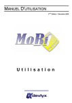
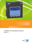
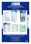
NGQUARK USER GUIDE www.promax.it NGQUARK USER GUIDE The informations contained in this document are for informational purposes only and are subject to change without notice and should not be interpreted by any commitment by Promax srl. Promax Ltd. assumes no responsibility or liability for errors or inaccuracies that may be found in this manual. Except as permitted by the license, no part of this publication may be reproduced, stored in a retrieval system or transmitted in any form or by any means, electronic, mechanical, recording or otherwise without prior permission Promax srl. Any references to company names and products are for demonstration purposes only and does not allude to any actual organization. Rev. 3.00.3 2 NGQUARK USER GUIDE 1 Features The system NGQUARK is a numerical control based on the Freescale MCF5213 ColdFire microprocessor. NGQUARK born as a stand alone and can also be used as SLAVE CANOPEN with appropriate firmware. NGQuark Microprocessor MCF 51JM128 at 48MHz 128 KbFlash 16 Kb RAM 16 kB FRAM permanent memory 2 Serial ports RS232 (1/RS485) 1 CAN OPEN Master/Slave 4 analog-innputs 12 bit 2 Analog Outputs +/-10V 11 Digital Inputs PNP 24 Vdc 8 Digital Outputs PNP 24 VDC up to 1 A 4 Channels STEP/DIR Line Drive o Open Collector 2 Ide ni fi cati on cod e ORDER CODE NG Quark NGQ/ - - - - 0 Without Analog Inputs or STEP/DIR Channels A 4 – Analog Inputs 5 V B 4 – Analog Inputs 12 V C 4 – Analog Inputs 10 V D 4 – Analog Inputs 4-20 Ma E 4 – Analog Inputs 24 V P 4 – STEP/DIR Channels Open Collector L2 2 – STEP/DIR Channels Line Drive L4 44 – STEP/DIR Channels Line Drive 0 SER1 RS232 - SER2 RS 232 1 SER1 RS232 - SER2 RS 485 0 Without Analog Outputs 1 2 – Analog Outputs +/- 10V A Default Analog Input 5 V B Default Analog Input 12 V C Default Analog Input 10 V D Default Analog Input 4-20 Ma E Default Analog Input 24 V The 4 analog inputs configuration excludes the default analog input 0 Without Expansion permanent memory 1 16 Kb Expansion permanent memory 3 NGQUARK USER GUIDE 4 N GQuar k Co nne cti on 4 NGQUARK USER GUIDE 5 C onn ect ion s de sc ripti on 5.1 Power The NGQuark requires two separate power supplies: Logical Power J3 Digital Outputs Power J1 e J2 To supply the digital outputs, see the relevant chapter 4.7. As regards the supply of the logic section, this is necessary for normal operation of the card. 5.1.1 Electrical Characteristics U.m. Min Standard Max DC In Vdc 12 24 35 Power (to 24Vdc) W PIN Description 1 + 24 VDC 2 CAN L 3 CAN H 4 GND 2,6 THE SYSTEM IS PROTECTED FROM POLARITY INVERSION WARNING DO NOT EXCEED THE MAXIMUM VOLTAGE VALUE ADMITTED BECAUSE THE CARD CAN BE DAMAGED 5 NGQUARK USER GUIDE 5.2 Serial Ports The serial ports on the NGQuark allow communication with external devices to the control, PC-type, PLC and other. SER1-PRG: is normally used both for the download of the programs on the control, both for the debugging from a PC application. It is also the port to use for updating the firmware SER2: Can be used for communication with other devices, such as a PLC, inverters or other. CAN BE CONFIGURED RS485 MODE. For the electrical signal, the serial ports are in compliance with RS232/RS485. Use a CABLE WITH SHIELD for serial ports connections Connect the SHIELD to PIN 5 SER1 or SER2 to NGQuark ports Generally the RS232 connection, uses a NULL MODEM cable (pin 2,3,5) CROSSOVER (with inversion on pin 2,3) Always check the external device that type of connection it accepts THE J6 CONNECTOR IS NOT IN STANDARD RS232 MODE SER1 and SER2 are connect to same connector J6 SER1 in RS232 mode SER2 in RS232 mode 6 NGQUARK USER GUIDE SER2 in RS485 mode Normally the GND pin is not connect 5.2.1 J6 Connections WARNING THE PIN 6 +3.3 Vdc MUST NOT BE CONNECTED ONLY FOR FUTURE EXPANSIONS WARNING DO NOT INSERT THE CONNECTORS PORT WHEN THE POWER IS ON BECAUSE THE CARD CAN BE DAMAGED 7 NGQUARK USER GUIDE 5.3 CAN BUS port The port CAN BUS allows the communication of the card NGQUARK with type devices for motors drives, slave of various kinds, encoders, and more. Communication takes place via the CAN OPEN protocol, based on its specifications DS401 and DS402 as regards the objects and the modes supported. In terms of data exchange, the line complies with DS301. The port can be configured as master or slave depending on the firmware present. The port CAN-BUS meets the specifications of ISO 11898-24V. 5.3.1 CAN BUS Connections If possible insert the terminator resistor with jumper JP1 5.3.2 CanOpen Max PDO Number Normally the max PDO number managed by NGQuark Canopen system , is 10. It is a total for PDO Rx and PDO Tx ex: 7 → PDO Tx 3 → PDO Rx WARNING USE THE CABLE FOR CANOPEN COMMUNICATION 8 NGQUARK USER GUIDE 5.3.3 Set Slave Node Number When the NGQUARK is in SLAVE MODE, you must select the CanOpen Node number by DIP 1. This is codified in binary mode (node 1 to 15) WARNING If the NGQuark board is configured as MASTER, insert always the TERMINATOR JUMPER If the NGQuark is configured as SLAVE, insert the TERMINATOR JUMPER if the board is the last node in the CanBus. In another situations, remove the JUMPER WARNING USE THE CABLE FOR CANOPEN COMMUNICATION 9 NGQUARK USER GUIDE 5.3.4 CanOpen Cable CONDUCTORS ELETTRIC RESISTANCE 22AWG: < 55,4 Ohm/Km 21AWG: < 43,6 Ohm/Km PAIR CAPACITY 50 pF/m IMPEDENCE 120 Ohm TRASMISSION SPEED-CABLE LENGTH Baud rate 1Mb Length Max 25 Mt Baud rate 800 Kb Length Max 50 Mt Baud rate 500 Kb Length Max 100 Mt Baud rate 250 Kb Length Max 250 Mt Baud rate 125Kb Length Max 500 Mt VOLTAGE EXERCISE 30 V 10 NGQUARK USER GUIDE 5.4 Analog Inputs The analog inputs of the NGQuark can be configured to read voltage signals including 5-10-12-24 VDC, or in current between 420mA. Configuration is done for each input, making the system very flexible. The input voltage can not exceed those limits by more than 0.2 V. They can be configured up to a maximum of 4 analog inputs, one of which is always present. 5.4.1 Analog Connections J4 5.4.2 Input Resistance MIN VDC Typical 25 Kῼ 72 Kῼ 175 ῼ 4-20 Ma 5.4.3 MAX Connection Example ATTENZIONE DO NOT EXCEED 0,2 Volt THE MAXIMUM VALUE SELECTED THE ANALOG INPUT, CAN BE DAMAGED THE 2 or MORE ANALOG INPUTS CONFIGURATION ESCLUDED THE OUTPUTS SETP/DIR 11 NGQUARK USER GUIDE 5.5 PULSE/DIR Outputs The card NGQuark can use, up to four outputs STEP / DIR for a total frequency of 125 Khz in position mode and 35 Khz in interpolation mode. The outputs can be configured with OPEN COLLECTOR signals, 5V or LINE DRIVE. 5.5.1 OPEN-COLLECTOR Signals POWER MAX 48 VDC LOAD 100 Ma continuative 500 Ma peak V STATE ON MIN 0V MAX 1V FREQUENCY MAX 30 Khz 5.5.2 LINE DRIVE Signals OUTPUT DIFFERENTIAL MIN 2.2V MAX 3.3V specific TIA/EIA-422-B (RS422)* FREQUENCY MAX 125 Khz in position mode – 35 Khz in interpolation mode specific TIA/EIA-422-B (RS422) LOAD V Min 3,9 Kῼ 100 ῼ V Typical 3,2 V 2 2,6 V ATTENZIONE USE A CABLE WITH SHIELD FOR THE CONNECTIONS THE STEP/DIR OUTPUTS CONFIGURATION ESCLUDED THE 4 ANALOG INPUTS The defualt analog input 1 is alway available 12 NGQUARK USER GUIDE 5.5.3 Connection STEP/DIR OPEN COLLECTOR J4 13 NGQUARK USER GUIDE 5.5.4 Connection STEP/DIR LINE DRIVE ATTENZIONE THE J10 CONNECTOR IS PRESENT ONLY IF USED CHANNELS LINE DRIVE 3 and 4 THIS CONNECTOR IS ON EXPANSION NGQ_EXP USE A CABLE WITH SHIELD FOR THE CONNECTIONS 14 NGQUARK USER GUIDE 5.6 Digital Inputs All these signals are PNP Tye optically isolated. Therefore, to enable an input must bring a positive VDC (24 Vdc typical) on the desired channel refers to the common inputs. 5.6.1 Electrical U.m. Min Standard Max State On Vdc 10 24 28 State Off Vdc 0 Delay 4 ON ms 3 (@ 24Vdc) OFF ms 2 (@ 24Vdc) Current mA 4 (10Vdc) 5.6.2 Connection J1 ATTENZIONE DO NOT EXCEED THE VOLTAGE LEVEL ABOVE DESCRIBED 15 14 (@ 28Vdc) NGQUARK USER GUIDE 5.7 Digital Outputs These outputs are optically isolated with respect to GND. In order to function should therefore feed them separately with a voltage of 24 Vdc. The load is driven by a transistor of the PNP type which when activated will provide a positive voltage equal to the voltage supply of the outputs. On the card there is a protection diode so you can also directly drive inductive loads. In case of inductive loads with absorption greater than or equal to 1 A or when the cable connection between the load and board exceeds a length of 3 meters, you should put the protection diode also close to the load (diode type 1N4007 or similar). 5.7.1 Electrical U.m. Min Standard Max Power Supply Vdc 10 24 30 Load A 1 Continue (T 25°) A 2 Duty Cycle 25% (T 25°) Delay 5.7.2 A 6 ON μs 5 OFF μs 30 Note Peak (10 ms) Connection J2 ATTENZIONE DO NOT EXCEED THE VOLTAGE LEVEL ABOVE DESCRIBED THE DIGITAL OUTPUTS, ARE NOT PROTECTED BY OVERLOAD OR SHORT CIRCUIT 16 NGQUARK USER GUIDE Expansion Board 5.8 The NGQ Expansion Board contain the following features: 2 Channels STEP/DIR Line Drive J10 See Chapr 4.5.4 2 Analog Outputs +/- 10 V J8 Permanent memory expansion FRAM 16 Kb Side view Up view 17 NGQUARK USER GUIDE 5.9 Analog Outputs The two Analog Outputs, are on the Expansion Board in the Connector J8 5.9.1 Electrical Analog Output Output Voltage Output impedence 5.9.2 U.m. Min Standard Vdc -10 9,995 Ω 250 290 Analog Outputs on J8 Expansion Board ATTENZIONE USE A CABLE WITH SHIELD FOR THE CONNECTIONS 18 Max NGQUARK USER GUIDE 6 Pro gram min g Manual Boot 6.1 The board usually uses an automatic boot. In case, the automatic boot is not available, it is necessary to proceed in the following way: 1) Run the program NGPROG (if used VTB skip step 2 and 3) 2) Set the COM and the type of card NGQUARK 3) Load the application. SREC and press TRANSFER APPLICATION 4) Press the keys simultaneously within 15 seconds RESET AND BOOT on the board 5) Release the RESET button Upload VTB application 6.2 For upload VTB application, is possible use the following mode: The board NGQUARK is automatically in BOOT MODE (if is not available, see 5.1) when you use the BUTTON UPLOAD APPLICATION. The application is automatically RUN when the transfer is finish. NGPROG 6.3 The application was developed by Promax NGPROG to allow the update software and firmware of the new controls based on μP ColdFire. 6.3.1 Upload firmware (If not present NGQUARK select NGM13) 1) Press button “GESTIONE FIRMWARE” on NGProg 2) If you use “UPDATE da File” use the standard windows Browser for find the .SREC file 2) If you use “UPDATE da Server” you must have a intenet active connection, NGPROG search in Promax server the new version of firmware 3) Select the serial port to PC and NGM13 board type 4) Start the upload firmware 6.3.2 1) 2) 3) 4) 7 Upload VTB application (If not present NGQUARK select NGM13) Select the NGM13 Board Select the COM on PC Selct the .SREC file by button “LOAD” Start the upload by button “TRASFERISCI APPLICAZIONE” Statu s Led ST-1/L1 (Green led): Fast blink – board in BOOT MODE blink1 sec – application RUN ST-2/L2 (Yellow led): NO BLINK - No activity on RS232 or CAN SLAVE BLINK - activity on RS232 or CAN SLAVE PWR (Red led): Power On 19 NGQUARK USER GUIDE 8 D im ensi on s 20 NGQUARK USER GUIDE 9 N otes on th e C E le gislatio n NGQuark complies all the legislation about CE tagging. We have two directives about electronic devices, regarding the NGQuark : la 2006/42/CE (machine directive) about safety use of the devices and 2004/108/CE about electromagnetic compatibility. About the first (machine directive) electric/electronic devices, must complies the "low voltage" directive (2006/95/CE) but it can be applied on devices supplied at 50-1000Vac o 75-1500Vdc. NGQUARK works at a voltage of 24Vdc (thus Intrinsically “safe” ), so it belongs to "very low voltage" devices (class 0 legislation CEI 11.1), on which it isn't no legislation about. On electromagnetic compatibility, regarding the 2004/108/CE norm, this device can be classified as a "finished appliance".Due to the fact that the NGQuark will be normally integrated inside a complex electromechanics system, the machine electric board, by a manufacturer in an industrial ambit and not by a final customer, it haven’t any certification duty. PROMAX however, can institute some specific measure as a pre-compliance, in case of particular demands of costumers, regarding the device electromagnetic characterization. For example, can be made some measure under the CEI EN 61000-6-1 norm (2007 generic norms – residential , commercial and light industrial ambient immunity) or CEI EN 61000-6-1 (2007 generic norms - residential , commercial and light industrial ambient emission) 21 NGQUARK USER GUIDE Index 1 Features .................................................................................................................................................................... 3 2 Idenification code..................................................................................................................................................... 3 3 ................................................................................................................................................................................... 3 4 NGQuark Connection ................................................................................................................................................ 4 5 Connections description ........................................................................................................................................... 5 5.1 Power ................................................................................................................................................................ 5 5.1.1 5.2 Electrical Characteristics ........................................................................................................................... 5 Serial Ports ........................................................................................................................................................ 6 5.2.1 J6 Connections .......................................................................................................................................... 7 ................................................................................................................................................................................... 7 ................................................................................................................................................................................... 7 5.3 CAN BUS port .................................................................................................................................................... 8 5.3.1 CAN BUS Connections ............................................................................................................................... 8 5.3.2 CanOpen Max PDO Number ..................................................................................................................... 8 5.3.3 Set Slave Node Number ............................................................................................................................ 9 5.3.4 CanOpen Cable ........................................................................................................................................ 10 5.4 Analog Inputs .................................................................................................................................................. 11 5.4.1 Analog Connections J4 ............................................................................................................................ 11 5.4.2 Input Resistance ...................................................................................................................................... 11 5.4.3 Connection Example ............................................................................................................................... 11 5.5 PULSE/DIR Outputs ......................................................................................................................................... 12 5.5.1 OPEN-COLLECTOR Signals ....................................................................................................................... 12 5.5.2 LINE DRIVE Signals................................................................................................................................... 12 5.5.3 Connection STEP/DIR OPEN COLLECTOR J4 ........................................................................................... 13 5.5.4 Connection STEP/DIR LINE DRIVE.......................................................................................................... 14 5.6 Digital Inputs ................................................................................................................................................... 15 5.6.1 Electrical .................................................................................................................................................. 15 5.6.2 Connection J1 .......................................................................................................................................... 15 5.7 Digital Outputs ................................................................................................................................................ 16 5.7.1 Electrical .................................................................................................................................................. 16 5.7.2 Connection J2 ......................................................................................................................................... 16 5.8 Expansion Board.............................................................................................................................................. 17 5.9 Analog Outputs ............................................................................................................................................... 18 5.9.1 Electrical .................................................................................................................................................. 18 5.9.2 Analog Outputs on J8 Expansion Board .................................................................................................. 18 22 NGQUARK USER GUIDE 6 Programming........................................................................................................................................................... 19 6.1 Manual Boot.................................................................................................................................................... 19 6.2 Upload VTB application ................................................................................................................................... 19 6.3 NGPROG .......................................................................................................................................................... 19 6.3.1 Upload firmware (If not present NGQUARK select NGM13) .................................................................. 19 6.3.2 Upload VTB application (If not present NGQUARK select NGM13) ........................................................ 19 7 Status Led ................................................................................................................................................................ 19 8 Dimensions.............................................................................................................................................................. 20 9 Notes on the CE legislation ..................................................................................................................................... 21 23