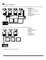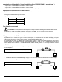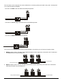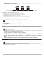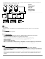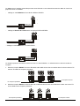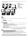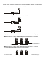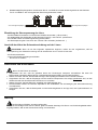
1
DTMRX1
MANUALE D’USO
__________________________
OPERATING INSTRUCTIONS
__________________________
MANUEL D’INSTRUCTIONS
__________________________
BEDIENUNGSANWEISUNG
DTMRX1
MANUALE
D’USO
INDICE
INDICE ............................................................................................................................................................................ 1
INTRODUZIONE ............................................................................................................................................................. 2
Contenuto dell’imballo........................................................................................................................................................................2
Cosa contiene questo manuale ..........................................................................................................................................................2
Convenzioni tipografiche ....................................................................................................................................................................2
NORME DI SICUREZZA.................................................................................................................................................. 2
DATI DI MARCATURA.................................................................................................................................................... 3
DESCRIZIONE DEL RICEVITORE DTMRX1 .................................................................................................................. 3
Caratteristiche ...................................................................................................................................................................................3
Apparecchi compatibili per l’uso con il ricevitore DTMRX1..................................................................................................................3
Esempi di installazioni .......................................................................................................................................................................4
Cavi...................................................................................................................................................................................................5
INSTALLAZIONE ............................................................................................................................................................ 6
Apertura dell’imballaggio....................................................................................................................................................................6
Controllo della marcatura...................................................................................................................................................................6
Dip-switch e jumper di configurazione ................................................................................................................................................6
CONFIGURAZIONE DEL RICEVITORE.......................................................................................................................... 7
Impostazione del numero di identificazione del ricevitore....................................................................................................................7
Impostazione della modalità di ricezione del ricevitore ( RS232 / RS485 / Current Loop ) ...................................................................8
Impostazione della velocità di comunicazione ....................................................................................................................................8
Tipo di ottiche controllate ...................................................................................................................................................................8
Collegamento con l’unità di comando.................................................................................................................................................8
Regolazione della tensione di controllo dell’ottica .............................................................................................................................10
Collegamento dei cavi del brandeggio e delle ottiche........................................................................................................................10
ACCENSIONE E SPEGNIMENTO ................................................................................................................................ 10
MANUTENZIONE.......................................................................................................................................................... 10
RISOLUZIONE DI PROBLEMI ...................................................................................................................................... 11
Il produttore declina ogni responsabilità per eventuali danni derivanti da un uso improprio delle apparecchiature
menzionate in questo manuale; si riserva inoltre il diritto di modificarne il contenuto senza preavviso.
Ogni cura é stata posta nella raccolta e nella verifica della documentazione contenuta in questo manuale: tuttavia il
produttore non può assumersi alcuna responsabilità derivante dall’utilizzo della stessa. Lo stesso dicasi per ogni
persona o società coinvolta nella creazione e nella produzione di questo manuale.
Pag. 1
DTMRX1 9922
Introduzione
Contenuto dell’imballo
• 1 ricevitore DTMRX1 manuale d’uso
• 2 tappi di chiusura PG11
• 4 staffe di fissaggio a muro con relative viti
Alla consegna del prodotto verificare che l’imballo sia integro e non abbia segni evidenti di cadute o abrasioni. In
caso di evidenti segni di danno all’imballo contattare immediatamente il fornitore.
Controllare che il contenuto sia rispondente alla lista del materiale sopra indicata.
Cosa contiene questo manuale
In questo manuale è descritto il ricevitore DTMRX1, con le particolari procedure di installazione, configurazione e
utilizzo. E’ necessario leggere attentamente questo manuale, in particolar modo il capitolo concernente le norme di
sicurezza, prima di installare ed utilizzare il ricevitore.
Convenzioni tipografiche
Nel presente manuale si fa uso di diversi simboli grafici, il cui significato è riassunto di seguito:
Rischio di scariche elettriche; togliere l’alimentazione prima di procedere con le operazioni, se non é
espressamente indicato il contrario.
L’operazione é molto importante per il corretto funzionamento del sistema: si prega di leggere attentamente la
procedura indicata, ed eseguirla secondo le modalità previste.
Descrizione delle caratteristiche del sistema: si consiglia di leggere attentamente per comprendere le fasi
successive.
Norme di sicurezza
Il ricevitore DTMRX1 é conforme alle normative vigenti all’atto della pubblicazione del presente manuale per
quanto concerne la sicurezza elettrica, la compatibilità elettromagnetica ed i requisiti generali.
Si desidera tuttavia garantire gli utilizzatori (tecnico installatore e operatore) specificando alcune avvertenze per
operare nella massima sicurezza:
• Collegare ad una linea di alimentazione corrispondente a quella indicata sulle etichette di marcatura (vedere il
successivo capitolo Dati di marcatura)
• La presa di alimentazione deve essere connessa a terra secondo le norme vigenti
• Prima di spostare o effettuare interventi tecnici sull’apparecchio, disinserire la spina di alimentazione
• Non utilizzare cavi di tensione con segni di usura o invecchiamento, in quanto rappresentano un grave pericolo
per l’incolumità degli utilizzatori
• L’installazione dell’apparecchio (e dell’intero impianto di cui esso fa parte) deve essere effettuata da personale
tecnico adeguatamente qualificato
• L’apparecchio deve essere aperto soltanto da personale tecnico qualificato. La manomissione dell’apparecchio fa
decadere i termini di garanzia
• Non utilizzare l’apparecchio in presenza di sostanze infiammabili
• Non permettere l’uso dell’apparecchio a bambini o incapaci
• Accertarsi che l’apparecchio sia fissato in maniera solida e affidabile
• L’apparecchio si considera disattivato soltanto quando l’alimentazione é disinserita e i cavi di collegamento con
altri dispositivi sono stati rimossi
• Per l’assistenza tecnica rivolgersi esclusivamente al personale tecnico autorizzato
• Conservare con cura il presente manuale per ogni futura consultazione
Pag. 2
DTMRX1 9922
Dati di marcatura
Sul ricevitore DTMRX1 sono riportate due etichette.
La prima etichetta contiene:
• Codice di identificazione del modello (Codice a barre Extended 3/9 )
• Tensione di alimentazione (Volt)
• Frequenza (Hertz)
• Consumo (Watt)
La seconda etichetta indica il numero di serie del modello (codice a barre Extended 3/9)
All’atto dell’installazione controllare se le caratteristiche di alimentazione del ricevitore corrispondono a quelle
richieste. L’uso di apparecchi non idonei può portare a gravi pericoli per la sicurezza del personale e dell’impianto.
Descrizione del ricevitore DTMRX1
Il ricevitore DTMRX1 è un ricevitore di comandi a microprocessore per il controllo remoto di brandeggi e
ottiche motorizzate.
Caratteristiche
• 12 Funzioni : UP, DOWN, LEFT, RIGHT, AUTO, ZOOM TELE, ZOOM WIDE, FOCUS NEAR, FOCUS FAR, IRIS
OPEN, IRIS CLOSE, AUX
• AUX: contatto ausiliario pulito 1A 230 Vac, 1A 24 V#
• 99 indirizzi selezionabili tramite Dip switch
• Ingresso seriale selezionabile tra RS232, RS485 e Current Loop
• Velocità di comunicazione selezionabile (9600 / 1200 Baud)
• Ripetitore RS232, RS485 e Current Loop per configurazione in cascata
• Possibilità di usare sia ottiche funzionanti ad inversione di polarità che ottiche funzionanti a filo comune
• Logica digitale e parte di potenza optoisolate
• EEPROM per memorizzazione opzioni attivate
• Led presenza alimentazione
• Led ricezione comando
• Led ricezione dati
• Tensione di alimentazione:
230 V~ 50Hz; 24V~ 50/60Hz
(riferirsi ai dati di marcatura)
• Consumo:
10 W
• Max potenza commutabile:
100 W
• Tensione alimentazione brandeggio:
230 V~ 50Hz; 24V~ 50/60Hz
(riferirsi ai dati di marcatura)
• Tensione alimentazione ottica:
6/16 V= max 80 mA
• Fusibile:
F1: 1,6 AF 250V
versione 24V~
F1: 250 mAF 250V
versione 230V~
Apparecchi compatibili per l’uso con il ricevitore DTMRX1
• DCS2, DCMT8, DCS3: tastiere di controllo.
• controllore di comunicazioni DCMX: permette di controllare uno o più ricevitori da parte di più tastiere (fino a 4).
Fare riferimento ai singoli manuali d’uso per una descrizione completa delle caratteristiche degli apparecchi.
Pag. 3
DTMRX1 9922
Esempi di installazioni
Un operatore con più monitor, con controllo di una serie di brandeggi in configurazione mista (a stella e in cascata)
DTMRX1
DTMRX1
DTMRX1
DCMX
DTMRX1
MATERIALE
Parte di controllo:
1 tastiera di controllo DCS2
Parte video:
1 commutatore video SW164OSM
2 monitor
4 telecamere
Parte telemetria:
1 controllore di comunicazioni DCMX
4 ricevitori DTMRX1
4 brandeggi
SW164OSM
DCS2
Un operatore senza matrice video, con controllo di tre ricevitori collegati in cascata
PTH
PTH
DTMRX1
DTMRX1
MATERIALE
Parte di controllo:
1 tastiera di controllo DCS2
Parte video:
3 monitor
3 telecamere
Parte telemetria:
3 ricevitori DTMRX1
3 brandeggi
PTH
DTMRX1
DCS2
DCS2
PRESE T
SCA N
A UX 1
AUX 2
A UX 3
AUX 4
CO M FAU LT
M /A
ALAR M
P ROG
WIPER
- /- -
1
6
2
7
3
8
4
9
5
0
C LEAR
IN
O PEN
N EAR
E NTER
USER
OU T
C LO SE
FAR
La descrizione dei cavi è alla pagina seguente.
Pag. 4
DTMRX1 9922
Tre operatori con un monitor ciascuno, con controllo di un gruppo di ricevitori da parte di due di loro; il terzo effettua
soltanto operazioni di commutazione video
PTH
PTH
DTMRX1
PTH
DTMRX1
DTMRX1
SW164OSM
SW16.4
DCMX
DCMX
DCS2
DCS2
DCS2
DCS2
PR ESET
S CAN
AU X 1
A UX 2
AU X 3
A UX 4
PR ESET
AU X 1
A UX 2
ALARM
2
3
4
5
7
8
9
0
M /A
AUX 3
ALAR M
A UX 4
P ROG
PRO G
WIPE R
1
6
COM FAULT
M/A
M/A
PR OG
-/--
KEYPLUS
KEYPLUS
S CAN
COM FAULT
COM FAULT
ALARM
MATERIALE
Parte di controllo:
2 tastiere di controllo DCS2
1 tastiera di controllo KEYPLUS
Parte video:
3 monitor
3 telecamere
Parte telemetria:
3 ricevitori DTMRX1
3 brandeggi
1 multiplexer digitale DCMX
WIPE R
IN
CLE AR
OPE N
NE AR
EN TER
U SER
OUT
CLO SE
FAR
-/--
1
2
3
4
5
6
7
8
9
0
CLEA R
IN
OPE N
EN TE R
U SER
O UT
CLO SE
NE AR
FAR
-/--
1
2
3
4
5
6
7
8
9
0
CLEAR
ENTER
Cavi
Negli schemi d’esempio sono stati utilizzati di versi tipi di tratto per indicare cavi di diversa funzione:
cavo video:
coassiale RG 59 o cavo equivalente.
cavo multipolare:
ogni funzione di controllo del brandeggio viene attivata / disattivata da un relè interno al ricevitore.
Stabilire il numero finale di cavi, seguendo le indicazioni seguenti:
7 fili per la movimentazione del brandeggio: destra, sinistra, alto, basso, autopan, comune, terra
6 fili di controllo per ottiche ad inversione di polarità (zoom, focus, iris)
4 fili di controllo per ottiche a filo comune (zoom, focus, iris)
2 fili per l’ ausiliare
3 fili per cavo alimentazione
Nota: è consigliato l’utilizzo di differenti cavi multipolari per le funzioni in bassa tensione ed in alta tensione.
Sezione minima consigliata:
0,56 mm.² (AWG 20) per fili in alta tensione (brandeggio)
0,34 mm.² (AWG 22) per fili in bassa tensione (ottica, ausiliare)
0,75 mm.² (AWG 18) per fili alimentazione DTMRX1
cavo per la ricezione/trasmissione digitale dei comandi:
2 fili per la ricezione dall’unità di comando (doppino telefonico twistato, sezione 0,22 mm.² AWG 24)
2 fili per la eventuale trasmissione al ricevitore successivo nelle configurazione in cascata (doppino telefonico
twistato, sezione 0,22 mm.² AWG 24)
Nota: la distanza massima del collegamento é di circa 15 m in RS232; 1200 m in RS485; 1500 m in Current Loop.
Quando più ricevitori sono collegati in cascata, è necessario utilizzare due cavi separati per la ricezione e la
trasmissione digitale dei comandi ( non utilizzare cavi multicoppia ) tra i ricevitori
Pag. 5
DTMRX1 9922
Installazione
La fase di installazione deve essere effettuata solo da personale tecnico qualificato.
Le seguenti procedure sono da effettuare in assenza di alimentazione, se non diversamente indicato.
Apertura dell’imballaggio
Se l’imballo non presenta evidenti difetti (dovuti a cadute o abrasioni anomale), procedere al controllo del materiale
in esso contenuto, secondo la lista fornita al paragrafo Contenuto dell’imballo al capitolo Introduzione.
I materiali d’imballo sono costituiti interamente da materiale riciclabile. Sarà cura del tecnico installatore smaltirli
secondo le modalità di raccolta differenziata o comunque secondo le norme vigenti nel Paese di utilizzo.
Controllo della marcatura
Prima di procedere con l’installazione controllare se il materiale fornito corrisponde alle specifiche richieste,
esaminando le etichette di marcatura, secondo quanto descritto al capitolo Descrizione della marcatura.
Non effettuare per nessun motivo alterazioni o collegamenti non previsti in questo manuale: l’uso di apparecchi non
idonei può portare a gravi pericoli per la sicurezza del personale e dell’impianto.
Dip-switch e jumper di configurazione
Nello schema seguente identificare i Dip-switch e i jumpers di configurazione :
SW1
TR1
1 2 3 4 5 6 7 8
LD1
SW1
1 2 3 4 5 6 7 8
LD3 LD2
F1
RS232
RS485
CLOOP
JP1
RS232
RS485
CLOOP
J3
JP1
J2
J1
RJ11
Pag. 6
DTMRX1 9922
Configurazione del ricevitore
La fase di configurazione del ricevitore consente di predisporlo ad un funzionamento ottimale, in base alle
necessità dell’impianto. La configurazione deve essere fatta solo al momento dell’installazione da parte del tecnico
installatore.
Si consiglia di procedere con ordine alla configurazione dei parametri, per evitare problemi di installazione.
I parametri impostati in fase di configurazione sono:
• Numero di identificazione del ricevitore
• Modalità di ricezione del ricevitore ( RS232 / RS485 / Current Loop )
• Impostazione della velocità di comunicazione ( 9600 / 1200 Baud)
• Collegamento delle ottiche
• Collegamento all’unità di comando
• Regolazione della tensione di controllo dell’ottica
• Collegamento dei cavi del brandeggio e delle ottiche
Impostazione del numero di identificazione del ricevitore
- assicurarsi che non sia presente l’alimentazione ( led LD1 spento )
- configurare il dip-switch SW1 secondo la tabella seguente :
01
02
03
04
05
06
07
08
09
10
11
12
13
14
15
16
17
18
19
20
21
22
23
24
25
26
27
28
29
30
31
32
33
DIP-SWITCH
1234 5678
+--- ----+-- ---++-- -----+- ---+-+- ----++- ---+++- ------+ ---+--+ ----+-+ ---++-+ -----++ ---+-++ ----+++ ---++++ ------- +--+--- +---+-- +--++-- +----+- +--+-+- +---++- +--+++- +-----+ +--+--+ +---+-+ +--++-+ +----++ +--+-++ +---+++ +--++++ +------ -+-+--- -+--
34
35
36
37
38
39
40
41
42
43
44
45
46
47
48
49
50
51
52
53
54
55
56
57
58
59
60
61
62
63
64
65
66
DIP-SWITCH
1234 5678
-+-- -+-++-- -+---+- -+-+-+- -+--++- -+-+++- -+----+ -+-+--+ -+--+-+ -+-++-+ -+---++ -+-+-++ -+--+++ -+-++++ -+----- ++-+--- ++--+-- ++-++-- ++---+- ++-+-+- ++--++- ++-+++- ++----+ ++-+--+ ++--+-+ ++-++-+ ++---++ ++-+-++ ++--+++ ++-++++ ++----- --++--- --+-+-- --+-
67
68
69
70
71
72
73
74
75
76
77
78
79
80
81
82
83
84
85
86
87
88
89
90
91
92
93
94
95
96
97
98
99
Pag. 7
DIP-SWITCH
1234 5678
++-- --+--+- --++-+- --+-++- --++++- --+---+ --++--+ --+-+-+ --+++-+ --+--++ --++-++ --+-+++ --+++++ --+---- +-++--- +-+-+-- +-+++-- +-+--+- +-++-+- +-+-++- +-++++- +-+---+ +-++--+ +-+-+-+ +-+++-+ +-+--++ +-++-++ +-+-+++ +-+++++ +-+---- -+++--- -++-+-- -++++-- -++-
DTMRX1 9922
Impostazione della modalità di ricezione del ricevitore ( RS232 / RS485 / Current Loop )
- jumper JP1 in posizione RS232 : modalità di ricezione RS232
- jumper JP1 in posizione RS485 : modalità di ricezione RS485
- jumper JP1 in posizione CLOOP: modalità di ricezione Current Loop (impostazione di default)
Impostazione della velocità di comunicazione
Il DTMRX1 può effettuare comunicazioni con una velocità di 9600 o 1200 baud.
Dove agire: interruttore 8 del dip-switch SW1
Impostazioni:
Interruttore 8
Velocità
OFF
9600 baud *
ON
1200 baud
* Impostazione di default
Tipo di ottiche controllate
ATTENZIONE: Il collegamento errato del tipo di ottiche può causare il danneggiamento delle ottiche stesse.
Il DTMRX1 è in grado di controllare sia ottiche a inversione di polarità, sia a filo comune. In caso di ottiche
funzionanti a filo comune collegare il filo comune a FOCUS -
Collegamento con l’unità di comando
Il connettore RJ11 presente nel circuito consente la ricezione e la trasmissione di dati digitali in RS232 o Current
Loop consentendo un rapido collegamento delle varie apparecchiature durante eventuali fasi di test, oppure per il
collegamento di interfacce di conversione presenti sul mercato (RS232-fibra ottica...).
Per il collegamento finale, con tastiere DCS2 e DCMT8, si consiglia di usare la modalità Current Loop ed i relativi
morsetti presenti sul circuito (la distanza massima raggiungibile è di 1500 m); per il collegamento finale con la
tastiera DCS3 si deve utilizzare la modalità RS485 ed i relativi morsetti presenti nel circuito (la distanza massima
raggiungibile è di 1200 m).
- modalità di collegamento RS232 : collegare i cavi provenienti dal comando mediante le scatole RJ jack secondo lo
schema seguente :
DCS2/DCMT8
Nero Tx RS232
Verde GND RS232
-----------------------
DTMRX1
Giallo Rx RS232
Rosso GND RS232
DCMT8
-
DTMRX1
modalità di collegamento Current Loop : collegare i cavi provenienti dal comando mediante le scatole RJ jack
secondo lo schema seguente :
DCS2/DCMT8
Giallo Tx CL
Rosso GND CL
-----------------------
DTMRX1
Nero Rx CL
Verde GND CL
Pag. 8
DCMT8
DTMRX1
DTMRX1 9922
Il collegamento con l’unità di comando può essere realizzato anche collegando direttamente il cavo proveniente dalla
tastiera alla morsettiera del DTMRX1:
-
collegamento in modalità RS232 con tastiere DCS2 e DCMT8:
TX RS232 (nero)
GND RS232 (verde)
-
collegamento in modalità Current Loop con tastiere DCS2 e DCMT8:
TX CL (giallo)
GND CL (rosso)
-
collegamento in modalità RS485 con la tastiera DCS3:
TX RS485B (giallo)
TX RS485A (bianco)
Il ricevitore può essere collegato in cascata ad un’altra unità DTMRX1, selezionando una delle tre modalità di
ricezione:
1) Modalità di ricezione RS485: i morsetti RX-485A e RX-485B devono essere collegati, rispettivamente, ai morsetti
Al ricevitore successivo
Dal ricevitore precedente
TX-485A e TX-485B dell’unità precedente.
2) Modalità di ricezione RS232: i morsetti RX-232 e GND-232 devono essere collegati, rispettivamente, ai morsetti
TX-232 e GND-232 dell’unità precedente.
Dal ricevitore precedente
Al ricevitore successivo
Pag. 9
DTMRX1 9922
3) Modalità di ricezione Current Loop: i morsetti RX-CL e GND-CL devono essere collegati, rispettivamente, ai
morsetti TX-CL e GND-CL dell’unità precedente.
Dal ricevitore precedente
Al ricevitore successivo
Regolazione della tensione di controllo dell’ottica
- collegare il cavo di alimentazione e alimentare l’unità DTMRX1 ( LD1 acceso )
- posizionare i puntali del tester sui morsetti FOCUS+ e FOCUS- tenere premuto il tasto FOCUS NEAR sull’unità di comando
- regolare la tensione di controllo dell’ottica agendo sul trimmer TR1 ( default 12V )
Collegamento dei cavi del brandeggio e delle ottiche
ATTENZIONE : Prima di effettuare le seguenti operazioni assicurarsi che la tensione di controllo del
brandeggio e l’impostazione del tipo di ottiche utilizzati siano corretti
- Togliere alimentazione all’unità
- Effettuare i collegamenti con ottica e brandeggio
- Alimentare l’unità
Accensione e spegnimento
Prima di fornire alimentazione:
• controllare se il materiale fornito corrisponde alle specifiche richieste, esaminando le etichette di marcatura,
secondo quanto descritto al capitolo Descrizione della marcatura.
• controllare che i fusibili di protezione del ricevitore DTMRX1 siano integri
• controllare che il ricevitore e gli altri componenti dell’impianto siano chiusi e sia quindi impossibile il contatto
diretto con parti in tensione.
• accertarsi che tutte le parti siano fissate in maniera solida ed affidabile
• i cavi di alimentazione non devono essere d’intralcio alle normali operazioni del tecnico installatore ed al
movimento del brandeggio
• controllare che le fonti di alimentazione ed i cavi di collegamento siano in grado di sopportare il consumo del
sistema
Manutenzione
Il ricevitore DTMRX1 non necessita di particolare manutenzione.
Si raccomanda di utilizzarlo poggiato su una base solida, con i cavi di alimentazione e di collegamento in posizione
tale da non essere causa di intralcio all’operatore.
Pag. 10
DTMRX1 9922
Risoluzione di problemi
Il ricevitore DTMRX1 è caratterizzato da una notevole facilità d’uso, ma ciononostante possono insorgere dei
problemi sia in fase di installazione, di configurazione o durante l’uso.
Il led LD1 è spento
Il led LD1 è acceso.
Non vengono eseguiti i
comandi
•
•
•
•
•
•
Manca alimentazione
Fusibile bruciato
Configurazione errata della ricezione
Collegamento non corretto
Identificazione DTMRX1 errata
Velocità errata
•
•
•
•
•
•
Il brandeggio non funziona
• Alimentazione del brandeggio errata
•
L’ottica non funziona
• Tensione ottica errata
•
In un collegamento a
cascata, le unità
successive non ricevono
comandi
• Collegamento non corretto
• Configurazione errata della ricezione
• Velocità errata
•
•
•
Pag. 11
Controllare il cavo di alimentazione
Sostituire il fusibile F1
Controllare il jumper JP1
Controllare i cavi di collegamento e le
scatole RJ jack
Controllare il numero di identificazione
del DTMRX1
Verificare interruttore 8 del dip-switch
SW1
Controllare che la tensione di
alimentazione del brandeggio
corrisponda a quella fornita dal
ricevitore
Controllare la regolazione del trimmer
TR1
Controllare i cavi di collegamento
Controllare il jumper JP1
Verificare interruttore 8 del dip-switch
SW1
DTMRX1 9922
DTMRX1
OPERATING
INSTRUCTIONS
TABLE OF CONTENTS
TABLE OF CONTENTS .................................................................................................................................................. 1
INTRODUCTION ............................................................................................................................................................. 2
Contents of the packaging..................................................................................................................................................................2
Contents of this manual .....................................................................................................................................................................2
Typographical conventions.................................................................................................................................................................2
SAFETY RULES ............................................................................................................................................................. 2
OPERATING DATA ON THE RATING PLATE ............................................................................................................... 3
DESCRIPTION OF THE DTMRX1 RECEIVER................................................................................................................ 3
Features ............................................................................................................................................................................................3
Compatible devices............................................................................................................................................................................3
Installation examples .........................................................................................................................................................................4
Cables ...............................................................................................................................................................................................5
INSTALLATION .............................................................................................................................................................. 6
Unpacking .........................................................................................................................................................................................6
Control of the operating data on the rating plate .................................................................................................................................6
Dip-switches and configuration jumpers .............................................................................................................................................6
CONFIGURATION OF THE RECEIVER.......................................................................................................................... 7
To set the identification number of the receiver...................................................................................................................................7
To set the reception mode of the receiver ( RS232 / RS485 / Current Loop ).......................................................................................8
To set the communication rate ...........................................................................................................................................................8
Type of lenses controlled ...................................................................................................................................................................8
Connection with the control unit .........................................................................................................................................................8
To adjust the control voltage of the lens ...........................................................................................................................................10
Connection of the cables of the positioning device and the lens ........................................................................................................10
SWITCHING ON AND SWITCHING OFF ...................................................................................................................... 10
MAINTENANCE ............................................................................................................................................................ 10
TROUBLESHOOTING .................................................................................................................................................. 11
The manufacturer assumes no responsability for possible damages resulting from an improper use of the devices
mentioned in this manual; moreover he reserves the right to change the contents of the present manual without
notice.
The documentation contained in this manual has been gathered and examined with great care; nevertheless the
manufacturer can not assume any responsability resulting from the use of such documentation. The same is valid for
any other person or society involved in the creation and in the production of the present manual.
Page 1
DTMRX1 9922
Introduction
Contents of the packaging
• 1 DTMRX1 receiver
• 1 this instruction manual
• 2 PG11 blanking caps
• 4 wall mounts with relevant fastening screws
On delivery, please make sure that the packaging does not present damages or evident signs of falls or scratches. In
case of evident damages, contact immediately the supplier.
Please, make sure that the contents correspond to the components list mentioned above.
Contents of this manual
This manual contains the description of the DTMRX1 receiver, with the relevant installation, configuration and use
procedures. Before installing and using the receiver it is necessary to read carefully the present manual, in
particular the section concerning the safety rules.
Typographical conventions
The following section illustrates the meaning of graphic symbols used in the present manual:
Risk of electric shock; before proceeding with the operations, if not otherwise stated, disconnect the unit.
The operation is very important for the correct functioning of the system: please read carefully the procedure
indicated and carry it out according to the prescribed specifications.
Description of the system features; we recommend reading carefully the sections marked with this symbol in
order to understand the phases which follow.
Safety rules
The DTMRX1 receiver complies with the rules in force at the time of publication of the present manual as
regards the electric safety, the electromagnetic compatibility and the other general requirements.
Nevertheless we would like to assure the users (installer and operator) illustrating some measures to be adopted in
order to guarantee the maximum safety:
• Connect the unit to a power supply corresponding to the one indicated on the rating plate (see next section
Operating data on the rating plate)
• The outlet must be adequatly grounded according to the rules in force
• Before moving or carrying out technical operations on the unit, disconnect it
• Do not use worn or damaged power cords, since they represent a serious risk for the user’s safety
• The installation of the unit (and of the whole plant of which this unit is part) must be carried out by adequately
skilled technical personnel
• The unit must be opened only by skilled technical personnel. The warranty limits does not cover damages
resulting from an improper use of the unit
• Do not use the device in areas containing inflammable substances
• Do not allow children or unskilled persons to use the unit
• Make sure that the unit is fixed securely and firmly
• The unit is considered off-line only when the power supply is disconnected and the cables aimed to connect the
unit with other devices have been removed
• For the after-sales service, please contact exclusively the authorized technical personnel
• Keep the present manual with care for any future consultation
Page 2
DTMRX1 9922
Operating data on the rating plate
The DTMRX1 receiver is supplied with two rating plates.
The first plate contains:
• Model identification code (Extended 3/9 bar code)
• Power supply (Volt)
• Frequency (Hertz)
• Power consumption (Watt)
The second label indicates the serial number of the model (Extended 3/9 bar code).
During the installation phase, make sure that the power supply features of the receiver correspond to the
characteristics required. The use of unsuitable devices can lead to serious risks for the safety of the personnel and
the security of the plant.
Description of the DTMRX1 receiver
The DTMRX1 receiver is a microprocessor-based command receiver for remote control of positioning devices
and motorized lenses.
Features
• 12 Functions: UP, DOWN, LEFT, RIGHT, AUTO, ZOOM TELE, ZOOM WIDE, FOCUS NEAR, FOCUS FAR, IRIS
OPEN, IRIS CLOSE, AUX
• AUX: auxiliary clean contact 1A 230Vac, 1A 24V#
• 99 identification addresses, selectable by Dip switch
• Serial communication selectable between RS-232, RS485 and Current Loop
• Communication rate setting (9600 / 1200 Baud)
• RS232, RS485 and Current Loop repeater for in-cascade configuration
• Possibility of using both polarity inversion lenses and common wire lenses
• Optoisolated digital logic and power section
• EEPROM for storing activated options
• Led indicating power supplied to the unit
• Led indicating command reception
• Led indicating data reception
• Power supply:
230 V~ 50Hz; 24V~ 50/60Hz:
refer to Operating data on rating plate
• Power consumption:
10 W
• Max swichtable power:
100 W
• Power supplied to the positioning device: 230 V~ 50Hz; 24V~ 50/60Hz
refer to Operating data on rating plate
• Power supplied to the lens:
from 6 to 16V=
max 80 mA
• Protection fuses:
F1: 1,6 AF 250V
version 24V~
F1: 250 mAF 250V
version 230V~
Compatible devices
• DCS2, DCMT8 and DCS3: control keyboards.
• communication controller DCMX: it allows the operator to control up to 8 line of receivers by means of up yo 4
control keyboards
Please refer to each user’s manual for a complete description of the features of the single units.
Page 3
DTMRX1 9922
Installation examples
Example no.1: a single operator with several monitors, controlling a set of receivers in mixed configuration (star and
cascade - chain configuration)
DTMRX1
DTMRX1
DTMRX1
DEVICES
Control section:
1 DCS2 control keyboard
Video section:
1 SW164OSM video switcher
2 monitors
4 cameras
Telemetry section:
1 DCMX serial data multiplexer
4 DTMRX1 receivers
4 positioning devices
DTMRX1
DCMX
SW164OSM
DCS2
Example no.2: a single operator without video matrix for the control of three cascade-connected receivers
PTH
PTH
DTMRX1
DTMRX1
DEVICES
Control section:
1 DCS2 control keyboard
Video section:
3 monitors
3 cameras
Telemetry section:
3 DTMRX1 receivers
3 positioning devices
PTH
DTMRX1
DCS2
DCS2
PRESE T
SCA N
A UX 1
AUX 2
A UX 3
AUX 4
CO M FAU LT
M /A
ALAR M
P ROG
WIPER
- /- -
1
6
2
7
3
8
4
9
5
0
C LEAR
IN
O PEN
N EAR
E NTER
USER
OU T
C LO SE
FAR
The description of the cables is on the following page.
Page 4
DTMRX1 9922
Example no.3: three operators with a monitor for each one; two of them control a set of receivers; the third carries out
only video switching operations.
PTH
PTH
DTMRX1
PTH
DTMRX1
DTMRX1
SW164OSM
SW16.4
DCMX
DCMX
DCS2
DCS2
DCS2
DCS2
PR ESET
S CAN
AU X 1
A UX 2
AU X 3
A UX 4
PR ESET
AU X 1
S CAN
A UX 2
ALARM
2
3
4
5
7
8
9
0
M /A
AUX 3
ALAR M
A UX 4
P ROG
PRO G
WIPE R
1
6
COM FAULT
M/A
M/A
PR OG
-/--
KEYPLUS
KEYPLUS
COM FAULT
COM FAULT
ALARM
DEVICES
Control section:
2 DCS2 control keyboard
1 KEYPLUS control keyboard
Video section:
3 monitors
3 cameras
Telemetry section:
3 DTMRX1 receivers
3 positioning devices
1 DCMX digital multiplexer
WIPE R
IN
CLE AR
OPE N
NE AR
EN TER
U SER
OUT
CLO SE
FAR
-/--
1
2
3
4
5
6
7
8
9
0
CLEA R
IN
OPE N
EN TE R
U SER
O UT
CLO SE
NE AR
FAR
-/--
1
2
3
4
5
6
7
8
9
0
CLEAR
ENTER
Cables
Different types of stroke have been used in the previous examples, in order to indicate cables with different functions:
video cable:
RG 59 coaxial cable or equivalent cable
multipolar cable:
each control function of the positioning device is activated /deactivated by a relay positioned inside the receiver.
Fix the final numbers of wires according to the following directions:
7 wires for the motion of the positioning device: right, left, up, down, autopan, common, ground
6 wires for the control of polarity reversal lenses (zoom, focus, iris)
4 wires for the control of common wire lenses (zoom, focus, iris)
2 wires for the auxiliary device
3 wires for power cord
Note: We recommend the use of different multipolar cables for high tension and low tension functions.
Minimum section area recommended: 0.56 mm.² (AWG 20) for high tension wires (positioning device)
0.34 mm.² (AWG 22) for low tension wires (lens, auxiliary device)
0.75 mm.² (AWG 18) for power wires of DTMRX1
cable for the digital receiving / transmission of commands:
2 wires for to receive from the control unit (twisted telephone pair, section 0.22 mm.² AWG 24)
2 wires for the possible transmission to the next cascade-connected receiver (twisted telephone pair, section
0.22 mm.² AWG 24)
Note: Maximum distance for the connection: about 15 m in RS232; 1200 m in RS485; 1500 m in Current Loop.
If many receivers are cascade-connected, it is necessary to use two separated cables for the digital reception
and transmittion of commands (do not use multicouple cable) between the receivers
Page 5
DTMRX1 9922
Installation
The unit must be installed exclusively by skilled technical personnel.
Before carrying out the following operations, if not otherwise stated, always disconnect the unit from power
supply.
Unpacking
If the packaging does not present evident faults (due to falls or anomalous scratches), make sure that its contents
correspond to the list of items contained in paragraph Contents of the packaging, in section Introduction.
The installer will take care to dispose it according to the recycling programs or, in any case, according to the rules in
force in the country of destination.
Control of the operating data on the rating plate
Before installing the unit, control if the goods supplied correspond to the required specifications by examining
the rating plates, according to the section Operating data on the rating plate.
Never make alterations or connections not provided for in the present manual: the use of unsuitable devices can lead
to serious risks for the safety of the personnel and the security of the plant.
Dip-switches and configuration jumpers
In the following schema identify the Dip-switches and the jumpers of configuration :
SW1
TR1
1 2 3 4 5 6 7 8
LD1
SW1
1 2 3 4 5 6 7 8
LD3 LD2
F1
RS232
RS485
CLOOP
JP1
RS232
RS485
CLOOP
J3
JP1
J2
J1
RJ11
Page 6
DTMRX1 9922
Configuration of the receiver
The receiver configuration phase allows to optimize its functioning according to the particular requirements of
the plant. The unit must be configured exclusively during the installation phase and by an installer.
We recommend proceeding with the configuration of the parameters in a systematic way in order to avoid installation
troubles.
The parameters set during the configuration phase are the following:
• Identification number of the receiver
• Reception mode of the receiver (RS232 / RS485 / Current Loop)
• Communication rate setting (9600 / 1200 Baud)
• Connection of lenses
• Connection with the control unit
• Adjustment of the control voltage of the lens
• Connection of the cables of the positioning device and the lenses
To set the identification number of the receiver
- make sure that the unit is disconnected from the power supply (LD1 Led off)
- configure the SW1dip-switch according to the following table:
01
02
03
04
05
06
07
08
09
10
11
12
13
14
15
16
17
18
19
20
21
22
23
24
25
26
27
28
29
30
31
32
33
DIP-SWITCH
1234 5678
+--- ----+-- ---++-- -----+- ---+-+- ----++- ---+++- ------+ ---+--+ ----+-+ ---++-+ -----++ ---+-++ ----+++ ---++++ ------- +--+--- +---+-- +--++-- +----+- +--+-+- +---++- +--+++- +-----+ +--+--+ +---+-+ +--++-+ +----++ +--+-++ +---+++ +--++++ +------ -+-+--- -+--
34
35
36
37
38
39
40
41
42
43
44
45
46
47
48
49
50
51
52
53
54
55
56
57
58
59
60
61
62
63
64
65
66
DIP-SWITCH
1234 5678
-+-- -+-++-- -+---+- -+-+-+- -+--++- -+-+++- -+----+ -+-+--+ -+--+-+ -+-++-+ -+---++ -+-+-++ -+--+++ -+-++++ -+----- ++-+--- ++--+-- ++-++-- ++---+- ++-+-+- ++--++- ++-+++- ++----+ ++-+--+ ++--+-+ ++-++-+ ++---++ ++-+-++ ++--+++ ++-++++ ++----- --++--- --+-+-- --+-
67
68
69
70
71
72
73
74
75
76
77
78
79
80
81
82
83
84
85
86
87
88
89
90
91
92
93
94
95
96
97
98
99
DIP-SWITCH
1234 5678
++-- --+--+- --++-+- --+-++- --++++- --+---+ --++--+ --+-+-+ --+++-+ --+--++ --++-++ --+-+++ --+++++ --+---- +-++--- +-+-+-- +-+++-- +-+--+- +-++-+- +-+-++- +-++++- +-+---+ +-++--+ +-+-+-+ +-+++-+ +-+--++ +-++-++ +-+-+++ +-+++++ +-+---- -+++--- -++-+-- -++++-- -++-
Page 7
DTMRX1 9922
To set the reception mode of the receiver ( RS232 / RS485 / Current Loop )
- jumper JP1 set to RS232 position: RS232 reception mode
- jumper JP1 set to RS485 position: RS485 reception mode
- jumper JP1 set to CLOOP position: Current Loop reception mode (default setting)
To set the communication rate
The DTMRX1 receiver is able to communicate with a rate of 9600 or 1200 baud.
Where to operate: switch 8 of dip-switch SW1
Setting:
switch 8
Comm.rate
OFF
9600 baud *
ON
1200 baud
* default setting
Type of lenses controlled
WARNING: The wrong connection of the type of lenses can cause the damage of the lenses themselves.
The DTMRX1 receiver is able to control both the reversal polarity lenses and the common wire lenses. In case of
lenses working in common wire connect the common wire to FOCUS -
Connection with the control unit
The RJ11 connector supplied to the circuit enables the reception and the transmission of digital data in RS232 or
Current Loop, allowing a rapid connection of several units in case of test runs or for the connection of conversion
interfaces available on the market (RS232-optical fiber...).
For the final connection, by the DCS2 and DCMT8 keyboards, we recommend using the Current Loop mode and the
relevant terminals available on the circuit (maximum achievable distance: 1500m.); for the final connection, by the
DCS3 keyboard, use the RS485 mode and the relevant terminals available on the circuit (maximum achievable
distance: 1200m).
Connection mode RS232: connect the cables from the command unit through the RJ jack boxes according to the
following scheme:
DCS2/DCMT8
TX RS232
GND RS232
Black -------- Yellow
Green ------ Red
DTMRX1
RX RS232
GND RS232
DCMT8
DTMRX1
Connection mode Current Loop: connect the cables from the command unit through the RJ jack boxes according to
the following scheme
DCS2/DCMT8
TX CL
GND CL
Yellow ------ Black
Red ------- Green
DTMRX1
RX CL
GND CL
DCMT8
Page 8
DTMRX1
DTMRX1 9922
The connection to the command unit can be realized even connecting directly the cable coming from the keyboard
to the terminal board of DTMRX1.
- connection in RS232 mode with DCS2 and DCMT8 keyboards
TX RS232 (black)
GND RS232 (green)
- connection in Current Loop mode with DCS2 and DCMT8 keyboards:
TX CL (yellow)
GND CL (red)
- connection in RS485 mode with DCS3 keyboard:
TX-485B (yellow)
TX-485A (white)
The receiver can be cascade-connected to another DTMRX1 unit selecting one of the three reception modes:
1. RS485 reception mode: RX-485A and RX-485B terminals must be respectively connected to the TX-485A and
TX-485B terminals of the preceding unit.
To next receiver
From previous receiver
2. RS232 reception mode: RX-232 and GND-232 terminals must be respectively connected to the TX-232 and
GND-232 terminals of the preceding unit.
To next receiver
From previous receiver
Page 9
DTMRX1 9922
3. Current Loop reception mode: RX-CL and GND-CL terminals must be respectively connected to the TX-CL and
GND-CL terminals of the preceding unit.
From previous receiver
To next receiver
To adjust the control voltage of the lens
- connect the power cord and power the DTMRX1 unit ( LD1 on )
- position the tester prods on the FOCUS+ and FOCUS- terminals
- keep pressing the FOCUS button on the control unit
- adjust the control voltage of the lens by acting on the TR1 trimmer ( default 12V )
Connection of the cables of the positioning device and the lens
WARNING:Before carrying out the following operations, make sure that the control voltage of the positioning
device and the setting of the type of lenses used are corretc.
- disconnect the unit
- connect the unit with the lens and the positioning device
- power the unit
Switching on and switching off
Before connecting the unit:
• make sure that the goods supplied correspond to the required specifications by controlling the rating plates,
according to the section Operating data on the rating plate.
• make sure that the fuses of the DTMRX1 receiver are not damaged.
• make sure that the receiver and the other components of the plant are closed in order to avoid the direct contact
with live elements.
• make sure that all parts are accurately and firmly fixed.
• the power cords must not hamper the normal operations of the installer and the movement of the positioning
device.
• make sure that all power sources and the connecting cables are able to bear the system consumption.
Maintenance
The DTMRX1 receiver does not require special maintenance operations.
We recommend placing it on a solid base, with the power cords and the connecting cables positioned such that they
are not likely to hamper the operator.
Page 10
DTMRX1 9922
Troubleshooting
Although the DTMRX1 receiver is characterized by a great ease of use, sometimes troubles may occur, especially
during the installation and configuration phases or using the unit.
Led LD1 is off
Led LD1 is on.
The instruction are not
executed
•
•
•
•
•
•
No power supplied to the unit
The fuse is blown
Wrong configuration of the reception
Wrong connection
Wrong DTMRX1 identification
Wrong velocity
•
•
•
•
•
•
•
The positioning device does
not work
• Wrong power supplied to the
positioning device
The lens does not work
• Wrong lens voltage
In a cascade connection, the
units which follow do not
receive the user’s commands
• Wrong connection
•
• Wrong configuration of the reception •
• Wrong velocity
•
Page 11
•
Check the power cord
Replace the fuse F1
Control the JP1 jumper
Check the connecting cables and the
RJ jack boxes
Control the DTMRX1 identification
number
Check switch 8 of dip-switch SW1
Make sure that the supply voltage of
the positioning device corresponds to
the one supplied by the receiver
Control the adjustment of the TR1
trimmer
Check the connecting cables
Control the JP1 jumper
Check switch 8 of dip-switch SW1
DTMRX1 9922
DTMRX1
MANUEL
D’INSTRUCTIONS
INDEX
INDEX ............................................................................................................................................................................. 1
INTRODUCTION ............................................................................................................................................................. 2
Contenu de l’emballage......................................................................................................................................................................2
Contenu du manuel............................................................................................................................................................................2
Conventions typographiques ..............................................................................................................................................................2
NORMES DE SÉCURITÉ ................................................................................................................................................ 2
CARACTÉRISTIQUES TECHNIQUES ............................................................................................................................ 3
DESCRIPTION DU RÉCEPTEUR DTMRX1 .................................................................................................................... 3
Caractéristiques.................................................................................................................................................................................3
Appareils compatibles pour emploi avec le récepteur DTMRX1 ..........................................................................................................3
Exemples d’installations.....................................................................................................................................................................4
Câbles ...............................................................................................................................................................................................5
INSTALLATION .............................................................................................................................................................. 6
Déballage ..........................................................................................................................................................................................6
Contrôle des caractéristiques techniques ...........................................................................................................................................6
Dip-switch et pontets de configuration ................................................................................................................................................6
CONFIGURATION DU RÉCEPTEUR.............................................................................................................................. 7
Désignation du numéro d’identification du récepteur ..........................................................................................................................7
Choix du mode de réception du récepteur ( RS232 / RS485 / Boucle de Courant )..............................................................................8
Choix de la vitesse de communication................................................................................................................................................8
Type d’ objectif controllé ....................................................................................................................................................................8
Câblage avec le pupitre......................................................................................................................................................................8
Réglage de la tension de contrôle de l’ objectif .................................................................................................................................10
Raccordement des câbles tourelle et objectif....................................................................................................................................10
ALLUMAGE ET COUPURE .......................................................................................................................................... 10
ENTRETIEN .................................................................................................................................................................. 10
RÉSOLUTION DE PROBLÈMES.................................................................................................................................. 11
Le producteur décline toute resposabilité pour éventuels dommages dus à une utilisation non appropriée des
appareils mentionnés dans ce manuel; on réserve en outre le droit d’en modifier le contenu sans préavis.
La documentation contenue dans ce manuel a été rassemblée et vérifiée avec le plus grand soin: cependant, le
producteur ne peut pas s’assumer aucune responsabilité dérivante de l’emploi de celle-là. La même chose vaut pour
chaque personne ou société impliquées dans la création et la production de ce manuel.
Pag. 1
DTMRX1 9922
Introduction
Contenu de l’emballage
• 1 récepteur DTMRX1
• 1 manuel d’emploi
• 2 bouchons PG11
• 4 supports muraux avec vis correspondantes
Lors de la livraison du produit, vérifier si l’emballage est complet et s’il na pas oubi de détériorations pendant le
transport. Si l’emballage présente des signes évidents de dommage, contacter immédiatement le fournisseur.
Vérifier que le contenu correspond à la liste du matérel indiquée ci-dessus.
Contenu du manuel
Dans ce manuel on décrit le récepteur DTMRX1 et les procédures particulières d’installation, configuration et emploi.
Il est nécessaire de lire attentivement ce manuel, surtout le chapitre concernant les normes de sécurité, avant
d’installer et employer le récepteur.
Conventions typographiques
Dans ce manuel on emploie des symboles graphiques différents, dont le sens est résumé ci-dessous:
Risque de décharge électrique; couper l’alimentation avant de procéder à toute opération, si le contraire n’est
pas expressément indiqué.
L’opération est très importante pour le fonctionnement correct du système: lire attentivement la procédure
indiquée, et l’exécuter suivant les modalités prévues.
Description des caractéristiques du système: lire attentivement pour comprendre les phases suivantes.
Normes de sécurité
Le récepteur DTMRX1 est conforme aux normes en vigueur au moment de la publication de ce manuel pour
ce qui concerne la sécurité électrique, la compatibilité électromagnétique et les conditions requises générales.
On désire toutefois garantir les utilisateurs (technicien installateur et opérateur) en précisant certaines instructions
pour opérer en toute sécurité:
• Raccorder à un feeder suivant les indications des plaques des caractéristiques techniques (voir le chapitre suivant
Caractéristiques techniques)
• La prise d’alimentation doit être raccordée à la terre conformément aux normes en vigueur
• Avant de déplacer ou effectuer des interventions techniques sur l’appareil, débrancher la prise d’alimentation
• Ne pas employer de câbles de tension avec signes d’usure ou vieillissement, parce qu’ils peuvent compromettre
sérieusement la sécurité des utilisateurs
• L’installation de l’appareil (et du système complet dont il fait partie) doit être effectuée par une personne qualifiée
du point de vue téchnique
• L’appareil doit être ouvert seulement par techniciens qualifiés. L’altération de l’appareil fait déchoir les termes de
garantie
• Ne pas employer l’appareil en présence de substances inflammables
• Ne pas laisser que des enfants ou des personnes incapables utilisent l’appareil
• Vérifier si l’appareil est fixé de façon solide et fiable
• L’appareil est désactivé seulement quand l’alimentation est débranchée et les câbles de raccordement avec
d’autres dispositifs ont été enlevés
• Pour le service après-vente s’adresser exclusivement au personnel technique autorisé
• Conserver soigneusement ce manuel pour toute consultation ultérieure
Pag. 2
DTMRX1 9922
Caractéristiques techniques
Sur le récepteur DTMRX1 il y a deux plaques.
La première plaque contient:
• Code d’identification du modèle (Code à barre Extended 3/9 )
• Tension d’alimentation (Volt)
• Fréquence (Hertz)
• Consommation (Watt)
La deuxième plaque indique le numéro de série du modèle (code à barre Extended 3/9)
Lors de l’installation vérifier si les caractéristiques d’alimentation du récepteur correspondent aux caractéristiques
requises. L’emploi d’appareils non appropriés peut compromettre sérieusement la sécurité du personnel et de
l’installation.
Description du récepteur DTMRX1
Le DTMRX1 est un récepteur de commandes à microprocesseur pour le contrôle à distance de tourelles et
objectifs motorisés.
Caractéristiques
• 12 Fonctions: Haut, Bas, Gauche, Choit, Auto, Zoom, Tele,Zoom grandangle, Focus pres, Focus loin, Iris ouvert,
Iris loin, Auxiliaire
• AUX: contact auxiliaire net 1A 230 VAC, 1A 24V#
• Adressage par Dip switch (capacité 99 decodeurs)
• Entrée sérielle sélectionnable entre RS-232, RS485 et Boucle de Courant
• Vitesse de communication sèlectionnable (9600 / 1200 Baud)
• Répéteur RS232, RS485 et Boucle de Courant pour câblage en cascade
• Prévu pour objectif fonctionnant soit par inversion de polarité, soit par fil commun
• Logiciel et circuit de puissance optoisolés
• EEPROM pour mémorization des options activées
• Led de présence d’alimentation
• Led de réception commande
• Led de réception données
• Tension d’alimentation:
230 V~ 50Hz; 24V~ 50/60Hz
(se rapporter aux plaques)
• Consommation:
10 W
• Puissance maxi commutable
100 W
• Tension d’alimentation tourelle:
230 V~ 50Hz; 24V~ 50/60Hz
(se rapporter aux plaques)
• Tension d’alimentation objectif:
6/16 V= max 80 mA
• Fusibles:
F1: 1,6 AF 250V
version 24V~
F1: 250 mAF 250V
version 230V~
Appareils compatibles pour emploi avec le récepteur DTMRX1
• DCS2, DCMT8, DCS3: pupitres.
• contrôleur de communications DCMX: il permet de contrôler un ou plusieurs récepteurs à partir de plusieurs
pupitres (jusqu’à 4)
• Se rapporter aux manuels d’emploi correspondants pour une description complète des caractéristiques des
appareils.
Pag. 3
DTMRX1 9922
Exemples d’installations
Un opérateur avec plusieurs moniteurs, et contrôle d’une série de tourelles en configuration mixte (à étoile et en ligne
bus)
DTMRX1
DTMRX1
DTMRX1
MATÉRIEL
Partie de commande:
1 pupitre DCS2
Partie vidéo:
1 commutateur vidéo SW164OSM
2 moniteurs
4 télécaméras
Partie télémetrique:
1 contoleur de communicatins sérielles DCMX
4 récepteurs DTMRX1
4 tourelles
DTMRX1
DCMX
SW164OSM
DCS2
Un opérateur sans matrice vidéo, qui contrôle trois récepteurs en ligne bus
PTH
PTH
DTMRX1
DTMRX1
MATERIEL
Partie de commande:
1 pupitre DCS2
Partie vidéo:
3 moniteurs
3 télécaméras
Partie télémétrique:
3 récepteurs DTMRX1
3 tourelles
PTH
DTMRX1
DCS2
DCS2
PRESE T
SCA N
A UX 1
AUX 2
A UX 3
AUX 4
CO M FAU LT
M /A
ALAR M
P ROG
WIPER
- /- -
1
6
2
7
3
8
4
9
5
0
C LEAR
IN
O PEN
N EAR
E NTER
USER
OU T
C LO SE
FAR
La description du câblage est à la page suivante.
Pag. 4
DTMRX1 9922
Trois opérateurs avec un moniteur chacun, deux d’entre eux contrôlent un groupe de récepteurs; le troisième fait
seulement des opérations de commutation vidéo
PTH
PTH
DTMRX1
PTH
DTMRX1
DTMRX1
SW164OSM
SW16.4
DCMX
DCMX
DCS2
DCS2
DCS2
DCS2
PR ESET
S CAN
AU X 1
A UX 2
AU X 3
A UX 4
PR ESET
AU X 1
A UX 2
ALARM
2
3
4
5
7
8
9
0
M /A
AUX 3
ALAR M
A UX 4
P ROG
PRO G
WIPE R
1
6
COM FAULT
M/A
M/A
PR OG
-/--
KEYPLUS
KEYPLUS
S CAN
COM FAULT
COM FAULT
ALARM
MATERIEL
Partie de commande:
2 pupitres DCS2
1 pupitre KEYPLUS
Partie vidéo:
3 moniteurs
3 télécaméras
Partie télémetrique:
3 récepteurs DTMRX1
3 tourelles
1 contoleur de communicatins sérielles DCMX
WIPE R
IN
CLE AR
OPE N
NE AR
EN TER
U SER
OUT
CLO SE
FAR
-/--
1
2
3
4
5
6
7
8
9
0
CLEA R
IN
OPE N
EN TE R
U SER
O UT
CLO SE
NE AR
FAR
-/--
1
2
3
4
5
6
7
8
9
0
CLEAR
ENTER
Câbles
Dans les exemples, des traits différents ont été employés pour indiquer des câbles à fonctions diversifiées:
câble vidéo:
coaxial RG 59 ou câble équivalent
câble multipolaire:
chaque fonction de commande tourelle est activée / désactivée par un relais à l’intérieur du récepteur.
Déterminer le nombre final de câbles, suivant les indications ci-dessous:
7 fils pour le mouvement de la tourelle: droite, gauche, haut, bas, autopan, commun, terre
6 fils de commande pour objectif fonctionnant par inversion de polarité (objectif, focus, iris)
4 fils de commande pour objectif fonctionnant par fil commun (objectif, focus, iris)
2 fils pour l’auxiliaire
3 fils pour le câble d’alimentation
Note: on conseille l’emploi de câbles multipolaires différents pour les fonctions en basse tension et haute tension.
Section conseillée de minimum: 0,56 mm.² (AWG 20) pour fils en haute tension (tourelle)
0,34 mm.² (AWG 22) pour fils en basse tension (objectif, auxiliaire)
0.75 mm.² (AWG 18) pour fils d’alimentation du DTMRX1
câble pour la réception/transmission numérique des commandes:
2 fils pour la réception de l’unité de commande (boucle téléphonique, section 0,22 mm.² AWG 24)
2 fils pour l’éventuelle transmission au récepteur suivant dans les configurations en ligne bus (boucle téléphonique,
section 0,22 mm.² AWG 24)
Note: la max. distance du raccordement est de 15 m à peu près en RS232; 1200 m en RS485; 1500 en Boucle de
Courant.
Dans le cas d’une liaison en ligne bus entre plusieurs récepteur, il est nécessaire employer deux câbles séparés
pour la réception et la transmission numérique des commandes (ne pas employer câbles multicouple) entre les
récepteur.
Pag. 5
DTMRX1 9922
Installation
L’installation doit être effectuée seulement par un technicien qualifié.
Les procédures suivantes sont effectuées sans alimentation, si le contraire n’est pas indiqué.
Déballage
Si l’emballage ne présente pas d’évidents défauts (dus aux chutes ou frottements), controler le matériel contenu,
selon la liste du paragraphe Contenu de l’emballage au chapitre Introduction .
L’emballage est fait entièrement en matériel recyclable. Le technicien installateur devra l’éliminer suivant les
modalités de récolte diversifiée ou en tout cas selon les normes en vigueur dans le Pays d’emploi.
Contrôle des caractéristiques techniques
Avant d’installer l’appareil, vérifier si les caractéristiques techniques du matériel fourni, figurant sur les
plaques, correspondent aux spécifications requises, en se rapportant au chapitre Description des caractéristiques
techniques.
Ne jamais effectuer altérations ou branchements non prévus dans ce manuel: l’emploi d’appareils non appropriés
peut compromettre sérieusement la sécurité des personnes et de l’installation.
Dip-switch et pontets de configuration
Dans le schéma suivant identifier les Dip-switch et les pontets de configuration:
SW1
TR1
1 2 3 4 5 6 7 8
LD1
SW1
1 2 3 4 5 6 7 8
LD3 LD2
F1
RS232
RS485
CLOOP
JP1
RS232
RS485
CLOOP
J3
JP1
J2
J1
RJ11
Pag. 6
DTMRX1 9922
Configuration du récepteur
La phase de configuration permet d’obtenir un fonctionnement optimal du récepteur, selon les nécessités de
l’installation. La configuration doit être effectuée par un technicien qualifié seulement au moment de l’installation.
Procéder par ordre à la configuration des paramètres, afin d’éviter des problèmes d’installation.
Les paramètres introduits en phase de configuration sont:
• Numéro d’identification du récepteur
• Mode de réception du récepteur ( RS232 / RS485 / Boucle de Courant)
• Réglage de lavitesse de communication (9600 / 1200 Baud)
• Raccordement de objectif employé
• Câblage avec le pupitre
• Réglage de la tension de contrôle de l’ objectif
• Raccordement des câbles tourelle et objectif
Désignation du numéro d’identification du récepteur
- couper l’alimentation (led LD1 éteint)
- configurer le dip-dwitch SW1 suivant le tableau ci-contre:
01
02
03
04
05
06
07
08
09
10
11
12
13
14
15
16
17
18
19
20
21
22
23
24
25
26
27
28
29
30
31
32
33
DIP-SWITCH
1234 5678
+--- ----+-- ---++-- -----+- ---+-+- ----++- ---+++- ------+ ---+--+ ----+-+ ---++-+ -----++ ---+-++ ----+++ ---++++ ------- +--+--- +---+-- +--++-- +----+- +--+-+- +---++- +--+++- +-----+ +--+--+ +---+-+ +--++-+ +----++ +--+-++ +---+++ +--++++ +------ -+-+--- -+--
34
35
36
37
38
39
40
41
42
43
44
45
46
47
48
49
50
51
52
53
54
55
56
57
58
59
60
61
62
63
64
65
66
DIP-SWITCH
1234 5678
-+-- -+-++-- -+---+- -+-+-+- -+--++- -+-+++- -+----+ -+-+--+ -+--+-+ -+-++-+ -+---++ -+-+-++ -+--+++ -+-++++ -+----- ++-+--- ++--+-- ++-++-- ++---+- ++-+-+- ++--++- ++-+++- ++----+ ++-+--+ ++--+-+ ++-++-+ ++---++ ++-+-++ ++--+++ ++-++++ ++----- --++--- --+-+-- --+-
67
68
69
70
71
72
73
74
75
76
77
78
79
80
81
82
83
84
85
86
87
88
89
90
91
92
93
94
95
96
97
98
99
DIP-SWITCH
1234 5678
++-- --+--+- --++-+- --+-++- --++++- --+---+ --++--+ --+-+-+ --+++-+ --+--++ --++-++ --+-+++ --+++++ --+---- +-++--- +-+-+-- +-+++-- +-+--+- +-++-+- +-+-++- +-++++- +-+---+ +-++--+ +-+-+-+ +-+++-+ +-+--++ +-++-++ +-+-+++ +-+++++ +-+---- -+++--- -++-+-- -++++-- -++-
Pag. 7
DTMRX1 9922
Choix du mode de réception du récepteur ( RS232 / RS485 / Boucle de Courant )
- pontet JP1 en position RS232: mode de réception RS232
- pontet JP1 en position RS485: mode de réception RS485
- pontet JP1 en position CLOOP: mode de réception Boucle de Courant (choix de default)
Choix de la vitesse de communication
Le récepteur DTMRX1 peut effectuer des communications avec vitesse de 9600 ou 1200 baud.
Où agir: touche 8 du dip-switch SW1
Choix:
Touche 8
Vitesse
OFF
9600 baud *
ON
1200 baud
* Choix de default
Type d’ objectif controllé
ATTENTION: Une connexion erronée du type d’objectif peut causer l’endommagement de l’objectif même.
Le récepteur DTMRX1 peut controller l'objectif à inversion de polarité comme de l’objectif à fil commun. En cas
d’objectif à fil commun raccorder le commun sur la borne FOCUS -
Câblage avec le pupitre
Le connecteur RJ11 du circuit permet la réception et la transmission de données numériques en RS232 ou Boucle de
Courant avec un raccordement rapide des appareils pendant d’éventuelles phases de test, ou pour le raccordement
d’interfaces de conversion présentes sur le marché (RS232-fibre optique...).
Pour le raccordement final, avec les claviers DCS2 et DCMT8, utiliser le mode Boucle de Courant et les bornes
correspondantes présentes sur le circuit (maximum distance 1500 m); pour le raccordement final, avec le clavier
DCS3
utiliser le mode RS485 et les bornes correspondantes présentes sur le circuit (maximum distance 1200 m)
- câblage en mode RS232 : raccorder les câbles qui dérivent du pupitre au moyen des boîtes RJ jack suivant le
tableau ci-dessous:
DCS2/DCMT8
Noir Tx RS232
Vert GND RS232
-----------------------------
DTMRX1
Jaune Rx RS232
Rouge GND RS232
DCS2
DTMRX1
- câblage en mode Boucle de Courant : raccorder les câbles qui dérivent du pupitre au moyen des boîtes RJ jack
suivant le tableau ci-dessous :
DCS2/DCMT8
Jaune Tx CL
Rouge GND CL
-----------------------------
DTMRX1
Noir Rx CL
Vert GND CL
DCS2
Pag. 8
DTMRX1
DTMRX1 9922
Le câblage avec l’unité de commande peut être aussi effectué en raccordant directement le câble du clavier à la
plaque à bornes du DTMRX1:
-
câblage en mode RS232 avec les claviers DCS2 et DCMT8:
TX RS232 (noir)
GND RS232 (vert)
-
câblage en Boucle de Courant avec les claviers DCS2 et DCMT8:
TX CL (jaune)
GND CL (rouge)
- câblage en mode RS485 avec le clavier DCS3:
TX RS485B (jaune)
TX RS485A (blanche)
Le récepteur peut être raccordé en liaison bus avec un autre DTMRX1, en sélectionnant un des trois modes de
réception:
1. Mode de réception RS485: les bornes RX-485A et RX-485B doivent être raccordées dans l’ordre aux bornes TX485A et TX-485B du récepteur précedent.
Au récepteur suivant
Du récepteur précèdent
2. Mode de réception RS232: les bornes RX-232 et GND-232 doivent être raccordées dans l’ordre aux bornes TX232 et GND-232 du récepteur précedent.
Du récepteur précédent
Au récepteur suivant
Pag. 9
DTMRX1 9922
3. Mode de réception en Boucle de courant: les bornes RX-CL et GND-CL doivent être raccordées dans l’ordre
aux bornes TX-CL et GND-CL du récepteur précedent.
Du récepteur précédent
Au récépteur suivant
Réglage de la tension de contrôle de l’ objectif
-
raccorder le câble d’alimentation et mettre le DTMRX1 sous tension (LD1 allumé)
mettre les pointes du voltmètre sur les bornes FOCUS+ et FOCUSappuyer sur la touche FOCUS NEAR du pupitre
régler la tension de côntrole de l’ objectif par le trimmer TR1 ( default 12V )
Raccordement des câbles tourelle et objectif
ATTENTION : Avant d’effectuer les opérations suivantes vérifier si la tension de côntrole de la tourelle et le
réglage de l’ objectif employé sont corrects.
-
Couper l’alimentation de l’unité
Effectuer les raccordements à l’ objectif et à la tourelle
Mettre l’unité sous tension
Allumage et coupure
•
•
•
•
•
•
Avant d’alimenter l’appareil:
vérifier si les caractéristiques techniques du matériel fourni, figurant sur les plaques, correspondent aux
spécifications requises, suivant la description au chapitre Caractéristiques techniques
vérifier si les fusibles de protection du récepteur DTMRX1 sont intacts
contrôler si le récepteur et les composantes de l’installation sont isolés , afin d’éviter le contact direct avec parties
sous tension.
vérifier si toutes les parties sont fixées solidement et de façon fiable
les câbles d’alimentation ne doivent pas gêner les opérations du technicien installateur et le mouvement de la
tourelle
vérifier si les sources d’alimentation et les câbles de raccordement peuvent supporter la consommation du
système
Entretien
Le récepteur DTMRX1 n’a pas besoin d’un entretien particulier.
On recommande de le poser sur une base solide, avec les câbles d’alimentation et de raccordement positionnés de
façon qu’ils ne gênent pas l’opérateur.
Pag. 10
DTMRX1 9922
Résolution de problèmes
Bien que le récepteur DTMRX1 se caractérise par une excellente facilité d’emploi, des problèmes peuvent se
produire en phase d’installation, de configuration ou pendant l’emploi.
Le led LD1 reste éteint
Le led LD1 est allumé
Aucune commande n’est
acceptée
•
•
•
•
•
•
Alimentation non raccordée
Fusible détruit
Adressage erroné de la réception
Câblage incorrect
Mauvaise identification du DTMRX1
Vitesse erronée
•
•
•
•
•
La tourelle ne fonctionne
pas
• Mauvaise alimentation de la tourelle
•
•
L’ objectif ne fonctionne pas
En ligne bus, les unités
suivantes ne fonctionnent
pas
•
•
•
•
•
•
•
•
Mauvaise tension de l’ objectif
Câblage incorrect
Configuration erronée de la réception
Vitesse erronée
Pag. 11
Contrôler le câble d’alimentation
Changer le fusible F1
Contrôler le pontet JP1
Vérifier les câbles de raccordement et
les boîtes RJ jack
Contrôler le numéro d’identification du
DTMRX1
Vérifier touche 8 du dip-switch SW1
Vérifier que la tension d’alimentation de
la tourelle correspond à celle fournie
par le récepteur
Contrôler le réglage du trimmer TR1
Vérifier les câbles de raccordement
Contrôler le pontet JP1
Vérifier touche 8 du dip-switch SW1
DTMRX1 9922
DTMRX1
BEDIENUNGSANWEISUNG
INHALTSVERZEICHNIS
INHALTSVERZEICHNIS ................................................................................................................................................. 1
EINFÜHRUNG................................................................................................................................................................. 2
Verpackungsinhalt .............................................................................................................................................................................2
Inhalt des vorliegenden Bedienungshandbuchs ..................................................................................................................................2
Typographische Symbole...................................................................................................................................................................2
UNFALLVERHÜTUNGSVORSCHRIFTEN...................................................................................................................... 2
BETRIEBSEIGENSCHAFTEN AUF DEN DATENSCHILDERN....................................................................................... 3
BESCHREIBUNG DES EMPFÄNGERS DTMRX1........................................................................................................... 3
Eigenschaften ....................................................................................................................................................................................3
DTMRX1-kompatible Geräte ..............................................................................................................................................................3
Aufstellungsbeispiele .........................................................................................................................................................................4
Kabel.................................................................................................................................................................................................5
AUFSTELLUNG.............................................................................................................................................................. 6
Auspacken des Gerätes .....................................................................................................................................................................6
Kontrolle der Betriebseigenschaften auf den Datenschildern ...............................................................................................................6
Dip-switch und Jumpers.....................................................................................................................................................................6
KONFIGURATION DES EMPFÄNGERS......................................................................................................................... 7
Setzen der Identifikationsnummer des Empfängers ............................................................................................................................7
Setzen des Empfangsmodus des Empfängers ( RS232 / RS485 / Current Loop ) ...............................................................................8
Anordnung der Verbindungsgeschwindigkeit ......................................................................................................................................8
Typ den kontrollierten Linsen .............................................................................................................................................................8
Verbindung mit der Steuerungseinheit................................................................................................................................................8
Einstellung der Steuerspannung der Linse........................................................................................................................................10
Anschluß der Kabel der Schwenkvorrichtung und der Linsen ............................................................................................................10
EINSCHALTEN UND AUSSCHALTEN ......................................................................................................................... 10
WARTUNG.................................................................................................................................................................... 10
FEHLERSUCHE............................................................................................................................................................ 11
Videotec s.r.l. übernimmt keine Verantwortung für eventuelle Schäden, die auf einen unsachgemäßen Gebrauch der
in diesem Handbuch erwähnten Einrichtungen zurückzuführen sind.
Videotec s.r.l. behält sich das Recht vor, den Inhalt dieses Handbuchs ohne Vorankündigung zu verändern. Große
Sorgfalt wurde auf die Sammlung und Prüfung der in diesem Handbuch enthaltenen Unterlagen verwendet. Jedoch
übernimmt Videotec s.r.l. keine Verantwortung, die auf den Gebrauch derselben Unterlagen zurückzuführen ist.
Dasselbe gilt auch für jede Person oder Gesellschaft, die an der Schaffung oder Herstellung dieses Handbuchs
teilgenommen hat.
Seite 1
DTMRX1 9922
Einführung
Verpackungsinhalt
• 1 Empfänger DTMRX1
• 1 Bedienungshandbuch
• 2 Kappen PG11
• 4 Wandlager mit dazugehörigen Schrauben
Am Warenerhalt stellen Sie sicher, daß die Verpackung keinen Schaden oder kein sichtbares Zeichen von Fall oder
Riß aufweist. Bei sichtbaren Schäden setzen Sie sich sofort in Verbindung mit dem Lieferant.
Danach sollten Sie sich vergewissern, daß sich alle hier aufgeführten Teilen im Verpackungskarton befinden.
Inhalt des vorliegenden Bedienungshandbuchs
Dieses Bedienungshandbuch enthält die Beschreibung des Empfängers DTMRX1 mit den dazugehörigen
Aufstellungs-, Konfigurations- und Anwendungsprozeduren. Bevor Sie mit der Installation und der Anwendung
des Empfängers beginnen, lesen Sie bitte aufmerksam das vorliegende Bedienungshandbuch und, im
besonderem, den Abschnitt über die Unfallverhütungsvorschriften.
Typographische Symbole
Die vorliegende Sektion beschreibt die Bedeutung der verschiedenen graphischen Symbole, die in diesem
Bedienungshandbuch benutzt werden:
Elektrische Schläge; wenn nicht anders angegeben, schalten Sie die Einheit aus, bevor Sie mit den
beschriebenen Prozeduren beginnen.
Die Operation ist sehr wichtig für den korrekten Betrieb des Systems: Lesen Sie bitte aufmerksam die
beschriebenen Prozeduren und führen Sie die Operationen gemäß den vorgesehenen Betriebsvorschriften aus.
Beschreibung der Systemeigenschaften: Lesen Sie bitte die mit diesem Symbol versehenen Sektionen, um
die folgenden Phasen zu verstehen.
Unfallverhütungsvorschriften
Der Empfänger DTMRX1 entspricht den Rechtsvorschriften in Kraft zur Zeit der Veröffentlichung des
vorliegenden Bedienungshandbuchs in bezug auf die elektrische Sicherung, die elektromagnetische Kompatibilität
und die anderen allgemeinen Forderungen. Beachten Sie die folgenden Vorsorgemaßnahmen, um die Sicherheit der
Benutzer (Installateur und Operator) zu gewährleisten:
• Schließen Sie die Einheit an eine der Betriebseigenschaften auf den Datenschildern entsprechende Stromquelle
an (s. folgendes Kapitel Betriebseigenschaften auf den Datenschildern)
• Gemäß dem in Kraft befindlichen Gesetz muß die Steckdose geerdet sein.
• Bevor Sie die Einrichtung verstellen oder technische Eingriffe vornehmen, stellen Sie sicher, daß das System
ausgeschaltet ist.
• Keine beschädigten oder verschlissenen Netzkabel benutzen, weil sie die Sicherheit der Benutzer gefährden.
• Die Installation des Geräts (und der ganzen Anlage) muß nur von qualifiziertem Personal ausgeführt werden.
• Das Gerät muß nur von qualifiziertem technischem Personal geöffnet werden. Von der Garantie sind Schaden
ausgenommen, die auf unsachgemäßen Gebrauch des Geräts zurückzuführen sind.
• Vermeiden Sie die Arbeitszone, die leicht entzündbare Stoffe enthalten.
• Kinder und ungelernte Arbeiter dürfen das Gerät nicht benutzen.
• Vergewissern Sie sich, daß das Gerät sorgfältig und stabil befestigt ist.
• Das Gerät wird deaktiviert gehalten, wenn die Stromversorgung ausgeschaltet ist und die Verbindungskabel, die
das Gerät mit anderen Einheiten verbinden, entfernt worden sind.
• Für den Kundendienst wenden Sie sich bitte an das autorisierte technische Personal.
• Bewahren Sie das vorliegende Bedienungshandbuch sorgfältig für zukunftiges Nachschlagen auf.
Seite 2
DTMRX1 9922
Betriebseigenschaften auf den Datenschildern
Der Empfänger DTMRX1 ist mit zwei Schildern versehen.
Das erste Schild enthält:
• Identifikationscode des Modells (erweiterter 3/9 Barcode)
• Stromversorgung (Volt)
• Frequenz (Hertz)
• Verbrauch (Watt)
Das zweite Schild gibt die Seriennummer des Modells an (erweiterter 3/9 Barcode).
Bevor Sie mit dem Anschließen des Systems beginnen, sollten Sie sich vergewissern, daß die Stromversorgungseigenschaften den Forderungen entsprechen. Die Anwendung unzweckmäßiger Geräte kann die Sicherheit des
Personals und der Anlage gefährden.
Beschreibung des Empfängers DTMRX1
Der Empfänger DTMRX1 ist ein Befehlsempfänger auf Mikroprozessorbasis für die Fernsteuerung von
Schwenkvorrichtungen und motorisierten Linsen.
Eigenschaften
• 12 Funktionen: UP, DOWN, LEFT, RIGHT, AUTO, ZOOM TELE, ZOOM WIDE, FOCUS NEAR, FOCUS FAR,
IRIS OPEN, IRIS CLOSE, AUX
• AUX: saubere Hilfsverbindung 1A 230 Vac, 1A 24V#
• 99 durch Dip-Schalter wählbare Adressen
• Seriellen wählbaren Eingang, der zwischen RS-232, RS485 und Current Loop ausgewählt werden kann
• Wählbare Verbindungsgeschwindigkeit (9600 / 1200 Baud)
• RS232, RS485 und Current Loop-Verstärker für Kaskadenkonfiguration
• Möglichkeit, sowohl Umpolungslinsen als auch Linsen mit gemeinsamem Draht zu benutzen
• Digital-Logik und optoisolierter Leistungsteil
• EEPRON für aktiven Optionen zu speichern
• Stromkontrollanzeige
• Steuerungempfanganzeige
• Datenempfangsanzeige
• Stromversorgung:
230 V~ 50Hz; 24V~ 50/60Hz
(Bezug auf den Markierungdaten)
• Verbrauch:
10 W
• Max schaltbare Leistung:
100 W
• Stromversorgung für die Schwenkvorrrichtung: 230 V~ 50 Hz ; 24 V~ 50/60 Hz
(Bezug auf den Markierungdaten)
• Stromversorgung für die Linse:
6/16 V= max 80 mA
• Sicherungen:
F1: 1,6 AF 250V
Version 24V~
F1: 250 mAF 250V
Version 230V~
DTMRX1-kompatible Geräte
• DCS2, DCMT8, DCS3: Bedienungstastaturen
• DCMX- Datenübertragungssteuergerät, um einen oder mehrere Empfänger durch mehrere Tastaturen (max. 4) zu
steuern.
• Beziehen Sie sich auf jedes Bedienungshandbuch für eine detaillierte Beschreibung der Eigenschaften der
einzelnen Geräte.
Seite 3
DTMRX1 9922
Aufstellungsbeispiele
Ein einzelner Operator mit mehreren Monitoren für die Steuerung eines Satzes Schwenkvorrichtungen in gemischter
Konfiguration (Stern- und Kaskadenkonfiguration)
DTMRX1
DTMRX1
DTMRX1
DTMRX1
DCMX
GERÄTE:
Steuerungssektion:
1 Bedienungstastatur DCS2
Video-Sektion:
1 Video-Matrix SW164OSM
2 Monitore
4 Kameras
Fernmessungssektion:
1 Steuerung für serielle Übertragungen DCMX
4 Empfänger DTMRX1
4 Schwenkvorrichtungen
SW164OSM
DCS2
Ein Operator ohne Video-Matrix für die Steuerung dreier kaskadierter Empfänger.
PTH
PTH
DTMRX1
DTMRX1
GERÄTE
Steuerungssektion:
1 Bedienungstastatur DCS2
Video-Sektion:
3 Monitore
3 Kameras
Fernmessungssektion:
3 Empfänger DTMRX1
3 Schwenkvorrichtungen
PTH
DTMRX1
DCS2
DCS2
PRESE T
SCA N
A UX 1
AUX 2
A UX 3
AUX 4
CO M FAU LT
M /A
ALAR M
P ROG
WIPER
- /- -
1
2
3
4
5
6
7
8
9
0
C LEAR
IN
O PEN
N EAR
E NTER
USER
OU T
C LO SE
FAR
Auf der folgenden Seite finden Sie die Beschreibung der Kabel.
Seite 4
DTMRX1 9922
Drei Operatoren: Jeder hat einen Monitor; zwei von ihnen steuern einen Satz Empfänger; der Dritte führt nur VideoUmschaltungsoperationen aus.
PTH
PTH
DTMRX1
PTH
DTMRX1
DTMRX1
SW164OSM
SW16.4
DCMX
DCMX
DCS2
DCS2
DCS2
DCS2
PR ESET
S CAN
AU X 1
A UX 2
AU X 3
A UX 4
PR ESET
AU X 1
S CAN
A UX 2
ALARM
2
3
4
5
7
8
9
0
M /A
AUX 3
ALAR M
A UX 4
P ROG
PRO G
WIPE R
1
6
COM FAULT
M/A
M/A
PR OG
-/--
KEYPLUS
KEYPLUS
COM FAULT
COM FAULT
ALARM
GERÄTE
Steuerungssektion:
2 Bedienungstastaturen DCS2
1 Bedienungstastatur KEYPLUS
Videosektion:
3 Monitore
3 Kameras
Fernmessungssektion:
3 Empfänger DTMRX1
3 Schwenkvorrichtungen
1 Digitalmultiplexer DCMX
WIPE R
IN
CLE AR
OPE N
NE AR
EN TER
U SER
OUT
CLO SE
FAR
-/--
1
2
3
4
5
6
7
8
9
0
CLEA R
IN
OPE N
EN TE R
U SER
O UT
CLO SE
NE AR
FAR
-/--
1
2
3
4
5
6
7
8
9
0
CLEAR
ENTER
Kabel
In den Exemplifizierungen wurden verschiedene Stricharten angewandt, um die mehreren Funktionen der Kabel zu
bezeichnen.
Video-Kabel:
Koaxialkabel RG 59 oder gleichartiges Kabel
Mehradriges Kable:
Jede Steuerfunktion der Schwenkvorrichtung wird von einem im Empfänger eingebauten Relais
aktiviert/deaktiviert.
Die endgültige Kabelnummer folgendermaßen festlegen:
7 Drähte für die Bewegung der Schwenkvorrichtung: rechts, links, oben, unten, autopan, gemeinsam, Erde
6 Drähte für die Steuerung der Umpolungslinsen (Zoom, Focus, Iris)
4 Drähte für die Linsen mit gemeinsamem Draht (Zoom, Focus, Iris)
2 Drähte für das Zusatzgerät
3 Drähte für das Stromkabel
Anmerkung: Es wäre empfehlenswert, verschiedene mehradrige Kabel für die Hochspannungs- und
Niederspannungsfunktionen zu benutzen.
Empfohlener Minimalquerschnitt:
0,56 mm.² (AWG 20) für Hochspannungsdrähte (Schwenkvorrichtung)
0,34 mm.² (AWG 22) für Niederspannungsdrähte (Linse, Zusatzgerät)
0,75 mm.² (AWG 18) für Stromdrähte von DTMRX1.
Kabel für das digitale Empfangen/Übertragen von Befehlen:
2 Drähte für den Empfang von der Steuereinheit (Doppelschnur, Querschnitt: 0,22 mm.² AWG 24)
2 Drähte für die eventuelle Übertragung auf den folgenden Empfänger bei Kaskadenkonfigurationen
(Doppelschnur, Querschnitt: 0,22 mm.² AWG 24)
Anmerkung: Maximalverbindungsdistanz: 15 m bei RS232; 1200 m bei RS485; 1500 m bei Current Loop.
Sind mehrere Empfänger kaskadiert, benutzen Sie zwei getrennten Kabel für das digitale Empfangen und
Übertragen der Befehlen (keine mehrpaaren Kabel benutzen) zwischen den Empfänger.
Seite 5
DTMRX1 9922
Aufstellung
Das Aufstellen des Geräts muß nur von qualifiziertem technischem Personal ausgeführt werden.
Bevor Sie mit den folgenden Operationen beginnen, vergewissern Sie sich, wenn nicht anders angegeben,
daß die Einheit ausgeschaltet ist.
Auspacken des Gerätes
Weist die Verpackung keinen Fehler (wegen Falls oder anomaler Schramme) auf, vergewissern Sie sich, daß sich
alle unter Paragraph Inhalt der Verpackung, in Kapitel Einführung aufgeführten Teile in Verpackungskarton befinden.
Die Verpackung besteht völlig aus wiederverwertbaren Stoffen. Der Installateur wird die Verpackungsmaterialien
gemäß den Recycling-Programmen oder, jedenfalls, gemäß dem Gesetz in Kraft im Bestimmungsort beseitigen.
Kontrolle der Betriebseigenschaften auf den Datenschildern
Bevor Sie mit der Installation des Systems beginnen, sollten Sie sich vergewissern, daß die gelieferte Ware
den Forderungen entspricht: kontrollieren Sie dazu die Datenschilder gemäß der Beschreibung in Kapitel
Betriebseigenschaften auf den Datenschildern.
Keine in diesem Bedienungshandbuch nicht vorgesehenen Veränderungen oder Anschlüsse ausführen: die
Anwendung von ungeeigneten Geräten kann die Sicherheit des Personals und der Anlage gefährden.
Dip-switch und Jumpers
In der folgenden Zeichnung identifizieren Sie die Dip-switch und Jumpers des Empfängers :
SW1
TR1
1 2 3 4 5 6 7 8
LD1
SW1
1 2 3 4 5 6 7 8
LD3 LD2
F1
RS232
RS485
CLOOP
JP1
RS232
RS485
CLOOP
J3
JP1
J2
J1
RJ11
Seite 6
DTMRX1 9922
Konfiguration des Empfängers
Ziel der Konfigurationsphase ist die Optimierung des Betriebs des Empfängers gemäß den Anforderungen
der Anlage. Die Konfiguration muß nur vom Installateur während der Installationsphase ausgeführt werden.
Es wäre empfehlenswert, mit der Konfiguration der Parameter ordungsgemäß zu beginnen, um Installationsprobleme
zu vermeiden.
Die bei der Konfigurationsphase gesetzten Parameter sind die folgenden:
• Identifikationsnummer des Empfängers
• Empfangsmodus ( RS232 / RS485 / Current Loop )
• Anordnung der Verbindungsgeschwindigkeit (9600 / 1200 Baud)
• Verbindung von Linsen
• Verbindung mit der Steuerungseinheit
• Einstellung der Steuerspannung der Linse
• Anschluß der Kabel der Schwenkvorrichtung und der Linsen
Setzen der Identifikationsnummer des Empfängers
- stellen Sie sicher, daß die Einheit ausgeschaltet ist ( LED-Anzeige LD1 ist ausgeschaltet )
- den Dip-Schalter SW1 folgendermaßen konfigurieren:
01
02
03
04
05
06
07
08
09
10
11
12
13
14
15
16
17
18
19
20
21
22
23
24
25
26
27
28
29
30
31
32
33
DIP-SWITCH
1234 5678
+--- ----+-- ---++-- -----+- ---+-+- ----++- ---+++- ------+ ---+--+ ----+-+ ---++-+ -----++ ---+-++ ----+++ ---++++ ------- +--+--- +---+-- +--++-- +----+- +--+-+- +---++- +--+++- +-----+ +--+--+ +---+-+ +--++-+ +----++ +--+-++ +---+++ +--++++ +------ -+-+--- -+--
34
35
36
37
38
39
40
41
42
43
44
45
46
47
48
49
50
51
52
53
54
55
56
57
58
59
60
61
62
63
64
65
66
DIP-SWITCH
1234 5678
-+-- -+-++-- -+---+- -+-+-+- -+--++- -+-+++- -+----+ -+-+--+ -+--+-+ -+-++-+ -+---++ -+-+-++ -+--+++ -+-++++ -+----- ++-+--- ++--+-- ++-++-- ++---+- ++-+-+- ++--++- ++-+++- ++----+ ++-+--+ ++--+-+ ++-++-+ ++---++ ++-+-++ ++--+++ ++-++++ ++----- --++--- --+-+-- --+-
67
68
69
70
71
72
73
74
75
76
77
78
79
80
81
82
83
84
85
86
87
88
89
90
91
92
93
94
95
96
97
98
99
Seite 7
DIP-SWITCH
1234 5678
++-- --+--+- --++-+- --+-++- --++++- --+---+ --++--+ --+-+-+ --+++-+ --+--++ --++-++ --+-+++ --+++++ --+---- +-++--- +-+-+-- +-+++-- +-+--+- +-++-+- +-+-++- +-++++- +-+---+ +-++--+ +-+-+-+ +-+++-+ +-+--++ +-++-++ +-+-+++ +-+++++ +-+---- -+++--- -++-+-- -++++-- -++-
DTMRX1 9922
Setzen des Empfangsmodus des Empfängers ( RS232 / RS485 / Current Loop )
- Drahtbrücke JP1 auf Position RS232: RS232-Empfangsmodus
- Drahtbrücke JP1 auf Position RS485 : RS485-Empfangsmodus
- Drahtbrücke JP1 auf Position CLOOP: Current loop-Empfangsmodus (Defaultanordnung)
Anordnung der Verbindungsgeschwindigkeit
Der Empfänger DTMRX1 Verbindungen mit einer Geschwindigkeit von 9600 oder 1200 Baud durchführen kann.
Wo handeln: Taste 8 von Dip-Schalter SW1
Anordnung:
Taste 8
Geschwindigkeit
OFF
9600 baud *
ON
1200 baud
* Defaultanordnung
Typ den kontrollierten Linsen
ACHTUNG: Die falsche Verbindung vom Typ der Linsen die Beschädigung dieser Linsen verursachen kann.
Der DTMRX1 Empfänger kann sowohl die Umpolungslinsen als auch die Linsen mit gemeinsamem Draht
kontrollieren. Bei Linsen mit gemeinsamem Draht, den gemeinsamen Draht an FOCUS - anschließen.
Verbindung mit der Steuerungseinheit
Die im Schaltkreis eingebaute Buchse RJ11 ermöglicht den Empfang und die Übertragung von Digitaldaten bei
RS232 oder Current Loop und, deshalb, eine schnelle Verbindung unter den verschiedenen Geräten bei Testen oder
für die Verbindung mit auf dem Markt befindlichen Schnittstellen ( RS232-Lichtwellenleiter....).
Für den endgültigen Anschluß, mit den Tastaturen DCS2 und DCMT8, ist es empfehlenswert, den Current LoopModus und die dazugehörigen im Schaltkreis eingebauten Klemmen anzuwenden (Maximale erreichbare Distanz:
1500 m); für den endgültigen Anschluß, mit den Tastatur DCS3, ist es empfehlenswert, den RS485-Modus und die
dazugehörigen im Schaltkreis eingebauten Klemmen anzuwenden (Maximale erreichbare Distanz: 1200 m).
RS232-Anschlußmodus: die Kabel, die auf der Rückseite der Steuerungseinheit befestigt sind, durch die
Anschlußdose RJ folgendermaßen verbinden:
DCS2 / DCMT8
Schwarz Tx RS232
Grün GND RS232
DTMRX1
Gelb Rx RS232
Rot GND RS232
DCMT8
DTMRX1
- Current Loop-Anschlußmodus: die Kabel, die auf der Rückseite der Steuerungseinheit befestigt sind, durch die
Anschlußdose RJ folgendermaßen verbinden:
DCS2 / DCMT8
Rot GND CL
Gelb Tx CL
DTMRX1
Grün GND CL
Schwarz Rx CL
Seite 8
DCMT8
DTMRX1
DTMRX1 9922
Um einen direkten Anschluß mit Steuerungseinheit zu ermöglichen, schließen Sie das Kabel der Tastatur an das
Klemmenbrett des DTMRX1 an:
-
Anschluß in RS232-Modus mit dem Tastaturen DCS2 und DCMT8:
TX RS232 (schwarz)
GND RS232 (grün)
-
Anschluß in Current Loop-Modus mit den Tastarturen DCS2 und DCMT8:
TX CL (gelb)
GND CL (rot)
-
Anschluß in RS485-Modus mit der Tastartur DCS3:
TX RS485B (gelb)
TX RS485A (weiß)
Der Empfänger kann mit einer weiteren Einheit DTMRX1 kaskadiert, wählen Sie eins des dreien Empfangmodi aus.
1. RS485 Empfangmodus: die Klemmen RX485B und RX485B müssen beziehungsweise an die Klemmen
TX-485A und TX-485B der vorhergehenden Einheit angeschlossen werden
Zum folgenden Empfänger
Vom vorherigen Empfänger
2. RS232 Empfangmodus: die Klemmen RX-232 und GND232 müssen beziehungsweise an die Klemmen
TX-232 und GND-232 der vorhergehenden Einheit angeschlossen werden.
Zum folgenden Empfänger
Vom vorherigen Empfänger
Seite 9
DTMRX1 9922
3. Current Loop Empfangmodus: die Klemmen RX-CL und GND-CL müssen beziehungsweise an die Klemmen
TX-CL und GND-CL der vorhergehenden Einheit angeschlossen werden
Zum folgenden Empfänger
Vom vorherigen Empfänger
Einstellung der Steuerspannung der Linse
- das Stromkabel anschließen und die Einheit DTMRX1 einschalten ( LD1 leuchtet )
- die Auflagestifter des Prüfgeräts auf die Klemmen FOCUS + und FOCUS - positionieren
- die FOCUS-Tasten der Steuerungseinheit gedrückt halten
- die Steuerspannung der Linse durch den Trimmer TR1 einstellen ( default 12V )
Anschluß der Kabel der Schwenkvorrichtung und der Linsen
ACHTUNG!: Bevor sie mit den folgenden Operationen beginnen, sollten sie sich vergewissern, daß die
Steuerspannung der Schwenkvorrichtung und die Auswahl der Art von Linsen korrekt sind.
- die Einheit ausschalten
- Linse und Schwenkvorrichtung anschließen
- die Einheit einschalten
-
Einschalten und Ausschalten
Bevor Sie die Einheit einschalten:
• vergewissern Sie sich, daß die gelieferte Ware den Forderungen entspricht: Kontrollieren Sie dazu die
Datenschilder gemäß der Beschreibung in Kapitel Betriebseigenschaften auf den Datenschildern.
• Stellen Sie sicher, daß die Abschmelzsicherungen des Empfängers DTMRX1 keinen Defekt aufweisen
• Vergewissern Sie sich, daß der Empfänger und die anderen Komponenten der Anlage geschlossen sind, um den
direkten Kontakt mit stromführenden Elementen zu vermeiden.
• Stellen Sie sicher, daß alle Elemente sorgfältig und stabil befestigt sind.
• Die Stromkabel müssen die normalen Operationen des Installateurs und die Bewegung der Schwenkvorrichtung
nicht behindern.
• Vergewissern Sie sich, daß die Stromquelle und die Verbindungskabel in der lage sind, den Systemverbrauch zu
ertragen.
Wartung
Der Empfänger DTMRX1 ist wartungsfreundlich.
Stellen Sie Ihre Anlage immer auf eine ebene, glatte und stabile Unterlage. Die Strom- und Verbindungskabel sollten
so gelegt werden, daß sie die Schwenkvorrichtung nicht behindern.
Seite 10
DTMRX1 9922
Fehlersuche
Obwohl der Empfänger DTMRX1 durch eine hohe Zuverlässigkeit und gute Bedienbarkeit charakterisiert ist,
können manchmal Schwierigkeiten beim Installieren und Konfigurieren des System oder während Ihrer Arbeit
auftreten.
LED-Anzeige LD1 ist
ausgeschaltet
LED-Anzeige LD1 is
eingeschaltet
Die Befehle werden nicht
ausgeführt
• Stromausfall
• Durchgebrannte Sicherung
• Falsche Konfiguration des
Empfangsmodus
• Falsche Verbindung
• Falsche Identifikation des DTMRX1
• Falsche Geschwindigkeit
Die Schwenkvorrichtung
funktioniert nicht
• Falsche Stromversorgung der
Schwenkvorrichtung
Die Linse funktioniert nicht
• Falsche Stromspannung der Linse
•
Bei einer Kaskadenschaltung
empfangen die nächsten
Einheiten keinen Befehl
• Falsche Verbindung
• Falsche Konfiguration des
Empfangsmodus
• Falsche Geschwindigkeit
•
•
•
Seite 11
•
•
•
•
•
•
•
Netzkabel prüfen
Sicherung F1 ersetzen
Drahtbrücke JP1 überprüfen
Verbindungskabel und Anschlußdosen
desSteckers Rj prüfen
Die Identifikationsnummer des
DTMRX1 überprüfen
Taste 8 von dip-switch SW1 prüfen
Vergewissern Sie Sich, daß die
Versorgungsspannung der
Schwenkvorrichtung der
Versorgungspannung des Empfängers
entspricht.
Die Einstellung des Trimmers TR1+
überprüfen
Die Verbindungskabel prüfen
Die drahtbrücke JP1 überprüfen
Taste 8 von dip-switch SW1 prüfen
DTMRX1 9922