1
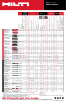
OPERATING INSTRUCTIONS
AND MAINTENANCE NOTES ON
LIQUID TRANSFORMERS
Ocrev srl
Via Oltre Agno 2 - 36070 Brogliano VI - ITALY
CONTENTS:
1. TRANSPORT
2. LIFTING
3. STORAGE
4. ACCESSORIES
5. INSTALLATION AND START-UP
6. MAINTENANCE
7. ANOMALIES
Ocrev srl
Via Oltre Agno 2 - 36070 Brogliano VI - ITALY
1. TRANSPORT
The transformer is prepared by the manufacturer ready for operation, except for cases where
some components like HV/LV cable box, cooling elements (radiators) and oil storage tanks, are
disassembled to obtain the dimensions suitable for transport.
The components, disassembled for the aforesaid reasons, must be reassembled at the
installation site, by very carefully following the instructions set out by the manufacturer.
2. LIFTING
Lifting can be done by using the appropriate eyebolts, remembering to use long enough cables
so that H (see Fig. 1) is never less than L.
Always use all the existing rings and not only some of them.
Short lifting may also be done with hydraulic jacks, by applying suitable supporting plates
under the crate.
In some cases a forklift may be used.
Fig. 1. An example of lifting
3. STORAGE
If the transformer is not installed after a reasonably short time, care must be taken. Before
applying energy, carefully clean the transformer, by removing dust and other foreign particles
and objects that may have deposited on the bushings or other parts of the cover because of the
long storage period.
Ocrev srl
Via Oltre Agno 2 - 36070 Brogliano VI - ITALY
4. ACCESSORIES
The transformer is usually fitted with the following accessories:
- bushings placed on the primary side,
- bushings placed on the secondary side,
- bi-directional rollers,
- lifting lugs,
- off-load tap changer for adjusting the transformer ratio,
- thermometer pockets,
- oil conservator (*),
- oil level indicator,
- Buchholz relay (*),
- silicagel breather (*),
- oil filling hole and plug (*),
- oil drain valve,
- earthing terminals,
- rating plate.
(*) only for breathing type
Depending on the client’s requests the transformer may be fitted with particular accessories,
each of which supplied with its specific description of operation attached to the accessory
itself.
5. INSTALLATION AND START-UP
If not otherwise requested, the characteristics indicated on the rating plate of the transformer
refer to installations of up to a maximum height of 1.000 m above sea level.
For correct thermal dispersal of the leaks, due to self-consumption of the transformer, there
must be a minimum distance of 30 cm from the wall, between the cooling surfaces and the
room walls, and 60 cm between one transformer and another, if there are more than one.
The room must be dimensioned to permit air circulation of 4÷5 m3/min. for each kW of
losses. If this condition is not met there would be an anomalous increase in temperature
compared to that calculated.
A normal environment may be considered as one where the temperature comes within the
following values:
* minimum temperature
-25°C
* average annual temperature
20°C
* average daily temperature
30°C
* maximum temperature
40°C
Temperatures differing from those indicated will have to be studied to establish the causes.
Ocrev srl
Via Oltre Agno 2 - 36070 Brogliano VI - ITALY
1) After the HV/LV cables have been connected, carried out by keeping count of the
respective phase sequence, make sure, before applying energy, that the tap-changer is set to
the desired transformer ratio;
2) Make sure that the silicagel breather has been mounted according to the following
modalities:
- remove the hexagon plug
- let any oil that has entered into the pipe during transport drip out
- screw up the silicagel breather
(be careful not to open the drain plug of the oil conservator);
3) Check that the oil level in the oil conservator is set to 20°C;
4) For parallel operation with other transformers, the transformer must respect the following
conditions:
a) It must belong to the same vector group as the transformers to be used in parallel,
according to the following table:
Three-phase transformer connections
0
1
5
6
11
2
4
7
8
10
Yy0
Yd1
Yd5
Yy6
Yd11
Dd0
Dy1
Dy5
Dd6
Dy11
Dz0
Yz1
Yz5
Dz6
Yz11
Yd7
Dd2
Dd4
Dy7
Dd8
Dd10
Dz2
Dz4
Yz7
Dz8
Dz10
b) Identical value of ‘Short-Circuit Current’, with only the tolerance foreseen by the
Standards, of the other transformers meant for parallel connection.
Ocrev srl
Via Oltre Agno 2 - 36070 Brogliano VI - ITALY
6. MAINTENANCE
Generally the transformer needs no particular expedients for maintenance. However, to
ensure safe and reliable operation, it is best to check periodically, the frequency of which
depends on the environmental and operation conditions:
a) Check the oil level
b) Check the oil temperature, which must never exceed environmental temperature by
60°C, considering an environmental temperature of 40°C
c) After about a year’s operation it is advisable to take a sample of oil and make it
undergo a dielectric test.
The sample must be taken from the discharge valve at the bottom of the transformer,
unless it is fitted with a special sampling valve.
d) General cleaning from dust and other dirt that may have collected there, paying
special attention to the bushings
e) Check the sealing capacity of the gaskets
*** THE ABOVE-MENTIONED OPERATIONS MUST BE CARRIED OUT WITH
THE TRANSFORMER CONNECTED TO GROUND AND NOT ENERGISED ***
7. ANOMALIES
ANOMALY
High noise level
Overheating
CAUSE
Undistributed load
Overloading
Insufficient air circulation
Ocrev srl
Via Oltre Agno 2 - 36070 Brogliano VI - ITALY
SOLUTION
Contact the manufacturer
Take the load back to the
nominal values
Check that the values found
under the chapter “Installation
and Start-up ”