1
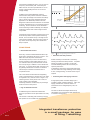
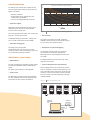
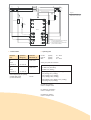
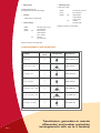
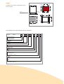
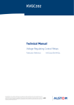
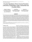
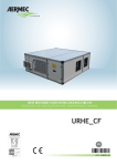
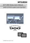
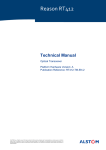
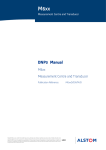
P R OT E C T I O N
KBCH 120, 130, 140
Differential Protection for Transformers
and Generators
Type KBCH relays offer biased differential current,
restricted earth fault and overfluxing protection
primarily for the protection of two or three winding
power transformers, auto transformers or
generator-transformer units. The KBCH provides
these features in a very compact and space –
efficient case size, for ease of installation.
All models are three phase units with internal
vector group compensation and line current
transformer ratio correction, thus eliminating the
need for interposing transformers.
Figure 1
KBCH relay
Up to four biased current inputs per phase can
be provided to cater for power transformers with
more than two windings and/or more than one
circuit breaker controlling each winding, as in
mesh or one-and-a-half circuit-breaker busbar
arrangements. Versions are available that can
accommodate a mixture of 1A (HV) and 5A (LV)
CTs, as well as standard models having all 1A or
all 5A CTs.
MODELS AVAILABLE
> KBCH120
offers 2 bias inputs per phase for the protection of a two-winding power
transformer.
Customer Benefits
• Biased differential
protection
• Restricted earth fault
protection
• Overfluxing protection
• Integral CT ratio and
vector group
compensation
• Measurement of phase,
differential and bias
currents
AREVA T&D
> KBCH130
offers 3 bias inputs per phase for the protection of a three-winding power
transformer or a two-winding power transformer with 2 sets of CTs on one
winding.
> KBCH140
offers 4 bias inputs per phase.
All models are available with either 1A or 5A inputs on
the primary and secondary side. Alternatively the
KBCH 120 and 140 can be provided with 1A CTs on
the high voltage windings and 5A CTs on the low
voltage windings.
3
2
Operate
Differential current (xIn)=
pe
I1 + I1 + I3 + I4
In addition to the biased differential protection,
restricted earth fault protection has been included to
cover a larger percentage of the transformer windings.
Figure 7 shows some typical restricted earth fault
applications. The differential protection has been
designed to restrain when the transformer is overfluxed
so that an instantaneous trip is not issued for transient
overfluxing. Since a transformer cannot withstand a
severe overfluxing condition indefinitely, time delayed
overfluxing protection and an alarm stage has been
incorporated.
Contacts that monitor the status of external plant, such
as Buchholz protection and temperature measuring
devices, can be connected to any of the eight control
inputs that are available. Each input can be routed to
any number of the output relays via a variable time
delay if required.
0%
Restrain
8
1
Setting range
0.1 - 0.5In
slo
able
Allow tio error
ra
20%
20%
0
slope
1
2
3
Figure 2
Biased differential characteristic
A
B
C
FUNCTIONS
> Biased differential element
Figure 3
Each relay, contains a biased differential element per
phase with a characteristic as shown in Figure 2. The
KBCH has a dual slope bias characteristic.
The initial slope of 20%, from zero to rated current,
ensures sensitivity to faults whilst allowing for up to
15% mismatch when the power transformer is at the
limit of its tap range, in addition to current transformer
ratio errors. At currents above rated, extra errors may
be gradually introduced as a result of CT saturation.
The bias slope is therefore increased to 80% to
compensate for this.
The current waveform associated with magnetising
inrush is characterised by a period of each cycle where
its magnitude is very small, as shown in Figure 3. By
measuring the time of this period of low current, an
inrush condition can be identified.
Overfluxing restraint is conditioned by the percentage
of fifth harmonic current present.
> High set differential element
An additional high set instantaneous differential
element is provided to ensure rapid clearance of heavy
faults.
This element is essentially peak measuring to ensure
fast operation for internal faults with saturated CTs.
2>3
4
| I1 | + | I2 | + | I3 | + | I4 |
Effective Bias (xIn)=
2
Typical magnetising inrush waveforms
> Restricted earth fault protection
Greater sensitivity for earth faults is obtained by
including restricted earth fault protection. A separate
element per winding is provided. An externally
mounted stabilising resistor will be necessary for
optimum performance.
In applications where heavy internal earth fault levels
can occur and where a high stabilising resistor setting
is used, a voltage limiting, non-linear resistor may be
required.
> Overfluxing Alarm and Tripping Protection
A single phase-phase connected voltage input is
provided to enable overfluxing detection. Alarm and
tripping characteristics, which are based on a
measurement of the voltage/frequency ratio, are
provided.
The alarm is definite time delayed whilst the trip
characteristic may be selected as either definite time,
or an IDMT curve (Figure 4).
Integrated transformer protection
in a small package, for ease
of fitting / retrofitting.
CONFIGURATION
Operating time as a function of the actual excitation and the set
starting value for different time multiplier settings (K)
time (s)
The setting of logic function links, together with the
input and output masks, define the way the relay will
operate. This allows:
1000
100
• Selection of features
K=6
• Implementation of user defined logic using
auxiliary timers (8 available)
• Control of the integral disturbance recorder.
K=4
K=2
10
K=5
> Inputs and outputs
K=1
1
1
KBCH has 8 optically isolated inputs which may be
reassigned by the user with any of the available
functions from the setting menu.
There are 8 programmable outputs, each comprising a
relay with 1 normally open contact.
A dedicated watchdog contact with 1 normally open
and 1 normally closed contact is also available.
> Alternative setting group
Two setting groups are provided.
This allows the user to set one group to normal
operating conditions while a second group may be set
to cover alternative operating conditions.
ANCILLARY FUNCTIONS
> Measurements
The relay can display the magnitude of phase currents
for each input, differential current and average bias
current.
The power system frequency is also displayed.
> Fault records
The fault flags for the last five faults are recorded by
the relay. Additional records of the magnitude of the
fault currents are also stored for the last fault.
1.1
1.2
1.3
M=
Figure 4
1.4
1.5
(V/f)
(V/f) setting
Inverse time characteristic for overfluxing protection
> Event records
Fifty events can be stored in a buffer. Software is
available to allow the events to be accessed remotely
by a PC via the communications system.
> Disturbance records (Oscillography)
The analogue channels record up to nine phase
currents (three per transformer winding) three
differential currents, three average bias currents and
the voltage.
The digital channels record the status of the output
relays and control inputs.
> Power-on diagnostics and self monitoring
Power-on diagnostic tests are carried out by the relay
when it is energised. Continuous self-monitoring, in the
form of watchdog circuitry and memory checks are also
performed. In the event of a failure, the relay will either
lock out or attempt a recovery, depending on the type
of failure detected.
Figure 5
Basic communication system
Relay 32
Relay 4
Desktop
computer
PC
Relay 3
Relay 2
Relay 1
Protocol
converter
KITZ
IEC870-5
RS232
K-Bus
RS485
1.6
USER INTERFACE
> Relay interconnection
The relays can be interconnected via a shielded,
twisted wire pair known as K-Bus.
The K-Bus is connected through a protocol converter
known as KITZ, either directly or via a modem, to the
RS-232 port of the PC.
This system allows up to 32 relays to be accessed
through one RS-232 communications port (Figure 5).
> Front panel user interface
The features of the relay can be accessed through a
menu-driven system.
The user can move around the menu by means of the
keys on the relay frontplate. This can be done with the
cover in place, but any change to the settings requires
the cover to be removed.
> Password protection
> Remote access user interface
The menu table can also be accessed via the remote
communications facility. This allows all of the menu
cells in a column to be displayed simultaneously on the
screen of a PC.
Password protection is provided on settings which alter
the configuration of the relay, any accidental change to
which could seriously affect the ability of the relay to
perform its intended function.
Figure 6
P1
A
Typical application diagram KBCH120
P2
S1
B
P2
S2
HV
P1
S2
LV
C
S1
A
B
C
63
69
64
65
70
71
66
67
72
73
68
74
75
KBCH 120
21
76
77
22
23
78
79
24
25
80
81
26
27
82
83
28
84
4
HV lo> (see Figure 10)
A
B
A
C
A
B
C
C
B
Phase rotation
AC/DC
supply
Vx
LV1 lo> (see Figure 10)
WD
13
b
RL2
18
4
29
RL4
6
31
32
8
33
34
9
10
35
36
37
38
39
40
41
42
43
44
45
46
Logic input common (1)
47
48
Initiate aux. timer 3 L3
49
50
51
52
53
54
55
56
66
67
68
69
70
71
72
73
74
75
76
77
78
21
22
79
80
23
24
81
82
25
26
83
84
27
28
13
14
17
18
19
20
SCN
36
Trip
Id > A,B,C Id >> A,B,C
Io > HV,LV1,LV2 V/f trip
Initiate aux. timer 1 L1
46
48
RL5
Initiate aux. timer 4 L4
Initiate aux. timer 5 L5
See Note 4
Initiate aux. timer 6 L6
Initiate aux. timer 7 L7
Logic input common (2)
44
Trip
Id > A,B,C Id >> A,B,C
Io > HV,LV1,LV2 V/f trip
Trip
31
Id > A,B,C Id >> A,B,C
Io > HV,LV1,LV2 V/f trip
Tap up
35
Tap down
37
RL6
Initiate aux. timer 2 L2
40
33
Initiate aux. timer 0 L0
Module terminal blocks
viewed from rear
Id > A,B,C Id >> A,B,C
Io > HV,LV1,LV2 V/f trip
29
30
7
65
Trip
42
RL3
1
5
Relay failed
38
c
17
3
32
34
RL1
a
64
Relay healthy
30
RL0
n
63
5
WD
N
57
6
3
14
50
39
Alarm = V/f alarm
41
RL7
52
43
Trip
Id > A,B,C Id >> A,B,C
Io > HV,LV1,LV2 V/f trip
57
45
47
1
Case earth connection
49
54
51
53
56
See Note 4
K-Bus communications port
SCN
7
55
8
+48V field voltage
Notes:
1. (a)
4>5
CT shorting links make
before (b) and (c) disconnect.
2. VT input must be supplied with phase - phase voltage.
Connections are typical only.
(b)
Short terminals break before (c).
3. Earth connections are typical only.
(c)
Long terminals.
4. SCN = Screen connection for K-Bus.
(d)
Pin terminal (PCB type)
KBCH : Quick to configure, simple to test
A
B
P1
P2
S1
P2
S2
P1
S2
S1
C
A
B
C
P2
P1
S2
Figure 7
S1
See
Note 2
See Note 1
63
69
64
65
70
71
RS
See
Note 2
66
67
72
73
68
RS
See
Note 1
74
75
KBCH 120
21
76
77
22
23
78
79
24
25
80
81
26
27
82
83
Notes:
1. See Service Manual R8530 for the setting of
the external stabilising resistor.
28
84
2. Optional voltage limiting non-linear resistor
(see Service Manual R8530).
> Operating time
> Technical Data
Nominal
(Vx)
Operative
Range (V)
24–125V dc
or
110V
50/60Hz ac
20–150V dc
48–250V dc
or
220V
50/60Hz ac
33–300V dc
Absolute
Maximum (V)
low set
high set
REF
typically
typically
typically
30 – 35ms
15ms
20 – 40ms
190V crest
Vector group and ratio correction
50–133V ac
HV Ratio Cor (primary)
380V crest
LV1 Ratio Cor (secondary)
LV2 Ratio Cor (tertiary)
87–265V ac
Field voltage supply for optically
isolated digital inputs
(current limit: 60mA)
48V dc
Yy0 (0deg), Yd1 (–30deg), Yd2 (–60deg),
Yd3 (–90deg), Yd4 (–120deg),
Yd5 (–150deg), Yy6 (+180deg),
Yd7 (+150deg), Yd8 (+120deg),
Yd9 (+90deg), Yd10 (+60deg), Yd11 (+30deg),
Ydy0 (0deg), Ydy6 (+180deg),
HV Ratio Cor (primary)
0.05 to 2 in steps of 0.01
LV1 Ratio Cor (secondary)
0.05 to 2 in steps of 0.01
LV2 Ratio Cor (tertiary)
0.05 to 2 in steps of 0.01
Typical restricted
earth fault connections
> Watchdog relays
> Digital Inputs
1 make and 1 break
Optically isolated inputs
8 energised from the 48V field voltage
• Make:
10A and carry for 0.2s
• Carry:
> Contacts
• Break:
5A continuous
DC
• Output relays 8 single make
AC
> Contact ratings
• Make:
30A and carry for 0.2s
• Carry:
5A continuous
• Break:
DC
AC
30W resistive
15W inductive
(L/R = 0.04s)
1250VA
(5A maximum)
Subject to maxima of 5A and 300V
50W resistive
25W inductive
(L/R = 0.04s)
1250VA
(5A maximum)
Subject to maxima of 5A and 300V
TRANSFORMER CONFIGURATION
Setting
No. of bias
inputs
Configuration
Applicable to:
HV
HV + LV
2
KBCH120/130/140
LV
HV
HV + LV1 + LV2
3
KBCH130/140
LV2
LV1
HV
HV (x2) + LV
3
KBCH130/140**
LV
HV
HV + LV (x2)
3
KBCH130/140
LV
HV
HV (x2) + LV1 + LV2
4
Only KBCH140
LV2
LV1
HV
HV + LV1 (x2) + LV2
4
LV1
LV2
Only KBCH140**
HV
HV (x2) + LV (x2)
4
Only KBCH140
LV
6>7
Transformer, generator or reactor
differential, and busbar protection
(arrangements with up to 4 feeders)
CASE
4 holes ø4.4
200
The KBCH unit is housed in a size 8 Midos case as
shown in Figure 8.
155.4
24
168
Figure 8
Push button
projection 10 max
Case outline size 8
159
203
Panel cut-out:
Flush mounting fixing details
32
212
25 min.
177
157 max.
Reset
206
Flush mounting
All dimensions in mm
INFORMATION REQUIRED WITH ORDER
Unit type
KBCH1
2 bias inputs per phase
3 bias inputs per phase
4 bias inputs per phase
Configuration:
Standard
Case Size:
Size 8 Midos flush mounting
Auxiliary voltage:
24/125V
48/250V
Rating:
Vn = 100/120V In = 1A
Vn = 100/120V In = 5A
* Vn = 100/120V In = 1A/5A
Language:
English
French
German
Spanish
* Not available for KBCH 130.
0
2
3
4
0
1
W
1
2
5
L
M
P
E
F
G
S
11
AREVA TRACK RECORD TRANSFORMER DIFFERENTIAL PROTECTION
>> Over 34 000 predecessor MBCH
relays shipped.
>> Over 10 500 KBCH differential
relays delivered since launch in 1994.
>> MiCOM P63x series available for fully integrated transformer
protection, with extra overcurrent
protection and Programmable Logic (PSL).
>> KVGC 202 available for voltage
AUTOMATION-L3-KBCH-BR-04.05-0910-GB - ©2005 AREVA - AREVA, the AREVA logo and any alternative version thereof are trademarks and service marks of AREVA.
MiCOM is a registered trademark of AREVA. All trade names or trademarks mentioned herein whether registered or not, are the property of their owners. - 389191982 RCS PARIS - Printed in France - SONOVISION-ITEP
regulation (tap change control).
AREVA T&D Worldwide Contact Centre:
http://www.areva-td.com/contactcentre/
Tel.: +44 (0) 1785 250 070
www.areva-td.com
www.areva-td.com/protectionrelays
Our policy is one of continuous development. Accordingly the
design of our products may change at any time. Whilst every
effort is made to produce up to date literature, this brochure
should only be regarded as a guide and is intended for
information purposes only. Its contents do not constitute an offer
for sale or advise on the application of any product referred to in
it. We cannot be held responsible for any reliance on any
decisions taken on its contents without specific advice.