1
Operating Instructions
ENGLISH
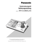
System Controller
WV-CU550CJ
DEUTSCH
Model No.
ALA
RM
BUS
A
RESCK
ET
1
BA
SEQCK FO
R
SEQWARD
ALT
F1
AUX
F2
1
2
D
-1C EC
AM
IN
+1C C
AM
4
STO
P
7
ESC
F3
2
5
8
MO
N
SLO
W
FRANÇAIS
Y
F4
3
6
RES
ET
CLO IRIS
SE
OP
EN
9
0
AF
CAM
ZO
TEL OM
E
SET
FO
NEACUS
R
WID
E
FAR
tem
Co
ntro
ller
WV
-CU
550
CJ
Before attempting to connect or operate this product,
please read these instructions carefully and save this manual for future use.
ESPAÑOL
Sys
ENGLISH VERSION
CAUTION:
Before attempting to connect or operate this product, please read the label on the bottom.
CAUTION
RISK OF ELECTRIC SHOCK
DO NOT OPEN
For U.K.
FOR YOUR SAFETY PLEASE READ THE FOLLOWING TEXT CAREFULLY.
This appliance is supplied with a moulded three pin mains plug for your
safety and convenience.
A 13 amp fuse is fitted in this plug.
Should the fuse need to be replaced please ensure that the replacement
fuse has a rating of 13 amp and that it is approved by ASTA or BSI to
BS1362.
or the BSI mark
on the body of the
Check for the ASTA mark
fuse.
If the plug contains a removable fuse cover you must ensure that it is
refitted when the fuse is replaced.
If you lose the fuse cover the plug must not be used until a replacement
cover is obtained.
A replacement fuse cover can be purchased from your local Panasonic
Dealer.
H
CAUTION: TO REDUCE THE RISK OF ELECTRIC SHOCK,
DO NOT REMOVE COVER (OR BACK).
NO USER-SERVICEABLE PARTS INSIDE.
REFER SERVICING TO QUALIFIED SERVICE PERSONNEL.
The lightning flash with arrowhead symbol,
within an equilateral triangle, is intended to
alert the user to the presence of uninsulated
"dangerous voltage" within the product's
enclosure that may be of sufficient magnitude to constitute a risk of electric shock to
persons.
The exclamation point within an equilateral
triangle is intended to alert the user to the
presence of important operating and maintenance (servicing) instructions in the literature accompanying the appliance.
The serial number of this product may be found on the bottom of the unit.
You should note the serial number of this unit in the space
provided and retain this book as a permanent record of your
purchase to aid identification in the event of theft.
Model No.
IF THE FITTED MOULDED PLUG IS UNSUITABLE FOR THE SOCKET OUTLET IN YOUR HOME THEN THE FUSE SHOULD BE
REMOVED AND THE PLUG CUT OFF AND DISPOSED OF SAFELY.
THERE IS A DANGER OF SEVERE ELECTRICAL SHOCK IF THE
CUT OFF PLUG IS INSERTED INTO ANY 13 AMP SOCKET.
If a new plug is to be fitted please observe the wiring code as shown
below.
If in any doubt please consult a qualified electrician.
WARNING: This apparatus must be earthed.
IMPORTANT
The wires in this mains lead are coloured in accordance with the following code.
Green-and-yellow:
Earth
Blue:
Neutral
Brown:
Live
As the colours of the wire in the mains lead of this appliance may not
correspond with the coloured markings identifying the terminals in your
plug, proceed as follows.
The wire which is coloured green-and-yellow must be connected to
the terminal in the plug which is marked with the letter E or by the earth
symbol I or coloured green or green-and-yellow.
The wire which is coloured blue must be connected to the terminal in
the plug which is marked with the letter N or coloured black.
The wire which is coloured brown must be connected to the terminal
in the plug which is marked with the letter L or coloured red.
How to replace the fuse
Open the fuse compartment with
a screwdriver and replace the fuse
and fuse cover.
WV-CU550CJ
Serial No.
WARNING:
To reduce the risk of fire or electric shock, do not expose this appliance to rain or moisture.
2
G
FUSE
PREFACE ...................................................................................................................................................................................... 4
FEATURES .................................................................................................................................................................................... 4
PRECAUTIONS ............................................................................................................................................................................. 5
MAJOR OPERATING CONTROLS AND THEIR FUNCTIONS ...................................................................................................... 6
INSTALLATION ............................................................................................................................................................................. 9
SYSTEM INFORMATION .............................................................................................................................................................. 10
SPECIFICATIONS ......................................................................................................................................................................... 11
STANDARD ACCESSORIES ......................................................................................................................................................... 11
MAJOR OPTIONAL UNITS AND ACCESSORIES ......................................................................................................................... 11
3
We declare under our sole responsibility that the product to which
this declaration relates is in conformity with the standards or other
normative documents following the provisions of Directives
EEC/73/23 and EEC/89/336.
Vi deklarerar härmed värt fulla ansvar för att den produkt till vilken
denna deklaration hänvisar är i överensstämmelse med standarddokument, eller andra normativa dokument som framställs i EECdirektiv nr. 73/23 och 89/336.
Wij verklaren als enige aansprakelijke, dat het product waarop deze
verklaring betrekking heeft, voldoet aan de volgende normen of
andere normatieve documenten, overeenkomstig de bepalingen
van Richtlijnen 73/23/EEC en 89/336/EEC.
Ilmoitamme yksinomaisella vastuullamme, että tuote, jota tämä
ilmoitus koskee, noudattaa seuraavia standardeja tai muita ohjeellisia asiakirjoja, jotka noudattavat direktiivien 73/23/EEC ja
89/336/EE. säädöksiä.
Vi erklærer os eneansvarlige for, at dette produkt, som denne
deklaration omhandler, er i overensstemmelse med standarder eller
andre normative dokumenter i følge bestemmelserne i direktivene
73/23/EEC og 89/336/EEC.
Vi erklærer oss alene ansvarlige for at produktet som denne
erklæringen gjelder for, er i overensstemmelse med følgende
normer eller andre normgivende dokumenter som følger bestemmelsene i direktivene 73/23/EEC og 89/336/EEC.
ENGLISH
CONTENTS
PREFACE
The WV-CU550CJ System Controller, when combined with the optional WJ-SX550C Matrix Switcher and WJ-AD550 Extension
Unit, allows for flexible control of 128 cameras and 16 monitors.
When used in a system with either Receivers (WV-RC100, WV-RC150 or WV-RC170) or with Panasonic’s Combination cameras, the WV-CU550CJ can control camera functions such as zoom and focus and can also control accessory equipment such
as Pan/Tilt Heads.
In addition, the WV-CU550CJ can control sequential switching in systems programmed from the Set Up Menu of the WJSX550C Matrix Switcher.
FEATURES
The WV-CU550CJ System Controller, when combined with the WJ-SX550C Matrix Switcher and WJ-AD550 Extension Unit,
enables control of the following functions:
• Routing of up to 128 cameras to any one of 16 monitors
• Remote control of up to 128 cameras and auxiliary equipment by using optional receivers and accessories, including:
1. Remote control of Pan-Tilt Head and Camera Housing
2. Remote control of Motorized Zoom Lenses: Focus, Zoom and Iris
3. Remote control of camera settings, including Electronic Sensitivity Enhancement, Electronic Shutter, Electronic Zoom,
and more
• Selection of various sequence functions such as Program Sequence, Tour Sequence and Group Sequence
Additional features of the WV-CU550CJ include:
• Up to 8 WV-CU550CJ System Controllers can be connected in a system by using standard RS-485 shielded 4-wire twisted
pair cable. Can also be combined with standard communication media such as modems, fiber optics and microwave.
• Ergonomic design reduces the number of switches to only those with common functions. Secondary functions are
accessed through function keys.
• Single-handed control of pan/tilt, zoom, and auto focus functions
4
PRECAUTIONS
• Refer all work related to the installation of this
product to qualified service personnel or system
installers.
• Do not attempt to disassemble the appliance.
To prevent electric shock, do not remove screws or
covers.
There are no user-serviceable parts inside. Contact
qualified service personnel for maintenance.
• Handle the appliance with care.
Do not strike or shake it, as this may damage the appliance.
• Do not expose the appliance to water or moisture,
nor try to operate it in wet areas.
Take immediate action if the appliance becomes wet.
Turn the power off and refer servicing to qualified service personnel. Moisture may damage the appliance
and also cause electric shock.
5
• Do not use strong or abrasive detergents when
cleaning the appliance body.
Use a dry cloth to clean the appliance when it is dirty.
When the dirt is hard to remove, use a mild detergent
and wipe gently.
• Do not operate the appliance beyond its specified
temperature, humidity or power source ratings.
Use the appliance at temperatures within –10 °C to
+50 °C (14 °F to 122 °F) and a humidity below 90 %.
The input power source for this appliance is 220 V to
240 V AC 50 Hz.
MAJOR OPERATING CONTROLS AND THEIR FUNCTIONS
■ Front View
q
w
e
ALARM
BUSY
r
t
y
F1
@0
@1
ACK
RESET
BACK FORWARD
SEQ SEQ ALT
@3
F2
F3
1
2
3
4
5
6
u
F4
PRESET
IRIS
CLOSE OPEN
AF
@2
AUX
1
2
DEC
INC
-1CAM +1CAM STOP
SLOW
7
8
9
MON
0
CAM
ESC
SET
ZOOM
TELE
FOCUS
NEAR
WIDE
FAR
System Controller WV-CU
!9
!8 !7 !6
!5
!4
!3 !2 !1
!0
o
550 CJ
i
■ Rear View
TERM.
@4
6
OFF
@5
CONTROLLER
MODE
901
ON
23
ON
CONTROLLER
UNIT No.
1-8
78
OUT
OFF
456
DATA
IN
@6
@7
@8
@9
q Alarm Indicator (ALARM)
Blinks to indicate that an alarm condition exists.
It changes to steady light when the alarm is reset automatically.
To turn the indicator off, press the ACK RESET button.
w Busy Indicator (BUSY)
Lights up when you attempt to control a monitor or a
camera that is already used by a higher priority operator, or when the higher priority operator selects the
monitor or camera you are currently operating.
Operations from the System Controller are disabled
until this indicator goes off.
e Function Buttons (F1/F2/F3/F4)
Select functions displayed on the LCD (Liquid Crystal
Display) display.
r LCD (Liquid Crystal Display) Display
Displays function menus, numeric input, and system
status.
t Direction Buttons (A, B, D, C)
Select a function menu for display on the LCD display.
y Zoom Wheel Controller
This control is used for zooming cameras equipped
with the specified lens. Moving the control to the right
will zoom in the image. Moving the control to the left will
zoom out the image.
u Joystick Controller (UP/DOWN/LEFT/RIGHT)
The joystick is used to manually operate the Pan/Tilt
Head, or move the cursor in the Matrix Switcher’s Setup
Menu on the active monitor screen.
i Top Button
Pressing this button will automatically set the lens focus
of a specified camera.
o Iris Control Buttons (IRIS CLOSE, OPEN)
Close or open the lens iris of cameras equipped with
the specified lens.
When these buttons are pressed at the sometime for 3
seconds or more, the lens iris is reset to the factory
default setting.
!0 Focus Control (FOCUS NEAR/FAR)
Adjust the lens focus of cameras equipped with the
specified lens.
!1 Zoom Control (ZOOM TELE/WIDE)
This control is used for zooming cameras equipped
with the specified lens.
7
!2 Preset Button (PRESET)
Auto Focus Button (AF)
PRESET: This button, in combination with the Numeric
keys, is used to move the selected camera to a preset position in a system equipped with the specified
cameras.
AF: Pressing this button will automatically set the lens
focus of a specified camera.
!3 Camera (Set) Key [CAM (SET)]
CAM: Used for camera selection. To select a camera,
enter the desired camera number with the Numeric
keys, and then press the CAM key.
SET: This key, in combination with the Numeric keys, is
used to enter numeric input, such as operator ID
and password.
It is also used to execute the currently highlighted
selection and to enter a submenu in the Setup
Menu of the Matrix Switcher.
!4 Numeric Keys (0 to 9)
These keys are used for numeric input into the system,
such as the camera and monitor number, sequence
number, preset position, etc.
!5 Monitor (Escape) Key [MON (ESC)]
MON: This key is used to select a monitor.
To select a monitor, press the corresponding
Numeric keys, followed by the MON key.
ESC: This key is used to escape from the currently
highlighted selection on the Setup Menu of the
Matrix Switcher.
Pressing this key, while the Alternate (ALT) indicator is
on, will display the video that is connected to the
Monitor Input (MONITOR IN) Connector on the WVPB5504AE Video Output Board.
!6 Stop/Slow Button (STOP/SLOW)
STOP: Pauses a sequence that is being run on the
active monitor.
SLOW: For fine pan/tilt control, move the joystick while
holding down the SLOW button.
!7 Increment Button (INC +1CAM)
When a sequence running in forward direction has
been paused with the STOP button, pressing this button
will move the sequence one frame to the next step (in
forward run direction). If the sequence was running in
reverse direction, the button will move the sequence
one frame to the next step (in reverse run direction).
This button is also used to select a camera. Pressing
this button will replace the currently selected camera
with the next higher camera number, if the active monitor is in Spot mode.
!8 Decrement Button (DEC –1CAM)
When a sequence running in forward direction has
been paused with the STOP button, pressing this button
will move the sequence one frame to the previous step
(in forward run direction). If the sequence was running
in reverse direction, the button will move the sequence
one frame to the previous step (in reverse run direction).
This button is also used to select a camera. Pressing
this button will replace the currently selected camera
with the next lower camera number, if the active monitor
is in Spot mode.
!9 Auxiliary Button (AUX 1, 2)
These buttons toggle the auxiliary switches in the
Receiver on and off.
The auxiliary switches can be used, for example, to
activate equipment connected to the receiver, such as
lamps and buzzers.
@7 Mode Selection Switch (MODE)
These switches are used to set the mode of the System
Controller connected to the Matrix Switcher. Set the
switches as shown below.
MODE
Normal Mode
ON 1
2
3
4
MODE
CAM-P Mode
ON 1
2
3
4
@8 Controller On/Off Switch (CONTROLLER ON/OFF)
This switch is used to turn the WV-CU550CJ system
controller power on and off.
@9 Power Cord
@0 Alternate Button (ALT)
This button activates the alternate function of dual-function control buttons.
@1 Forward Sequence Button (FORWARD SEQ)
This button is used to run a selected Program or Tour
Sequence in forward direction on the active monitor.
It also restarts a sequence forward from the step that
was previously paused by pressing the Stop button.
@2 Backward Sequence Button (BACK SEQ)
This button is used to restart a sequence backward
from the step that was previously paused by pressing
the Stop button.
@3 Alarm Acknowledge and Reset Button (ACK RESET)
This button cancels an activated alarm. To cancel an
alarm, first select the alarmed monitor(s), then press the
ACK RESET button once for alarm acknowledgment
(the indicator on the button blinks rapidly), and finally
press it again for alarm reset (the indicator goes off).
After an alarm acknowledgment, pressing this button
while the Alternate (ALT) indicator is on will cancel all
currently activated alarms at the same time.
@4 Data Ports (DATA IN, OUT)
Exchanges control data with the WJ-SX550C Matrix
Switcher in a system.
@5 Termination Switch (TERM ON/OFF)
This switch enables termination of the controller’s data
port.
@6 Controller Unit Number Switch (CONTROLLER UNIT
NO.)
This switch is used to identify the unit number of the
System Controller in multiple system controller applications. Up to eight controllers can be installed in a system.
8
NOTE
Refer to the Operating Instructions of the WJ-SX550C
Matrix Switcher for further details.
INSTALLATION
■ System Controller for the WJ-FS616 Series Video Multiplexer
When combined this System Controller with the optional WJ-FS616 Series Video Multiplexer, place the display sheets and label
on the controller shown below.
Refer to the Operating Instructions of WJ-FS616 Series for further details.
ALAR
M
BUSY
AC
RES K
ET
BA
SEQCK FO
RW
SEQ ARD
ALT
1
F1
AUX
D
-1C EC
AM
F2
1
2
IN
+1C C
AM
4
STO
P
7
ESC
5
8
MO
N
SLO
W
F3
2
F4
3
6
RES
ET
CLO IRIS
SE
OP
EN
9
0
AF
CAM
ZO
TELEOM
SET
FO
NEACUS
R
WID
E
FAR
Sys
tem
Co
ntro
Note: Locate the System Controller in a level place.
9
ller
WV
-CU
550
CJ
SYSTEM INFORMATION
Please note that the following functions were added to
improve the operation of the combination cameras.
■ Version Information
● WJ-SX550 Series Matrix Switcher
The onscreen display indicates the version in “Cold Start”
or “Normal Start” during the power up procedure.
■ Additions
● Selection of Pan/Tilt Speed
Matrix
The Pan/Tilt speed can be changed by selecting a mode in
the menu (A1) displayed on the LCD display of the controller.
1. Select the desired monitor and camera.
Camera cc
Monitor mm
SLW
F1
F3
F2
A1
FST
Model
Switcher
WJ-SX550C
"Normal
CPU
U
V
C
V
n
i
h
D
Start"
Board
i
d
a
/
SW.
Position
t No.
eo
racter Type
VS
F4
ROM
2. Select a mode by pressing the F3 or F4 button.
“❑” indicates the currently selected mode.
SLW: Moves the Pan/Tilt Head at lower speed.
FST: Moves the Pan/Tilt Head at higher speed.
C
C
A
O
R
P
o
l
u
S
U
n
a
t
-
Ver.
t
r
p
4
rol
m
ut
85
No.1
No.1
No.1
3. Move the Joystick to move the Pan/Tilt Head in the
desired direction.
Note: Changing the Pan/Tilt speed by pressing the
STOP/SLOW button is enabled only when FST
mode is selected.
The above function is available in a system that includes
the following equipment:
WJ-SX550 Series Matrix Switcher
CPU
Ver. 6.00 or later
Control Ver. 6.00 or later
WV-PB5548E
Data Board
Ver. 6.00 or later
10
01
PAL
1
VS
Note: x.xx is a version number.
X
X
X
X
X
.
.
.
.
.
X
X
X
X
X
X
X
X
X
X
SPECIFICATIONS
Power Supply:
Power Consumption:
Data Input/Output:
Switching Functions:
Camera Functions:
Lens Functions:
Housing:
Pan/Tilt:
Auxiliary Switch:
Unit Number:
Ambient Operating Temperature:
Ambient Operating Humidity:
Dimensions:
Weight:
220 V to 240 V, AC 50 Hz
Approx. 5 W
6-conductor Modular Jack (RS-485, 4-wire)
Program Sequence/Tour Sequence
Group Sequence/Backward Sequence
Forward Sequence/Inc Dec
Electronic Shutter: On/Off, Shutter Speed Select
Electronic Sensitivity Up Mode Select: Auto/Manual/Off
Electronic Zoom: On/Off, Zoom Position: Area Select
Back Light Compensation: Auto/Preset/Off
Iris: Open/Close/Preset (only with DC control lens)
Focus: Near/Far
Zoom: Tele/Wide
Auto Focus: Activate
Wiper: On/Off, Defroster: On/Off, Camera: On/Off
Manual Pan: Right/Left, Manual Tilt: Up/Down
Auto Pan: On/Off, Random Pan: On/Off, Preset, Home
AUX 1 and 2: On/Off
1 to 8
–10 °C to +50 °C (14 °F to 122 °F)
Less than 90 %
370 mm (W) x 129 mm (H) x 221 mm (D)
[14-9/16” (W) x 5-1/8” (H) x 8-11/16” (D)]
2.2 kg (4.8 lbs.)
Weight and dimensions indicated are approximate.
Specifications are subject to change without notice.
STANDARD ACCESSORIES
Data Cable 3 m (9.8 ft.) ................................................................. 1 pc.
Templates For WJ-FS616 ................................................................1 set
MAJOR OPTIONAL UNITS AND ACCESSORIES
Matrix Switcher .......................................... WJ-SX550C
Extension Unit ............................................ WJ-AD550
Video Input Board ..................................... WV-PB5508E
Video Output Board ................................... WV-PB5504AE
Alarm Input Board ..................................... WV-PB5564E
Data Board ................................................ WV-PB5548E
Blank Panel ................................................ WV-Q63E
11
Matsushita Electric Industrial Co., Ltd.
Web Site : http://www.panasonic.co.jp/global/
NM0202-0
N 19
2002
© Matsushita Communication Industrial Co., Ltd. All rights reserved.
V8QA6008AN
Printed in Japan
Gedruckt in Japan
Imprimé au Japon
Impreso en Japón