1
UP-5300VI
CODE: 00ZUP5300VIME
POS TERMINAL
MODEL
UP-5300
("V" version)
CONTENTS
1. Removing the Rear display filter . . . . . . . . . . . . . . . . . . . . . . . . . . . . . . . . . . . . . . . . . . . . . . . .1
2. Replacing the Rear display filter . . . . . . . . . . . . . . . . . . . . . . . . . . . . . . . . . . . . . . . . . . . . . . . .1
3. Removing the Top cabinet . . . . . . . . . . . . . . . . . . . . . . . . . . . . . . . . . . . . . . . . . . . . . . . . . . . . .1
4. Replacing the Top cabinet . . . . . . . . . . . . . . . . . . . . . . . . . . . . . . . . . . . . . . . . . . . . . . . . . . . . .1
5. Removing the power supply unit and AC cord . . . . . . . . . . . . . . . . . . . . . . . . . . . . . . . . . . . . . .2
6. Replacing the power supply unit and AC cord . . . . . . . . . . . . . . . . . . . . . . . . . . . . . . . . . . . . . .2
7. Removing the LCD unit . . . . . . . . . . . . . . . . . . . . . . . . . . . . . . . . . . . . . . . . . . . . . . . . . . . . . . .2
8. Replacing the LCD unit . . . . . . . . . . . . . . . . . . . . . . . . . . . . . . . . . . . . . . . . . . . . . . . . . . . . . . .3
9. PS-RAM DISK: UP-P02MB . . . . . . . . . . . . . . . . . . . . . . . . . . . . . . . . . . . . . . . . . . . . . . . . . . . .3
10. F-ROM DISK: UP-F04RB . . . . . . . . . . . . . . . . . . . . . . . . . . . . . . . . . . . . . . . . . . . . . . . . . . . . .4
11. Cautions for UP-F04RB and UP-P02MB . . . . . . . . . . . . . . . . . . . . . . . . . . . . . . . . . . . . . . . . .4
12. D-RAM disk: S.O. DIMM (Locally supplied) . . . . . . . . . . . . . . . . . . . . . . . . . . . . . . . . . . . . . . .6
13. MCR UNIT: UP-E12MR2 . . . . . . . . . . . . . . . . . . . . . . . . . . . . . . . . . . . . . . . . . . . . . . . . . . . . .7
14. Adjusting the IRQ10/11 on the ISA PWB. . . . . . . . . . . . . . . . . . . . . . . . . . . . . . . . . . . . . . . . . .7
15. RS232 & CENTRO I/F: ER-A8RS . . . . . . . . . . . . . . . . . . . . . . . . . . . . . . . . . . . . . . . . . . . . . . .7
16. REAR DISPLAY UP-I20DP . . . . . . . . . . . . . . . . . . . . . . . . . . . . . . . . . . . . . . . . . . . . . . . . . . . .8
17. POLE DISPLAY: UP-P20DP . . . . . . . . . . . . . . . . . . . . . . . . . . . . . . . . . . . . . . . . . . . . . . . . . . .8
18. DRAWER UNIT: ER-03DW/04DW/05DW . . . . . . . . . . . . . . . . . . . . . . . . . . . . . . . . . . . . . . 10
19. COM1, COM2, COM3/5, and COM4/6 Connector . . . . . . . . . . . . . . . . . . . . . . . . . . . . . . . . 11
20. BUILT-IN PRINTER: UP-T80BP . . . . . . . . . . . . . . . . . . . . . . . . . . . . . . . . . . . . . . . . . . . . . . 12
21. HDD (UNIT: HZ-F21HD) & HDD KIT: DKIT-8671RCZZ . . . . . . . . . . . . . . . . . . . . . . . . . . . . 16
22. FDD UNIT: UP-H14FD . . . . . . . . . . . . . . . . . . . . . . . . . . . . . . . . . . . . . . . . . . . . . . . . . . . . . 17
23. KEY PAD: UP-C30PK . . . . . . . . . . . . . . . . . . . . . . . . . . . . . . . . . . . . . . . . . . . . . . . . . . . . . . 19
Parts marked with "!" is important for maintaining the safety of the set. Be sure to replace these parts with specified
ones for maintaining the safety and performance of the set.
SHARP CORPORATION
This document has been published to be used
for after sales service only.
The contents are subject to change without notice.
UP-5300VI
Precautions
•
•
•
•
•
•
3. Removing the Top cabinet
Before installation, be sure to turn off the power.
Use gloves to protect your hand from being cut by the angle
and the chassis.
Connect all the cables securely. When connecting or
disconnecting the cables, be careful not to apply stress to the
cables. (It may cause disconnection.)
Ground the human body to prevent against troubles and dust
adhesion to the LCD by static electricity. When assembling the
LCD, use a discharge blower to prevent against dust intrusion.
Be careful to the high voltage of the invertor PWB transformer.
About placing top cabinet with LCD panel side down, Please
use a clean dust free clothe to protect the touch panel and LCD
area.
1)
2)
2)
3)
4)
5)
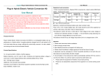
1. Removing the Rear display filter
•
•
1) Remove the two Screws 1.
2) Remove the Rear display filter 2.
Remove the two Screws 1.
Remove the Side cabinet 7.
Remove the Screw 2.
Remove the Printer cover 3.
Remove the Screw 4.
Remove the Top cabinet 8.
a) Release the latches a, b and c in that order. Slide the
upper cabinet to the right and release the latch on the right.
b) Lift the top cabinet and put it straight in the direction of arrow
A. ( Be careful not to pull the cable between the LCD I/F PWB
of the top cabinet and the MAIN PWB of the Bottom cabinet.)
c) Pull and remove the following cables between the LCD I/F
PWB of the top cabinet and the MAIN PWB of the Bottom
cabinet.
LCD Cable 5 : MAIN PWB : CN11
Earth wire 6.
7
1
2
A
1
8
1
4
2. Replacing the Rear display filter
Install the Rear display filter in the reverse order of removing.
5
2
3
6
9
4. Replacing the Top cabinet
Install the top cabinet in the reverse order of removing. Before installing, make sure that each connector is connected securely.
–1–
UP-5300VI
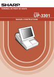
5. Removing the power supply unit
and AC cord
7. Removing the LCD unit
1) Remove the LCD unit 1.
a) Remove the three Screws 2.
Remove the two screws 1.
Remove the AC cord cover 2.
Remove the four screws 8.
Remove the P/S cover 7.
Use a minus screwdriver A to loosen the AC cord fixing screws (2
pcs.) of the power supply unit.
6) Remove the screw 4 and the earth wire 5 from the AC cord.
Remove the screw 8 of the holder securing the earth wire of the
AC cord.
7) Remove the power supply cable 6.
8) Remove the three screws 3.
1)
2)
3)
4)
5)
A
3
8
1
8
4
5
7
3
2
2
6
2) Remove the LCD rear cabinet 3.
a) Remove the two Screws 4.
b) Remove the pawls a to 1 of the LCD rear cabinet 3 in that
order.
3
g
8
f
e
d
h
c
b
i
j
a
k
4
2
3
1
6. Replacing the power supply unit
and AC cord
Install the in the power supply unit and AC cord in the reverse order
of removing.
Before installing, make sure that each connector is connected securely.
* When connecting the AC cord to the power supply unit in
assembly, tighten with the torque of 3 kg/cm ± 1 kg/cm.
Caution:
Please do not place the LCD unit on hard surfaces, Please take
special care not to place the LCD unit on any surface that may cause
damage to the unit.
–2–
UP-5300VI
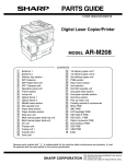
3) Remove the Inverter PWB 5.
a) Remove the Inverter cable 6.
b) Remove the CCFT cable 7.
c) Remove the two screws 8.
d) Remove the Inverter cover 9.
5) Remove the LCD M.
a) Remove the five Screws N.
b) Remove the LCD plate O.
c) Remove the LCD PWB unit P.
18
8
6
9
1 0
19
5
18
18
7
18
20
17
4) Remove the Touch panel PWB unit F.
a) Remove the LCD cable(40P) G.
b) Remove the LCD cable(30P) H.
c) Remove the Inverter cable I.
d) Remove the two Screws J and the two Earth wire K.
e) Remove the Screw L.
L o c k
U n lo c k
Touch panel
L o c k
8. Replacing the LCD unit
L o c k
U n lo c k
Install the LCD unit in the reverse order of removing.
Before installing, make sure that each cables are connected securely.
U n lo c k
9. PS-RAM DISK: UP-P02MB
1 4
1 5
1 1
Make sure to save data before installing this option.
1 6
1 5
1) Remove the Rear display filter.
2) Install the option RAM disk 1 to the Option ROM/RAM connector
CN15 2 on the Main PWB.
a) Insert the RAM disk aslant into the option ROM/RAM connector .
b) Push the RAM disk until the RAM disk is locked by the arms of
option ROM/RAM connector.
* It is possible to install one UP-P02MB.
* Be careful of the direction of RAM disk to be installed. Install
the RAM disk with the notch part of the PWB (Figure A) come
right. Installing the RAM disk in the wrong direction may
damage the connector part or make the machine out of order.
1 2
1 0
1 3
–3–
UP-5300VI
* Be careful of the direction of ROM disk to be installed. Install
the ROM disk with the notch part of the PWB (Figure A) come
right. Installing the ROM disk in the wrong direction may
damage the connector part or make the machine out of order.
A
A
2
2
1
1
in s ta llin g o n e R A M
d is k o n th e u p p e r
s lo t.
in s ta llin g o n e R A M
d is k o n th e lo w e r
s lo t.
in s ta llin g o n e R O M
d is k o n th e u p p e r
s lo t.
3) Removing the option RAM disk.
a) Open the arms of option ROM/RAM connector right and left.
b) The RAM disk will be lifted automatically.
in s ta llin g o n e R O M
d is k o n th e lo w e r
s lo t.
3) Remove the option ROM disk.
a) Open the arms of option ROM/RAM connector right and left.
b) The ROM disk will be lifted automatically.
10. F-ROM DISK: UP-F04RB
11. Cautions for UP-F04RB and
UP-P02MB
Make sure to save data before installing this option.
1) Remove the Rear display filter.
2) Install the option ROM disk 1 to the Option ROM/RAM connector
CN15 2 on the Main PWB.
a) Insert the ROM disk at a slant into the option ROM/RAM connector.
b) Push the ROM disk until the ROM disk is locked by the arms of
option ROM/RAM connector.
* It is possible to install one UP-F04RB.
Caution 1
Back up all data in the standard RAM disk (PS-RAM) before installing
the UP-F04RB/UP-P02MB.
Caution 2
Do not insert the UP-F04RB/UP-P02MB upside down into the connector on the UP-5300 main PWB.
If you try to insert the UP-F04RB/UP-P02MB upside down, the UPF04RB/UP-P02MB can only be inserted halfway.
The RAM disk on the UP-5300 may be broken.
–4–
UP-5300VI
Always insert the UP-F04RB/UP-P02MB with its upper side directed
upwards (The upper side of UP-F04RB/UP-P02MB is the same side
as the notch of the connector part).
45°
30° ~ 40°
U p p e r s id e
Upper slot
Lower slot
2) Grab the UP-F04RB/UP-P02MB’s PWB on the center part to push
down by sliding on the arms of the connector’s both sides using
the PWB’s terminal side as an axis until the arms click.
If the arms are too hard to push the UP-F04RB/UP-P02MB down
smoothly, push the UP-F04RB/UP-P02MB down from above with
opening the arms of the both sides of the connector right and left
using your fingers.
Click
Pawl
Caution 3
Install and remove the UP-F04RB/UP-P02MB as follows:
Handling the UP-F04RB/UP-P02MB forcibly may break the connector
lever.
Removing UP-F04RB/UP-P02MB
1) Open the arms of connector’s both sides using your fingers.
Installing UP-F04RB/UP-P02MB
Pawl
1) Insert the terminal side of UP-F04RB/UP-P02MB into the connector with the parts face upwards.
U p p e r s id e
Pawl
2) Check that the arms of the both sides are off and the UPF04RB/UP-P02MB stands at an angle of 30 to 40 degrees on the
upper slot against the main PWB or at an angle of 45 degrees on
the lower slot against the main PWB.
45°
30° ~ 40°
Upper slot
Lower slot
For the lower slot, the UP-F04RB/UP-P02MB may be caught in
the arms of the upper slot and stopped on the way to stand up.
Check that the UP-F04RB/UP-P02MB stands up to about an
angle of 45 degrees by further opening the both arms of the upper
slot right and left.
3) Pull the UP-F04RB/UP-P02MB out of the connector along the
inclination with which the UP-F04RB/UP-P02MB stood up.
Push the center part of UP-F04RB/UP-P02MB’s PWB onto the
upper slot at an angle of 30 to 40 degrees or onto the lower slot at
an angle of 45 degrees against the main PWB to insert until it hits
the back of the connector.
–5–
UP-5300VI
Caution 4)
Do not insert any general-purpose RAM board (additional DIMM
module) in the connector.
The connector has the signal assignment designed only for the UP5300.
If you erroneously insert a general-purpose RAM board into the connector, the UP-5300 and general-purpose RAM board may be
damaged.
12. D-RAM disk: S.O. DIMM (Locally supplied)
[Outline] UP-5300 has a socket as Small Outline DIMM.
It is necessary to satisfy with S.O.DIMM memory specification as follows.
[Specification]
144pin S.O.DIMM
8 Mbytes
16 Mbytes
TYPE
ACCESS TIME
60 nsec. (less than)
POWER
REFRESH CYCLE
3.3 V
1024/16 msec.
2048/32 msec.
REFRESH TYPE
4096/64 msec.
CBR
POWER CONSUMPTION
OTHER
32 Mbytes
EDO type
700 mA (less than)
4 chip × 16 Mbits
(1 Mwords × 16 bits)
8 chip × 16 Mbits
(2 Mwords × 8 bits)
4 chip × 64 Mbits
(4 Mwords × 16 bits)
Make sure to save data before installing this option.
1)
2)
3)
4)
5)
Remove the top cabinet.
Remove the three screws 1.
Remove the shield plate 4.
Remove the VGA PWB 5.
Install the option D-RAM disk 2 to the D-RAM connector: CN13
3 on the CPU PWB.
a) Insert a D-RAM disk at a slant into the D-RAM connector.
b) Push the D-RAM disk until the D-RAM disk is correctly locked
by the arms of D-RAM connector.
6) Connect the VGA PWB 5.
7) Fix the shield plate 4 with three screws 1.
1
4
5
2
3
–6–
UP-5300VI
8) Remove the option D-RAM disk.
a) Open the arms of D-RAM connector right and left.
b) The D-RAM disk will be lifted automatically.
15. RS232 & CENTRO I/F: ER-A8RS
E R -A 8 R S
c o n n e c tio n
13. MCR UNIT: UP-E12MR2
* Adjust the IRQ10 and IRQ11.
(See the "13. Adjusting the IRQ10/11 on the ISA PWB.")
1) Remove the REAR COVER.
2) Remove the screw 1 from the ISA BUS SHASSIS.
3) Insert the I/F PWB 2 to the ISA BUS CONNECTOR.
4) Fix the I/F BRACKET to the ISA BUS SHASSIS with screw 1.
* Only one ER-A8RS can be installed.
5) Connect the RS232 3 and CENTRONICS 4 cables to the I/F
PWB.
1) Fix the MCR ANGLE 1 to the lower cabinet with two screws 2.
2) Connect the MCR cable 3 to the MCR connector with the cable
holder 6, and tighter the screw 7 on the back of lower cabinet.
3) Install the ferrite Core 4 to the MCR cable and GND wire 5.
1
2
4
6
2
3
3
5
4
7
3
* If an I/F (locally supplied half-size PC card) other than the ERA8RS is connected to the ISA bus connector, it may be required to
remove reinforcement angle 5 when inserting the I/F.
In this case, remove reinforcement angle 5, insert the I/F, then
install reinforcement angle 5.
4) Fix the earth wire 5 from the UP-E12MR2 with the screw.
14. Adjusting the IRQ10/11 on the
ISA PWB.
Adjust the IRQ10 and IRQ11 using the switches: S1 and S2 on the
ISA PWB if an option equipment is connected to the ISA slot of the
ISA PWB.
IRQ11
M
(3)
S2
IRQ10
S
(1)
M
(3)
S1
1
S
(1)
5
S1 = IRQ10: S = ON (Connect IRQ10 to the ISA Slot.)
M = OFF (Connect IRQ10 to GND, not to the ISA Slot.)
S2 = IRQ11: S = ON (Connect IRQ11 to the ISA Slot.)
M = OFF (Connect IRQ11 to GND, not to the ISA Slot.)
–7–
UP-5300VI
3) Connect the display cable 4 to the connector: CN: 1 on the Main
PWB
4) Install the Display unit 5 to the cabinet
a) Align the positioning boss A of the bottom cabinet with the
angle hole A in the display unit.
* Align threaded holes completely before securing the I/F PWB with
screws.
16. REAR DISPLAY UP-I20DP
1) Remove the Display filter 1
17. POLE DISPLAY: UP-P20DP
1) Install the core 6 to the display cable 1.
2) Install the core 7 to the display earth cable 4.
3) Connect the Display cable 1 to the remote display connector on
the back of the set.
4) Fix the display cable 1 with the cable holder 2, and tighten the
screw 3 on the back of bottom cabinet.
5) Fix the display earth cable 4 to the main chassis with the screw
5.
2) Remove the Rear cover angle 2 from the Display filter 1
a) Remove the two Screws 3
5
4
7
1
6
3
2
* Cable holder 2
Use the following type of cable holder supplied with the UPP20DP.
• "3N" (large type)
–8–
UP-5300VI
5) Remove the two screws 6.
6) Remove the Base cabinet 4 from the pole cabinet 7.
* How to Extend Display Pole
The pole can be extended by installing the attached pole to the
standard pole.
7
COMPONENT LIST:
No.
7, G
NAME
USE
4
Q’ty
Pole cabinet
Pole extension
2
H
Screw (M3 × 4)
Pole connection
4
I
Screw (M4 × 16)
Securing the UP-P20DP to
the wooden table
4
J
Screw (M4 × 20)
Securing the UP-P20DP to
the metal table
4
K
Nut
Securing the UP-P20DP to
the metal table
4
L
Display cable (S)
M
Earth wire (S)
This display cable (S)
should be used instead of
the standard cable and
earth wire if the UP-20DP’s
standard pole is removed
to lower the height of the
UP-20DP.
1
1
6
1) Remove the five screws 1.
7) Pull the Ratchet 9 attached to the pole cabinet 7 out of the
Display unit 8 by turning it as shown in Figure A.
8) Remove the two screws F.
9) Remove the pole cabinet 7 from the Ratchet 9.
2) Remove the Base angle 2.
3) Remove the PWB unit 3 from the Base cabinet 4.
4) Remove the display cable 5 from the PWB unit 3.
Pattern side(PWB)
8
4
10
Core
9
2
7
10
1
9
3
1
5
–9–
UP-5300VI
10) Install the attached pole cabinet G to the pole cabinet 7 to fix it
with the screw H.
* Lowering the height of the UP-P20DP
Remove the standard Pole and attach the Base cabinet 4 to the
Ratch 9. At this time, replace the standard Display cable and the
Earth wire with the S type cable L and wire M.
7
Display cable
7
18. DRAWER UNIT:
ER-03DW/04DW/05DW
11
11
1) Connect the drawer cable 1 to the drawer connector 2.
2) Fix the earth wire 3 to the main chassis from drawer box unit with
the screw 4.
11) Install the pole cabinet G in the opposite order of the disassembly.
12) Fastening onthe table:
Secure the Base cabinet 2 using the screw.
No.
NAME
USE
Q’ty
I
Screw (M4 × 16)
Securing the UP-P20DP to
the wooden table
4
J
Screw (M4 × 20)
Securing the UP-P20DP to
the metal table
4
K
Nut
Securing the UP-P20DP to
the metal table
4
B
A
4
3
1 tu rn
7
6
2
1
5
3) Install the ferrite Core 5 to the drawer cable.
4) Fix the drawer cable 1 with the cable holder 6, and tighten the
screw 7 on the back of lower cabinet A or B.
– 10 –
UP-5300VI
Main PWB
19. COM1, COM2, COM3/5, and
COM4/6 Connector
1) COM1 & COM2
• D-SUB 9pin Connector
• CI signal of COM1 or COM2 and +5V power supply can be
switched in order to supply +5V power.
1
1
S 1
S 2
Connector Specifications
D-SUB9
3
3
Pin No.
Signal
1
CD
Data Carrier Detect
I
2
RD
Receive Data
I
3
SD
Send Data
O
4
ER
Data Terminal Ready
O
5
SG
Signal Ground
—
6
DR
Data set Ready
I
7
RS
Request to Send
O
8
CS
9
CI/+5V
Function
Clear to Send
Ring Indicate/+5V
I/O
S2 = COM1: 1 = +5V
3 = CI
S1 = COM2: 1 = +5V
3 = CI
I
I/–
+ 5 V
1
1
S 2
S 1
3
3
C O M 2
C O M 1
C I
1
1
S 2
S 1
3
3
– 11 –
UP-5300VI
2) COM3/5, COM4/6
• Two channels of COM port with an RJ45 connector are
equipped.
• For 2 channels of RJ45 COM port, COM3 & COM4 or an I/O
address (COM5 & COM6) can be selected.
• Two CABLE HOLDER 1 and SCREW (M3 × 8) 2 are contained in the package.
2
1
2
1
4
3
5
Fig. 1
Connector Specifications
RJ45
Pin No.
1
2
3
4
5
6
7
8
Signal
RS
ER
SD
SG
SG
RD
DR
CS
Function
Request to Send
Data terminal Ready
Send Data
Signal Ground
Signal Ground
Receive Data
Data set Ready
Clear to Send
2) Install the PS+CONTROL PWB 6.
a) Fix the PS+CONTROL PWB 6 with three SCREWs 7 Z, 3
* SCREW 3: Use the screw which was fixing the CLAMP 4
I/O
O
O
O
—
—
I
I
I
3) Connect the POWER SUPPLY CABLE 5 to the
PS+CONTROL PWB 6. (No. CN1)
4) Connect the I/F CABLE 8 of the PS+CONTROL
PWB 6 to the UP-5300 MAIN PWB (No.CN109)
20. BUILT-IN PRINTER: UP-T80BP
1) Remove the BOTTOM PLATE 2.
a) Remove the three SCREWs 1.
b) Remove the BOTTOM PLATE 2.
c) Remove the SCREW 3, CABLE CLAMP 4 and POWER SUPPLY CABLE 5.
8
30
5
3
7
30 : XEBSD30P08000
6
7 : XHBSD30P06000
Fig. 2
– 12 –
UP-5300VI
5) Remove the PRINTER LID 9.
8) Install the AUTO CUTTER RELAY PWB UNIT J.
a) Remove the screw F.
b) Remove the PRINTER LID 9.
a) Install the AUTO CUTTER RELAY PWB UNIT J with SCREW
K.
b) Pass the AUTO CUTTER RELAY PWB CABLE L through the
hole (C).
6) Install the PAPER ROLLERs (4ea.) G.
9
15
15 : XEBSD30P08000
11
16
C
14
Fig. 5
9) Install the PAPER GUIDE M to the PRINTER
UNIT N.
10
10) Install the HEAD CABLE O to the PRINTER
UNIT N.
Fig. 3
7) Install the SWITCH UNIT H.
a) Fix the SWITCH UNIT H on the cabinet pawl A.
b) Pass the SWITCH UNIT CABLE I through the hole (B).
17
19
12
12
A
13
B
A
Fig. 4
18
Fig. 6
– 13 –
UP-5300VI
11) Install the PRINTER UNIT N.
12) Wiring for each cables as shown below
a) Connect the AUTO CUTTER CABLE P to the AUTO CUTTER
RELAY PWB J.
b) Pass the HEAD CABLE O through the hole (C).
c) Pass the MOTOR CABLE Q and SENSOR CABLE R through
the hole (D).
d) Open the PRINTER UNIT N.
e) Fix the PRINTER UNIT N with four SCREWs S
* Fix the SCREWs S in the order of S-(a) to S-(d).
f) Fix the two EARTH WIREs T with a SCREW U.
23
a : XEBSD26P06000
23
b : XEBSD26P06000
23
c : XEBSD26P08000
23
d : XEBSD26P08000
23
23
c
23
a
20
25 : XHBSD30P06000
14
d
18
16
25
19
24
23
b
13) Connect the Printer cables to the CONTROL
PWB.
22
a) SWITCH UNIT CABLE I: Connect to the CN7.
b) HEAD CABLE O: Connect to the CN5.
Attach the FERRITE CORE (L size) V and
CABLE CLAMP 4.
Fix the CABLE CLAMP 4 with a SCREW X.
c) AUTO CUTTER RELAY PWB CABLE L: Connect to the CN4.
d) MOTOR CABLE Q: Connect to the CN2.
e) SENSOR CABLE R: Connect to the CN6
19
21
20
C
28 : XEBSD30P08000
D
14
16
28
Fig. 7
4
26
16
21
19
13
22
Fig. 8
– 14 –
UP-5300VI
14) Wiring for each cables as shown below
a) Attach the FERRITE CORE (S size) Y to the I/F CABLE 8.
b) Fix the I/F CABLE 8 and EARTH WIRE [ with the CABLE
BAND Z.
c) Set the switch: SW2 to the "MRS" position.
Fig. 9
15) Install the BOTTOM PLATE 2.
16) Install the PRINTER COVER Y.
29
2
1
Fig. 11
Fig. 10
– 15 –
UP-5300VI
1. LIST FOR SCREWs
L
M
No.
PARTS CODE
M [mm]
L [mm]
K
Z
X
S-a
S-b
S-c
S-d
XEBSD30P08000
3
8
XEBSD26P06000
2.6
6
XEBSD26P08000
2.6
8
21. HDD (UNIT: HZ-F21HD) & HDD
KIT: DKIT-8671RCZZ
* HDD KIT (DKIT-8671RCZZ) is an option for KB. (Standard for TQ,
TS)
[Outline] UP-5300 can connect to a specific Hard Disk Drive as local
purchase.
It is necessary to provide the following 2.5 inch Hard Disk
Drive specification as follows.
[Specification]
2.5 inch type Hard Disk Drive
7
U
XHBSD30P06000
3
8
MAKER
FUJITSU
MODEL
MHA2021AT
PARTS No.
REVISION No.
1) Part No.: CA01640-B040 (For local purchase)
Rev. No.: A4
CAPACITY
L
2.16 Gbytes
INTERFACE
ATA-3
* The hard disk drive is a part which is supplied locally.
M
COMPONENT LIST:
2. INSTALLATION OF PAPER NEAR END SENSOR
No.
NAME
[PARTS LIST]
1
2
3
4
5
6
7
HDD COVER A
1
HDD COVER B
1
ANGLE
2
HDD CUSHION
4
SPACER
4
SCREW A (M3 × 4)
4
SCREW C (M3 × 8)
4
8
9
F
G
H
SCREW B (M3 × 14)
4
WASHIER
4
HDD CABLE
1
FERRITE CORE
2
HOLDER
2
No.
PARTS NAME
1
PAPER NEAR
END SENSOR
NEAR END
SENSOR
CONNECTOR
2
PARTS CODE
NOTE
DUNTK3819BHZZ
SENSOR UNIT,
FIXING SCREW
QCNCM6865RC0B
2 pin connector
1. Remove the BOTTOM PLATE .
2. Remove the PS+CONTROL PWB .
3. Solder the CONNECTOR 1 to the PS+CONTROL PWB (No.
CN1)
4. Install the NEAR END SENSOR UNIT 2 to the CABINET , and fix
it with the fixing SCREW 3.
Q’ty
1) Install the HDD COVER A 1 to the HDD unit with the SCREW A
(M3 × 4) 6.
* Install the HDD unit in the correct direction so that the HDD unit
firmly fits onthe HDD COVER A 1.
2
3
1
Fig. 12
– 16 –
UP-5300VI
2) Install the HDD CUSHION 4 to the ANGLE 3.
3) Insert the SPACER 5 to the HDD CUSHION 4.
4) Install the HDD COVER B 2 and the ANGLE 3 to the HDD
COVER A 1 with the WASHIER 9 and SCREW B (M3 × 14)
8.
5) Place the ferrite core G in the center of the HDD cable F and
secure with the holder H.
6) Connect the HDD CABLE F to the HDD unit.
* Connect the HDD CABLE F with the 4 pins on the left side of
the HDD unit open as shown in Figure A.
7) Remove the Bottom plate I.
8) Connect the HDD CABLE F to the HDD connector: CN108 on
the MAIN PWB.
9) Install the HDD unit to the Bottom cabinet. With the SCREW A
(M3 × 8) 7.
8
9
4
5
3
6
8
4
9
5
4
4
1
3
11
10
22. FDD UNIT: UP-H14FD
12
COMPONENT LIST:
2
A
1 pin
No.
NAME
1
FDD UNIT
1
2
3
4
5
6
7
8
9
F
FDD ANGLE-A
2
FDD ANGLE-B
1
SCREW
4
SCREW
4
EARTH WIRE
1
FDD CABLE
1
FDD COVER-A
1
FDD COVER-B
1
FERRITE CORE
1
1) Remove to the Printer lid 1.
a) Remove the screw 2.
b) Remove the printer lid 1.
2) Remove the bottom plate 4.
a) Remove the three screws 5.
b) Remove the bottom plate 4.
3) Remove the FDD cover 7.
– 17 –
Q’ty
UP-5300VI
7) Install the FDD UNIT G to the UP-5300.
a) Install the FDD UNIT G and FDD ANGLE-B J to the bottom
cabinet with the four screws K.
b) Connect the FDD CABLE I to the Main PWB.
c) Pass the EARTH WIRE F through the hole A.
d) Install the EARTH WIRE F with the screw L.
1
2
11
14
7
4
17
15
10
15
5
A
4) Install the FDD ANGLE-A 8.
a) Install the two FDD ANGLE-A 8 and EARTH WIRE F to the
FDD UNIT G with the four screws H.
5) Connect the FDD CABLE I to the FDD UNIT G.
6) Install the ferrite core M onto the FDD cable I.
16
10
1 2
1 1
1 0
8
1 7
1 3
8
1 2
– 18 –
13
UP-5300VI
8) Install the FDD COVER M to the FDD FRONT COVER N.
* Keyboard 1 is tightly engaged and hard to be removed.
When removing it, use nippers to cut off four pawls A from the
back of the upper cabinet.
1 8
B a c k o f th e u p p e r c a b in e t
P a w ls A
P a w ls A
P a w ls B
1 7
P a w ls B
9) Install the FDD COVER UNIT M, N to the bottom cabinet.
3) Attach the keyboard cover 2 and keyboard unit 3 to theupper
cabinet, and fix them with four screws 4.
1 7
1 8
23. KEY PAD: UP-C30PK
1) Remove the upper cabinet.
2) Remove the keyboard lid 1 from the upper cabinet.
– 19 –
UP-5300VI
* When attaching keyboard cover 2, engage pawls C and D securely with the upper cabinet.
B a c k o f th e u p p e r c a b in e t
P a w ls D
P a w ls C
4) Connect the cable of the keyboard unit 3 to the main PWB connector CN10.
5) Attach the earth spring 5 to the lower cabinet with thescrew 6.
– 20 –
UP-5300VI
q
COPYRIGHT 1999 BY SHARP CORPORATION
All rights reserved.
Printed in Japan.
No part of this publication may be reproduced,
stored in a retrieval system, or transmitted.
In any form or by any means,
electronic, mechanical, photocopying, recording, or otherwise,
without prior written permission of the publisher.
SHARP CORPORATION
Information Systems Group
Quality & Reliability Control Center
Yamatokoriyama, Nara 639-1186, Japan
1999 July Printed in Japan T