1
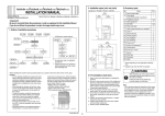
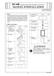
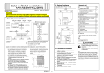
Color MFP 45/45 ppm (45C-5)
INSTALLATION MANUAL
II. Installation space (unit: mm (inch))
IV. Accessory parts
Color MFP 45/45 ppm (45C-5) + FS-527 + LU-204
No.
1. Imaging unit (IU): Y,M,C
2148 (84-9/16)
Applied Machine: Color MFP 45/45 ppm (45C-5)
658
(25-7/8)
1252
(49-5/16)
Name
238
(9-3/8)
Q’ty
3
2. Developing unit: K
1
3. Drum unit: K
1
<Important>
Be sure to correctly follow the procedures in order as explained in this Installation Manual.
If you do not follow the procedure in order, the image trouble may occur.
4. User’s guide holder
1
5. Installation manual
1 set
6. CD-ROM *
1 set
7. Tray label
1
I. Outline of installation procedures
8. Paper size label
1
9. Label (Legal restrictions on copying) *
AU-101
AU-102
WT-506
AU-201
KH-101
LU-204
✱ Electron system options
Machine
LU-301
EK-604*2
1575 (62-1/16)
EK-605*2
418
(16-7/16)
HT-508*1
*2
IC-412
JS-504
OT-503
MK-720*2
FK-502
SD-509
495
(19-1/2)
JS-603
SC-507*2
*1
*2
: Varies depending on the applicable marketing area.
: No particular order in installation procedures.
11. Chart
1
12. Cap A (black)
2
13. Cap B (white)
2
14. Connector cover
1
15. IR Cover
1
16. Mounting screw
1
17. Spacer A
1
18. Spacer B
1
19. Power cord instruction *
1
20. Panel pen
1
A0P2IXC002DA
III. Pre-installation check items
When installing the machine and associated options as a system, follow the order shown on the upper.
Note:
• For the detailed installation procedures for each option, follow the instructions given in the corresponding
installation manual and perform the procedures correctly.
• Once the Power Switch is turned ON, do not turn OFF it until the installation work has been completed.
• When transporting the machine, assign an adequate number of persons to the job and follow the specified correct procedures.
(mass: approx. 221 kg (487-1/4 lb))
1. Select a level and stable place for installing the
machine.
2. Be sure to use a power source of the voltage and
frequency indicated in the product specifications.
Ensure that the current carrying capacity of the
power outlet is at least equal to the current listed
in the product specifications.
3. Power the machine directly from a dedicated
power outlet. (Do not use an extension cord.)
4. Do not plug or unplug the power cord with wet or
dirty hands, otherwise you may get an electric
shock.
5. Avoid a hot and humid environment, or a place
exposed to direct sunlight.
6. Avoid a dusty location, or a place near volatile
and flammable substances.
7. Avoid a poorly ventilated place.
A0P2IXC001DA
A0P2-9960-00
1
* Varies depending on the applicable marketing
area.
Note:
Keep the label (Super G3 label) at hand. It is necessary for mounting the FAX Kit.
1155
(45-1/2)
VI-505*2
1650 (64-15/16)
Electron system options
FS-527
50
(2)
UK-203*2
SP-501
PK-517
1107
(43-9/16)
1
10. Label (Super G3 label)
E-1
After unpacking, be sure to get rid of the
packaging materials and keep them out of
the reach of children.
Putting the head in the plastic bag
involves danger of suffocation.
V. Unpacking the machine
1. Open the shipping box and take out the IU shipping box and packaging material.
Note:
• Save the slope and cushion removed here for
later use.
• When storing or moving the IU, be sure to face
the TOP side up.
6. Position the slope as illustrated and drive nails in
to fix the slope in position.
Note:
Insert the nails in the outer holes.
3. Hold onto the handle of the machine and tilt the
machine to the right and left. Under this condition,
remove the mirror mat and fixing material (lower).
VI. Removing protective tape, packing and
other shipping materials
1. Remove the protective tape and protective material.
Note:
After removing protective tape B, be sure to lock
the lever.
Cushion
B
A
A0P0IXC017DB
A0P0IXC020DA
Slope
7. Holding onto the front cover and the back panel
of the machine, slide the machine down along the
slope.
Note:
Machine mass: 207 kg (456-1/4 lb)
• Perform this step on a level, stable site and
assign an adequate number of persons.
• When sliding the machine down, do not hold
onto the IR portion.
• Do not insert your leg under the slope.
IU
A0P0IXC014DA
2. Remove the fixing material (upper).
<Viewed from point A>
A0P0IXE069DD
A0P0IXC018DB
4. Separate the cushion into two and install them to
the pallet (at two places).
A0P0IXC068DA
A0P0IXC015DA
A0P0IXC021DA
A0P0IXC019DA
5. Take out the slope and protective tape and
remove nails from the plastic bag.
A0P0IXE070DB
A0P0IXC016DB
A0P0IXC044DB
A0P0IXC067DA
E-2
2. Remove the protective material.
8. Remove the protective tape from trays 3 and 4.
5. Pull the tray 1 out and remove the protective tape
from the tray.
A0P0IXC045DA
3. Tilt the IU to the right and, in that condition, shake
it over a small stroke twice. Then, tilt the IU to the
left and, in that condition, shake it over a small
stroke twice.
Note:
• Perform this step only for the color IU (Y, M,
and C).
• Shake the IU adequately. Otherwise, it may
cause trouble.
A0P0IXC023DB
A0P0IXC048DA
3. Remove the reinforcement plate (four screws).
6. Pull the tray 2 out and remove the protective tape
from the tray.
VII. Installing the IU
1. Open the lower front door.
A00JIXC028DB
4. Remove protective tape of the IU.
A0P0IXC046DA
4. Remove the packing bracket.
Note:
Do not loosen or remove the shoulder screw from
the portion on which the packing bracket A is
mounted.
A0P0IXC049DA
A0P0IXC007DA
7. Pull trays 3 and 4 out and remove the desiccant
and protective sheet.
2. Remove the waste toner box fixing lever and the
waste toner box.
A00JIXC228DA
5. Remove the protective sheet.
Protective sheet
Packing
bracket A
A0P0IXC022DB
A0P0IXC008DA
A0P0IXC047DA
A00JIXC030DC
E-3
9. Fix the IU in position using the IU fixing lever.
6. Unlock the IU fixing lever.
A0P0IXC024DA
13. Hold the developing unit upside down and
remove the cap.
16. Remove the protective material.
A0P0IXC027DA
A0P0IXC034DB
A0P0IXC081DA
7. Keeping the IU in the level position, insert it all
the way as far as it will go.
Note:
Make sure that the color is same between inserting port and the IU.
10. Using the same procedure, install all IUs.
11. Remove the tape and the mounting bracket from
the position shown below of the developing unit.
17. Slide out the rail from the machine.
14. Remove the protective tape.
Note:
Be careful that developer does not spill from the
hole on the developing unit.
A0P0IXC035DA
18. Remove one shoulder screw.
A0P0IXC028DB
12. Remove two springs and a shutter, which are
used in step 15, from the bag.
A0P0IXC082DA
15. Attach the two springs and the shutter removed
in step 12 to the developing unit.
A0P0IXC025DA
8. Push the IU all the way in.
Note:
Make sure that the IU is pushed all the way in.
A0P0IXC036DB
A0P0IXC079DA
A0P0IXC083DA
A0P0IXC026DA
E-4
19. While aligning part A of the developing unit with
the screw hole on the rail, pass part B of the
developing unit under the rail.
21. Fix the developing unit to the rail using the
shoulder screw removed in step 18.
23. Put the drum unit on the developing unit.
Note:
• Do not tilt the drum unit when putting it on the
developing unit. (Keep the drum unit level.)
• Position the drum unit so that part A of the drum
unit is inserted into part B of the developing
unit.
• Position the drum unit so that part C of the
drum unit is inside the mylar located on the
main body rail. (Check that Part C is not on the
top of the rail.)
Part A
24. Peel off the protective sheet of the drum unit.
A0P0IXC041DB
A0P0IXC038DB
25. Secure the drum unit to the developing unit with
the two levers.
Note:
• Push the front and back levers in the direction
of the arrow at a time to secure the drum unit.
• Check that the front lever of the drum unit is
parallel to the vertical line marked on the label
on the developing unit.
22. Remove the caps from the front and rear ends of
the drum unit.
Part A
Part B
A0P0IXC080DA
20. Align part A of the developing unit with part B of
the rail and place the developing unit on the rail
of the machine.
Note:
Make sure that the positioning metal bracket of the
rail fits in the cutout in the developing unit.
Part B
A0P0IXC071DA
Mylar
A0P0IXC039DA
Part A
Part B
OK
Cutout
NG
Front lever
Parallel
Part C
A0P0IXC085DA
Label (Vertical line)
A0P0IXC040DC
Positioning
metal bracket
A0P0IXC037DB
E-5
VIII. Installing the toner cartridge
26. Insert the drum unit into the machine.
4. Insert the toner cartridge into the machine.
Note:
Make sure that the color is same between inserting port and the toner cartridge.
Note:
Since cartridge is not furnished with the machine,
purchase toner cartridge (of different colors) separately.
1. Open the upper front door.
IX. Connecting the power cord and
mounting the accessory parts
1. Connect the power cord.
Note:
This step may not be performed depending on the
applicable marketing area.
A0P0IXC042DA
27. Tighten one shoulder screw to secure the drum
unit to the machine.
A00JIXC019DA
5. Push the toner cartridge all the way in.
Note:
Make sure that the toner cartridge is pushed all the
way in.
A00JIXC017DA
2. Shake the toner cartridge up and down five to ten
times.
Note:
Shake the cartridge adequately. Otherwise, it may
cause trouble.
A0P0IXE075DA
2. Plug the power cord into the power outlet.
A0P0IXC043DA
28. Remove the protective tape and protective
material from the waste toner box that has been
removed in step 2.
C4004u139CA
A00JIXC139DA
6. Using the same procedure, install the toner cartridges for other colors of toner.
7. Close the upper front door.
A00JIXC018DA
3. Remove protective tape of the toner cartridge.
3. To remove moisture from the paper in the tray,
turn ON the switch shown in the illustration.
Note:
This step may not be performed depending on the
applicable marketing area.
A0P0IXC009DA
29. Reinstall the waste toner box.
30. Close the lower front door.
Switch
A00JIXC224DA
A0P0IXE076DA
E-6
4. Attach the cap A and B furnished with the
machine.
7. Install the spacer A furnished with the machine.
X. Installing the user’s guide holder
XI. Adjusting touch panel
Install the user’s guide holder.
1. Turn ON the Main Power Switch and then Sub
Power Switch.
2. Press the accessibility key.
3. Touch “Touch Panel Adjustment.”
4. Using the panel pen, lightly touch the center of
the + markers at four places on the touch panel.
(Any specific marker can be the first one.)
Note:
Pressing the touch panel hard may cause damage.
A0P0IXC053DA
A0P0IXC050DA
8. Install the spacer B furnished with the machine.
A00JIXC138DA
5. Install the IR cover furnished with the machine
(one mounting screw furnished with the
machine).
* When all the markers at four places have been
touched, the start key turns blue and lights up
steadily blue.
5. Press the start key.
6. Touch “Close.”
XII. Setting gradation adjust
1. Set that A3
or Ledger
paper is loaded in
the tray.
Note:
If the A3
or Ledger
paper is not readily
available, use A4
or Letter
paper.
2. Display the Service Mode screen.
(For details of how to display the Service Mode
screen, see the service manual.)
3. Touch “Imaging Process Adjustment.”
4. Touch “Gradation Adjust.”
5. Touch “Stabilizer” and press the start key.
* When the start key lights up blue, go to step 6.
Note:
When a maintenance call occurs, see the service
manual.
A0P0IXC054DA
A0P0IXC051DA
9. Set the panel pen in the pen holder at the control
panel.
6. Attach the connector cover furnished with the
machine.
A0P0IXC055DA
A0P0IXC052DA
E-7
<If A3
or Ledger
paper is set in step 1>
”, and
6. Touch “Print”, select “A3
/11×17
press the start key.
A test pattern will then be produced on the A3
or Ledger
paper.
7. Place the test pattern face down on the original
glass.
”, and
12. Touch “Copy”, select “A3
/11×17
press the start key.
A test pattern will then be produced on the
A3
or Ledger
paper.
13. Place the test pattern face down on the original
glass.
<If A4
or Letter
paper is set in step 1>
6. Touch “Print”, select “A4 /8½×11 ”, and
press the start key.
A test pattern will then be produced on the two
A4
or Letter
papers.
7. Place the test pattern face down on the original
glass.
Cyan
12. Touch “Copy”, select “A4 /8½×11 ”, and
press the start key.
A test pattern will then be produced on the two
A4
or Letter
papers.
13. Place the test pattern face down on the original
glass.
Cyan
Magenta
Magenta
A0P0IXC061DB
A0P0IXC062DB
A0P0IXC058DB
8. Place about ten sheets of A3
or Ledger
paper on the test pattern placed on the original
glass.
Lower the cover.
14. Place about ten sheets of A3
or Ledger
paper on the test pattern placed on the original
glass.
Lower the cover.
A0P0IXC060DB
8. Place about ten sheets of A3
or Ledger
paper on the test pattern placed on the original
glass.
Lower the cover.
14. Place about ten sheets of A3
or Ledger
paper on the test pattern placed on the original
glass.
Lower the cover.
A0P0IXC059DA
A0P0IXC059DA
A0P0IXC059DA
9. Press the start key.
The machine will start reading the test pattern.
10. When the machine completes reading the test
pattern, the “Gradation Adjust” screen will reappear.
11. Repeat steps from 6 through 9 to let the
machine read the test pattern two times.
15. Press the start key.
The machine will start reading the test pattern.
16. When the machine completes reading the test
pattern, the “Gradation Adjust” screen will reappear.
17. Repeat steps from 12 through 15 to let the
machine read the test pattern two times.
18. Touch “END.”
A0P0IXC059DA
9. Press the start key.
The machine will start reading the test pattern.
10. When the machine completes reading the test
pattern, the “Gradation Adjust” screen will reappear.
11. Repeat steps from 6 through 9 to let the
machine read the test pattern two times.
E-8
15. Press the start key.
The machine will start reading the test pattern.
16. When the machine completes reading the test
pattern, the “Gradation Adjust” screen will reappear.
17. Repeat steps from 12 through 15 to let the
machine read the test pattern two times.
18. Touch “END.”
XIII. Adjusting skew feed
Note:
Perform this adjustment if necessary.
1. Close the reverse automatic document feeder.
2. Plug the power cord into the power outlet and
turn on the machine.
3. Check how the edges of the chart are misaligned.
The amount of the deviation of the chart will be X.
X
Deviation in + (plus)
X
10. When the difference of the deviation is - (minus),
turn the screw clockwise to adjust.
Note:
When turning the screw, be sure not to raise the
reverse automatic document feeder until in an
upright position.
* To prevent the adjustment screw breakage, be
sure to follow the above instructions.
7. Obtain the difference between the deviation of
the chart and the deviation of the sample.
Difference of the deviation = Y - X
Specifications: 0 ± 2 mm
* If the difference of the deviation does not fall
within the specified range, perform the following
adjustment.
8. Loosen the mounting screw on the right hinge
viewed from the front.
9. When the difference of the deviation is + (plus),
turn the screw counterclockwise to adjust.
Note:
• When turning the screw, be sure not to raise the
reverse automatic document feeder until in an
upright position.
• When the adjusting plate is set far left, do not
tighten any further.
* To prevent the adjustment screw breakage, be
sure to follow the above instructions.
XIV. Adjusting the document stop position
Note:
Perform this adjustment if necessary.
1. Display the Service Mode screen.
(For details of how to display the Service Mode
screen, see the service manual.)
2. Touch “ADF.”
3. Touch “Feed Zoom.”
4. Touch “Auto Adjust.”
5. Place the chart in the document feeding tray (with
the side having an arrow facing up).
Mounting
screw
Deviation in - (minus)
A0P0IXC057DA
9J07IXC043DA
11. After the adjustment is completed, tighten the
mounting screws on right side hinge securely
with screwdriver.
4. Place the chart in the document feeding tray (with
the side having an arrow facing up).
Mounting
screw
6. Press the Start key.
7. Check that “Adjustment Result” is “OK” and then
touch “SET.”
8. Touch “END.”
9. Touch “Mixed original size adjustment.”
10. Place the chart in the document feeding tray
(lengthwise).
A0P0IXC056DA
A01HIXC011DC
5. Make copies 5 times repeatedly in single side
mode.
6. Fold all 5 sample copies as illustrated and check
for any deviation.
Deviation on the sample will be Y.
A01HIXC011DC
Adjusting plate
A01HIXC013DA
A0P0IXC075DA
Y
Deviation in + (plus)
Y
Deviation in - (minus)
9J07IXC043DA
E-9
11. Press the Start key.
12. Check that “Adjustment Result” is “OK” and then
touch “SET.”
13. Touch “END.”
14. Touch “Auto Stop Position Adjustment.”
15. Touch “Sub Scanning Direction 1-Side.”
16. Place the chart in the document feeding tray
(with the side having an arrow facing up).
21. Press the Start key.
22. Check that “Adjustment Result” is “OK” and then
touch “SET.”
23. Touch “Main Scanning (Front).”
24. Place the chart in the document feeding tray
(with the side having an arrow facing up).
XV. Non-image area erase check
XVI. Date/Time setting
1. Make sure that the Service Mode screen is displayed.
2. Select the Non-Image Area Erase Check function
as follows:
Machine →
→ Non-Image Area Erase Check.
Note:
• Open fully the reverse automatic document
feeder.
• Do NOT place a document on the document
glass.
• Clean the document glass if dirty.
1. Display the Service Mode screen.
(For details of how to display the Service Mode
screen, see the service manual.)
2. Display the Date & Time Setting screen.
(To display the Date & Time Setting screen, press
Stop → 1 → 1 → 4 → 4 → Clear on the control
panel.)
3. Press the clear key.
4. Enter the data for the year, month, day, and timeof-day from the 10-key pad.
5. Touch “Entry.”
Note:
Touching the Entry key returns the figures in the
Date & Time Setting screen to 0 and Date & Time
Setting has been completed.
6. Touch “END.”
7. Touch “Exit” on the Service Mode screen.
8. Select the Date/Time Setting function as follows:
Utility/Counter → Administrator Settings → Enter
the Administrator Password (Default setting:
12345678) → System Settings → Date/Time Settings.
9. Select the item you want to set and press the
clear key.
10. Enter the data for the year, month, day, and
time-of-day from the 10-key pad.
11. Touch “OK.”
12. Touch “Close” three times.
A01HIXC011DC
A01HIXC011DC
17. Press the Start key.
18. Check that “Adjustment Result” is “OK” and then
touch “SET.”
19. Touch “Sub Scanning Direction 2-Side.”
20. Place the chart in the document feeding tray
(Make sure that the blank surface of the chart
faces up).
25. Press the Start key.
26. Check that “Adjustment Result” is “OK” and then
touch “SET.”
27. Touch “Main Scanning (Back).”
28. Place the chart in the document feeding tray
(Make sure that the blank surface of the chart
faces up).
A0P0IXC091DA
3. Press the Start key.
4. Make sure that “Result” is “OK.”
Note:
If “Result” is “NG1” or “NG2”, review the place and
direction of installation, or take measures to block
the light source (by covering it, etc.), then perform
installation checking again.
(If a fluorescent light or other bright light sources
exist right above the machine, the light source can
hinder installation checking and cause operation
errors in the Non-Image Area Erase Check. For
detailed information, see the service manual.)
5. Touch “OK.”
6. Touch “Exit” on the Service Mode screen.
7. Turn OFF and ON the Main Power Switch.
Note:
When displayed the Service Mode screen, be sure
to turn off the main power after exiting the Service
Mode screen and wait for 10 seconds or more
before turning on.
A01HIXC015DC
A01HIXC015DC
29. Press the Start key.
30. Check that “Adjustment Result” is “OK” and then
touch “SET.”
31. Touch “END.”
32. Touch “Exit” on the Service Mode screen.
33. Turn OFF and ON the Main Power Switch.
Note:
When displayed the Service Mode screen, be sure
to turn off the main power after exiting the Service
Mode screen and wait for 10 seconds or more
before turning on.
E-10
XVII. Install date
1. Display the Service Mode screen.
(For details of how to display the Service Mode
screen, see the service manual.)
2. Select the Install Date function as follows:
System 1 → Install Date.
3. Press the clear key.
4. Enter the data for the year, month, and day from
the 10-key pad.
5. Touch “Entry.”
Note:
Touching the Entry key returns the figures in the
Install Date screen to 0 and Install Date has been
completed.
6. Touch “END.”
XVIII. Serial number input
XXI. Changing paper size (Tray 3 and 4)
Note:
Serial number input is needed only for optional
devices that will be installed later.
1. Select the Serial Number Input function as follows: System 1 → Serial Number.
2. Touch the item you want to enter and input the
serial number.
3. Touch “END.”
4. For other devices, enter their serial number in the
same way.
5. Touch “END.”
1. Turn OFF the Main Power Switch.
2. Pull out the tray 3.
3. Remove the front and rear paper guide plates
(four screws each).
Paper guide plate (rear)
5. Align the paper guide plate (rear) with the line
marked in the bottom of the tray. Secure the
paper guide plate (four screws).
Note:
Depending on paper size, the positioning method
of the paper guide plate (rear) is different.
< B5/8.5”/16K >
Insert the paper guide plate (rear) into the hole
and press it towards the rear end of the hole until it
stops. Secure the plate with screws.
Paper guide plate (front)
Insert the paper guide plate (rear) into the hole
and press it towards the front end of the hole until
it stops. Secure the plate with screws.
Note:
This function allows the user to select the type of
message that will appear when the replacement
time arrives for each of the different units.
1. Select the Unit Change function as follows:
System 2 → Unit Change.
2. Select the appropriate message type for each
unit.
3. Touch “END.”
1. Load the tray 1 with A4
or Letter
paper.
2. Touch “List Output.”
3. Check that “Machine Management List” is
selected and press the start key.
The list will be output.
4. Output “Adjustments List” in the same way.
5. Touch “2.”
6. Check that “Service Parameter” is selected and
press the start key.
The list will be output.
7. Touch “END.”
8. Touch “Exit” on the Service Mode screen.
9. Turn OFF and ON the Main Power Switch.
Note:
When displayed the Service Mode screen, be sure
to turn off the main power after exiting the Service
Mode screen and wait for 10 seconds or more
before turning on.
Affix the tray label or paper size label at the location
shown in the illustration.
Note:
If both are to be affixed, the tray label should be on
the upper side and the paper size label on the
lower side.
* For loading the paper as well as setting the paper
type, refer to the user’s guide.
< A5/POST >
XIX. Unit change
XX. List output
XXII. Affixing the tray labels
A0P0IXC065DA
XXIII. Affixing the label (Legal restrictions
on copying)
A0P0IXC063DA
Front
4. Remove the end guide plate (two screws).
Rear
A00JIXC227DB
6. Place a sheet of paper as large as the paper size
you are setting in the bottom of the tray. Align the
paper guide plate (front) with the end of the
sheet.
Gap between the sheet and the paper guide plate
(front): 1mm or less
7. Tighten the two front screws. Remove the sheet
and tighten the two rear screws.
8. Align the end guide plate with the line marked in
the bottom of the tray and secure it (two screws).
9. Close the tray 3.
10. Turn ON the Main Power Switch.
11. Display the Service Mode screen.
(For details of how to display the Service Mode
screen, see the service manual.)
12. Select the LCC size setting function as follows:
System 2 → LCC size setting.
13. Touch “Tray 3” and select the paper size that
was set for the tray 3.
14. Touch “END.”
15. Touch “Exit” on the Service Mode screen.
16. Turn OFF and ON the Main Power Switch.
Note:
When displayed the Service Mode screen, be sure
to turn off the main power after exiting the Service
Mode screen and wait for 10 seconds or more
before turning on.
17. Perform the same procedure for the tray 4.
A0P0IXC064DA
E-11
Affix the label (Legal restrictions on copying) to the
position shown below.
Note:
This step may not be performed depending on the
applicable marketing area.
Label
A0P0IXE078DA
XXIV. Check through test print
XXVI. Network setting
Make operation checks using “Setting Information
Print.”
1. Select the function to be used as follows:
Utility/Counter → User Settings → Printer Settings → Print Reports.
The types of the test prints that can be printed will
be displayed.
2. Touch “Configuration Page.”
3. Touch A4 size and press the start key.
Check that the machine produces the corresponding printed page.
4. Touch “Cancel” and then touch “Close” four
times.
Make the TCP/IP address setting for the network.
Note:
Consult the network administrator for the setting
value to be entered and make settings as
required.
1. Select the function to be used as follows:
Utility/Counter → Administrator Settings → Enter
the Administrator Password → Network Settings
→ TCP/IP Settings → IPv4 Settings.
2. Touch “Manual Input” of IP Address Setting
Method and make the following settings.
IP Address: IP address of the controller
Subnet Mask: Subnet mask of the network, to
which the machine is connected
Default Gateway: IP address of the default gateway
3. Touch “OK.”
4. Turn OFF and ON the Main Power Switch.
5. Select the function to be used as follows:
Utility/Counter → Administrator Setting → Enter
the Administrator Password → Network Settings
→ Forward → Detail Settings → PING Confirmation, and make the operation check of TCP/IP.
XXV. Connecting cables
1. Connect the networking equipment (HUB) using
the network cable.
Note:
The following shows the recommended network
cables that correspond to each communication
speed.
• 10BaseT/100BaseTX: Category 5
• 1000BaseT: Category 5E, Category 6
Networkport
LED1
LED2
A0P0IXC066DA
2. Check LEDs for lighting conditions.
LED1:
Should light up steadily if the link network connection has been made.
LED2:
Should blink according to the communications
status of the ACT network.
E-12