1
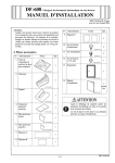
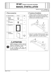
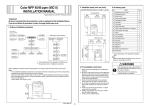
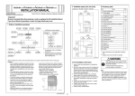
DF-617 Reverse Automatic Document Feeder
INSTALLATION MANUAL
Applied Machines: d-Color MF360/MF280/MF220
COLOR MFP: 36 ppm/28 ppm/22 ppm
Product Code: A0ED
Note:
Lifting the machine in an awkward position or
transporting it in a poorly balanced position could
result in personal injury. When transporting the
machine, assign an adequate number of persons
to the job and ensure that each person can take a
good position of not being excessively loaded.
(mass: approx. 16.7 kg (36-3/4 lb))
No.
Name
Shape
Q’ty
9. Chart
1
9J07IXC048DA
10. Installation
manual
I. Accessory parts
No.
Name
Shape
1 set
Q’ty
1. Reverse automatic document feeder
4980IXC019DA
1
A0HUIXC001DA
2. Protective
film (right)
After unpacking, be sure to get rid of the
packaging materials and keep them out of
the reach of children.
1
Putting the head in the plastic bag
involves danger of suffocation.
A01HIXC024DB
3. Protective
film (left)
Note:
This manual provides the illustrations of the accessory parts and machine that may be slightly different in shape from yours. In that case, instead of
the illustrations, use the appearance of your
machine to follow the installation procedure. This
does not cause any significant change or problem
with the procedure.
1
A01HIXC025DB
4. Film
1
A0HUIXC002DA
5. Label A
1
6. Label B
1
7. Shoulder
screw
2
4582U010AA
8. Mounting
screw
2
4582U011AA
Y111070-8
E-1
Installation Manual
II. Installation procedures
5. Place the reverse automatic document feeder in
position.
1. Turn off the machine and unplug the power cord
from the power outlet.
2. Hold the reverse automatic document feeder as
shown in the illustration and remove it from the
carton.
A01HIXC003DB
6. Using two mounting screws furnished with the
reverse automatic document feeder, tighten the
hinges to secure the reverse automatic document
feeder in position.
Note:
Tighten the mounting screws in order of ➀, ➁.
A0HUIXC003DA
3. Remove the protective tape and shipping preservatives and remove the protective vinyl bag of the
hookup cord.
➀
➁
A01HIXC004DB
7. Connect the hookup code to the machine.
A0HUIXC011DA
4. Screw two shoulder screws furnished with the
reverse automatic document feeder into the holes
in the rear (two shoulder screws).
A0HUIXC005DA
A01HIXC044DA
Installation Manual
E-2
Y111070-8
III. Adjusting the height
8. Affix the label A to the position shown below.
1. Check the clearance between the upper face of
scanner and the protrusion on the reverse automatic document feeder side (2 spots, front/back).
* There must be no clearance between the protrusion on the reverse automatic document feeder
and the upper face of scanner.
Label A
A0HUIXC006DA
9. Remove the indicated label from the reverse
automatic document feeder.
OK
NG
A01HIXC007DB
Protrusion
Protrusion
Label
A01HIXC047DA
A01HIXC008DA
Y111070-8
E-3
Installation Manual
IV. Adjusting skew feed
2. If there is any clearance, adjust the height by
turning the adjustment screw on the right side
viewed from the back.
Clockwise: The rear side will move up.
Counterclockwise: The rear side will move down.
• If further adjustment is required, adjust the height
by using the adjustment screw on the left side
viewed from the back together.
Clockwise: The rear side will move up.
Counterclockwise: The rear side will move down.
1. Close the reverse automatic document feeder.
2. Plug the power cord into the power outlet and
turn on the machine.
3. Check how the edges of the chart are misaligned.
The amount of the deviation of the chart will be X.
X
Deviation in + (plus)
X
Deviation in - (minus)
9J07IXC043DA
4. Place the chart in the document feeding tray (with
the side having an arrow facing up).
A0HUIXC008DA
3. Affix the labels B to the position shown below.
A01HIXC011DC
5. Make copies 5 times repeatedly in single side
mode.
6. Fold all 5 sample copies as illustrated and check
for any deviation.
Deviation on the sample will be Y.
A0HUIXC009DA
Y
Deviation in + (plus)
Y
Deviation in - (minus)
9J07IXC043DA
Installation Manual
E-4
Y111070-8
10. When the difference of the deviation is - (minus),
turn the screw clockwise to adjust.
Note:
When turning the screw, be sure not to raise the
reverse automatic document feeder until in an
upright position.
* To prevent the adjustment screw breakage, be
sure to follow the above instructions.
7. Obtain the difference between the deviation of
the chart and the deviation of the sample.
Difference of the deviation = Y - X
Specifications: 0 ± 2 mm
* If the difference of the deviation does not fall
within the specified range, perform the following
adjustment.
8. Loosen the mounting screw on the right hinge
viewed from the front.
9. When the difference of the deviation is + (plus),
turn the screw counterclockwise to adjust.
Note:
• When turning the screw, be sure not to raise the
reverse automatic document feeder until in an
upright position.
• When the adjusting plate is set far left, do not
tighten any further.
* To prevent the adjustment screw breakage, be
sure to follow the above instructions.
Mounting
screw
A01HIXC014DB
11. After the adjustment is completed, tighten the
mounting screws on right side hinge securely
with screwdriver.
Mounting
screw
A01HIXC012DA
Adjusting plate
A01HIXC013DA
Y111070-8
E-5
Installation Manual
V. Adjusting the document stop position
16. Place the chart in the document feeding tray
(with the side having an arrow facing up).
1. Display the Service Mode screen.
(For details of how to display the Service Mode
screen, see the service manual.)
2. Touch “ADF.”
3. Touch “Feed Zoom.”
4. Touch “Auto Adjust.”
5. Place the chart in the document feeding tray (with
the side having an arrow facing up).
A01HIXC011DC
17. Press the Start key.
18. Check that “Adjustment Result” is “OK” and then
touch “SET.”
19. Touch “Sub Scanning Direction 2-Side.”
20. Place the chart in the document feeding tray
(Make sure that the blank surface of the chart
faces up).
A01HIXC011DC
6. Press the Start key.
7. Check that “Adjustment Result” is “OK” and then
touch “SET.”
8. Touch “END.”
9. Touch “Mixed original size adjustment.”
10. Place the chart in the document feeding tray
(lengthwise).
A01HIXC015DC
21. Press the Start key.
22. Check that “Adjustment Result” is “OK” and then
touch “SET.”
23. Touch “Main Scanning (Front).”
24. Place the chart in the document feeding tray
(with the side having an arrow facing up).
A0P0IXC075DA
11.
12.
13.
14.
15.
Press the Start key.
Check that “Adjustment Result” is “OK”.
Touch “END.”
Touch “Auto Stop Position Adjustment.”
Touch “Sub Scanning Direction 1-Side.”
A01HIXC011DC
25. Press the Start key.
26. Check that “Adjustment Result” is “OK” and then
touch “SET.”
27. Touch “Main Scanning (Back).”
Installation Manual
E-6
Y111070-8
35. Set the chart face down and take the sample
copy (duplex mode).
28. Place the chart in the document feeding tray
(Make sure that the blank surface of the chart
faces up).
A01HIXC015DC
A01HIXC015DC
36. Measure the values “a”, “b” and “c” of the chart
and the sample copy.
When measuring the value “a”, use the sample
copies which printed in step 34 and 35.
37. Check to make sure that the difference of the
chart and the sample copy is within the specified
range.
Specifications a: 0 ± 2.0 mm for the first and the
second page
Specifications b: 0 ± 2.0 mm
Specifications c: 0 ± 1.0 mm
29. Press the Start key.
30. Check that “Adjustment Result” is “OK” and then
touch “SET.”
31. Touch “END.”
32. Touch “Exit” on the Service Mode screen.
33. Turn OFF and ON the Main Power Switch.
Note:
When displayed the Service Mode screen, be sure
to turn off the main power after exiting the Service
Mode screen and wait for 10 seconds or more
before turning on.
b (When using
the A4 paper)
34. When all the adjustments are completed, set the
chart to the document feed tray (with the side
with an arrow facing up), and take the sample
copy at the same magnification.
b (When using
the letter paper)
a
c
* If difference in the values is out of specifications,
refer to the service manual and make adjustments.
A01HIXC011DC
Y111070-8
9J07IXE050DA
E-7
Installation Manual
VI. Changing the stopper position
VII. Affix films
1. Remove the stopper from the hinge of the
reverse automatic document feeder.
2. Change the set position of the stopper to the
upper side and secure it in position.
1. Affix the film to the right of the hinge.
Note:
Block the hole with the film.
A01HIXC042DA
A0HUIXC004DA
2. Affix protective films (left/right).
Note:
Align the notch of protective film with the “A” of
mounting face.
A
A
A0HUIXC010DA
Installation Manual
E-8
Y111070-8