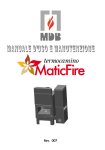
1
EN USE AND INSTALLATION MANUAL COD.8901113500 1. GENERAL INFORMATION ........................................................................................................... 4 1.1. 1.2. 1.3. 1.4. Symbols used in this manual .................................................................................................... 4 Proper appliance use ............................................................................................................... 4 Information to be provided to the user ..................................................................................... 5 Technical data label ................................................................................................................ 6 2. GUARANTEE TERMS .................................................................................................................... 7 2.1. 2.2. 2.3. 2.4. 2.5. 2.6. 2.7. 2.8. Warnings ................................................................................................................................ 7 Exclusions............................................................................................................................... 7 Additional clauses: .................................................................................................................. 8 Liability................................................................................................................................... 8 Court with jurisdiction ............................................................................................................. 8 Liability exclusion .................................................................................................................... 8 Service call ............................................................................................................................. 9 Installation standards .............................................................................................................. 9 3. TECHNICAL SPECIFICATIONS AND DIMENSIONS ................................................................... 10 3.1. 3.2. 3.3. 3.4. 3.5. 3.6. 3.6.1. 3.7. Technical specifications ......................................................................................................... 10 Description of the Variomatic boiler ........................................................................................ 11 Technical data ...................................................................................................................... 12 Main components .................................................................................................................. 13 Dimensions ........................................................................................................................... 14 Information on using pellets .................................................................................................. 15 Basic fuel requirements ......................................................................................................... 15 Pellet loading ........................................................................................................................ 16 4. INSTALLATION INSTRUCTIONS ............................................................................................... 17 4.1. 4.2. 4.3. 4.4. 4.4.1. 4.4.2. General warnings .................................................................................................................. 17 Packaging ............................................................................................................................. 18 Boiler room ........................................................................................................................... 18 Connection to the flue pipe .................................................................................................... 18 Roof outlet via an external steel flue pipe ............................................................................... 20 Roof outlet along a traditional flue pipe .................................................................................. 21 5. SYSTEM INSTALLATION PROCEDURE ...................................................................................... 22 5.1. 5.2. 5.2.1. 5.3. 5.3.1. 5.4. 5.4.1. 5.5. 5.5.1. Installation ........................................................................................................................... 22 Connecting the hydraulic system ............................................................................................ 23 Hydraulic diagram ................................................................................................................. 25 Cleaning the system .............................................................................................................. 25 Filling of the system .............................................................................................................. 26 Electrical connections ............................................................................................................ 26 General warnings .................................................................................................................. 26 Settings to implement before the first start-up ........................................................................ 27 Wiring diagram of the hot water pellet boiler .......................................................................... 28 6. ADJUSTING THE BOILER .......................................................................................................... 29 6.1.1. 6.1.2. 6.1.3. Nominal operating mode of the boiler..................................................................................... 29 Shutting down the pellet boiler for hot water production. ........................................................ 29 Shutting down the boiler. ...................................................................................................... 30 7. CONTROL PANEL DISPLAY ....................................................................................................... 31 7.1. Control panel logic ................................................................................................................ 31 8. MENU STRUCTURE .................................................................................................................... 32 8.1. 8.2. 8.2.1. Hour/minutes adjustment ...................................................................................................... 33 Settings Menu ....................................................................................................................... 33 Language ............................................................................................................................. 33 8.2.2. 8.2.2.1. 8.2.3. 8.2.4. 8.2.5. 8.2.6. 8.2.7. 8.2.8. 8.2.9. 8.2.10. 8.2.11. 8.2.12. 8.2.13. 8.3. 8.4. 8.5. 8.5.1. 8.5.2. 8.6. ECO mode ............................................................................................................................ 34 Enabling/disabling ECO mode ............................................................................................ 34 Lighting ................................................................................................................................ 35 Tones (Panel display: ON-OFF) .............................................................................................. 35 °C/°F ................................................................................................................................... 35 Recipe selection procedure .................................................................................................... 35 Smoke Blower Offset ............................................................................................................. 35 Puffer / EC Pump .................................................................................................................. 35 Temperature On Pump .......................................................................................................... 36 AUX Off ............................................................................................................................ 36 Load Pellet (ON-OFF – only shown with the boiler off) ......................................................... 36 Cleaning ........................................................................................................................... 36 Start Pump ....................................................................................................................... 37 Adjusting the water temperature in the boiler ......................................................................... 37 Adjusting the maximum flame level ........................................................................................ 37 First start-up ......................................................................................................................... 38 Start-up/shutdown from the control panel .............................................................................. 38 Note regarding first start-up .................................................................................................. 38 Connecting the room thermostat or storage tank thermostat ................................................... 39 9. SAFETY DEVICES ...................................................................................................................... 40 9.1. 9.2. Alarm signals ........................................................................................................................ 41 Silencing alarms .................................................................................................................... 42 10. TROUBLESHOOTING ............................................................................................................... 43 11. CLEANING AND MAINTENANCE .............................................................................................. 45 11.1. 11.2. 11.3. 11.4. 11.4.1. 11.4.2. Instructions for inspection and maintenance ........................................................................... 45 Cleaning the exchanger and compartment underneath the brazier ........................................... 46 Variomatic unscheduled maintenance ..................................................................................... 46 Cleaning procedure ............................................................................................................... 47 Removing ash from the surfaces of the heat exchanger ....................................................... 47 Recommendations and obligations ..................................................................................... 56 red VARIOMATIC USE AND INSTALLATION MANUAL Chapter 1 page. 4 General information The user is NOT permitted to service this boiler. The manufacturer cannot be held liable for personal injury, harm to animals or property damage resulting from failure to observe the instructions contained in the manuals supplied with the boiler. 1. GENERAL INFORMATION 1.1. Symbols used in this manual When reading this manual, pay particular attention to the parts marked with symbols. These symbols are used to give the following warnings: DANGER! Serious risk to safety and to life 1.2. CAUTION! Potentially hazardous situation for the product and the environment NOTE! Recommendations for users Proper appliance use The instruction manual is an integral and essential part of the product and must be kept by the user or system manager. Read the warnings contained in the manual carefully as they provide important information about safe installation, use and maintenance. Keep the manual in a safe place for future reference. Installation and maintenance must be performed in compliance with the standards in force, according to the manufacturer's instructions and by qualified personnel trained in accordance with the law. Professionally qualified personnel includes anyone with the specific technical skills required in the industry, spanning components for civil heating systems, domestic hot water production and the maintenance thereof. Such personnel must have the qualifications envisaged by the applicable laws in force. Incorrect installation or improper maintenance may cause personal injury, harm to animals or property damage. The manufacturer cannot be held liable for these damages. Before carrying out any cleaning or maintenance operations, disconnect the appliance from the mains power supply using the system switch and/ or the relevant external components. Do not obstruct the terminals of intake/ outlet ducts. If the appliance has a fault and/ or is not operating correctly, switch the appliance off and do not make any attempt to repair it or service it directly. Contact only legally qualified staff. Any repairs to products must be carried out only by staff authorised by RED, using only original parts. Failure to observe the above recommendations may compromise the safety of the appliance. To guarantee the efficiency of the appliance ensure that it functions correctly, it is vital that qualified personnel performs annual maintenance. Should you decide not to use the appliance, make safe any parts likely to cause potential sources of hazards. General information Technical dept. - All rights reserved - Reproduction prohibited red VARIOMATIC USE AND INSTALLATION MANUAL Chapter 1 page. 5 If the appliance is sold or transferred to a new owner or the owner moves, leaving the appliance in situ, always ensure that the manual is kept with the appliance so that it can be consulted by the new owner and/ or installer. For all appliances with optionals or kits (including electrical kits) use only original accessories. This appliance must be used only for the use expressly intended. Any other use is to be considered incorrect and therefore dangerous. The Variomatic device has been built according to the latest technologies and in accordance with the applicable technical safety regulations. Nonetheless, incorrect use of the appliance may result in hazards for users and other persons or may damage the appliance or other objects. The appliance is intended for the operation of hot water heating systems. Appliance use in accordance with the envisaged purposes includes scrupulous observance of the instructions provided in this manual. 1.3. Information to be provided to the user Before installing the appliance, wash all of the system pipes thoroughly to remove any residues that may impede the appliance from operating correctly. During installation, you must inform the user that: a. In the event of water leaks, they must shut off the water supply and advise the technical assistance department as soon as possible. b. The operating pressure of the system must be checked regularly. If the boiler is not used for a long period of time, it is recommended that you have the technical assistance department carry out at least the following operations: o Turning the master switch to the 0 position o Closing the water taps on both the heating system and the DHW system o If there is a risk of freezing empty the heating system and DHW system. General information Technical dept. - All rights reserved - Reproduction prohibited red VARIOMATIC USE AND INSTALLATION MANUAL Chapter 1 page. 6 CAUTION! Installation, adjustment and maintenance of the appliance must be performed by professionally qualified staff in accordance with the standards and provisions in force. Incorrect installation may cause damage to persons, animals and property for which the manufacturer cannot be held liable. DANGER! NEVER attempt to carry out maintenance work or repairs on the boiler on your own initiative. All servicing must be carried out by professionally qualified staff. You are advised to take out a maintenance contract. Deficient or incorrect maintenance may compromise the operating safety of the appliance and cause damage to persons, animals and property. The manufacturer cannot be held liable for these damages. Modifications to parts connected to the appliance Do not modify the following parts: The boiler Air, water and electrical current lines The flue, safety valve and heating water outlet pipe The structural elements that influence the operating safety of the device Caution! Only use suitable fork wrenches (open-ended wrenches) to tighten and loosen the screw joints. Improper use and/ or unsuitable tools may cause damages (e.g. water leaks). Explosive and highly flammable substances Do not use or deposit explosive or highly flammable materials (e.g. petrol, paints, paper) in the area where the appliance is installed. 1.4. Technical data label The technical data label is adhesive and is applied to the rear of the boiler body. The serial number of the boiler is shown on a label rivetted to the body (upper left-hand side). This label is visible when removing the top. General information Technical dept. - All rights reserved - Reproduction prohibited red VARIOMATIC USE AND INSTALLATION MANUAL Chapter 2 page. 7 2. GUARANTEE TERMS The Manufacturer guarantees the product, with the exception of parts subject to normal wear specified below, for two years from the date of purchase, provided that proof of purchase is supplied in a document specifying the name of the retailer and the date the sale was made and that the completed guarantee certificate was sent within 8 days of said purchase. The product must also be installed and tested by a specialised fitter and in accordance with the detailed instructions provided in the instruction manual that accompanies the product. The guarantee covers the replacement or free repair of parts recognised as being faulty at source due to manufacturing defects. 2.1. Warnings Installation, electrical connection, functional check and maintenance of this appliance must only be performed by qualified or authorised personnel. This appliance must not be used by anyone (including children) with reduced physical, sensory or mental skills and with little experience and knowledge, unless they are supervised or have been instructed to use the appliance by the person in charge of its safety. The guarantee applies, provided that: 1. The boiler is installed, in accordance with the applicable standards in force and the instructions provided in the product use, maintenance and installation manual, by legally qualified staff (Italian Ministerial Decree no.37 of 22nd January 2008); 2. The customer holds the documentation certifying its suitability in all parts: a. INSTALLATION REPORT – filled in by the fitter b. TEST REPORT and GUARANTEE APPLICATION – filled in by an authorised serviceman 3. The guarantee is valid from the date on which the boiler is first started up (which must be indicated in the boiler manual) or from the invoice date. This documentation must be presented to the authorised service centre in the event of servicing. 2.2. Exclusions The guarantee does not cover any parts found to be faulty due to negligence or inappropriate use, incorrect maintenance, or installation not performed in compliance with the manufacturer's instructions. The manufacturer will not be held liable for any damage which may - either directly or indirectly - be caused to persons, animals or property resulting from failure to observe all the instructions provided in this manual and, specifically, concerning the warnings regarding installation, use and maintenance of the appliance. The guarantee is not valid if: 1. The terms for implementing the guarantee were not observed. 2. Installation was not performed in observance of the applicable standards in force and the instructions provided in the use, maintenance and installation manual. The guarantee does not cover: 1. Damage caused by atmospheric, chemical or electrochemical agents, incorrect product use, natural disasters, electrical shocks, fires, faults in the electrical system, modifications to or tampering with the product and/ or other causes not ensuing from product manufacturing 2. Damage caused by normal corrosion 3. Damage relating to the combustion chamber Guarantee Technical dept. - All rights reserved - Reproduction prohibited red VARIOMATIC USE AND INSTALLATION MANUAL Chapter 2 page. 8 4. Damage to seals, claddings, painted/ chromed parts, handles and electrical wires 5. Damage to masonry work 6. Damage to parts of the system for the production of DHW not supplied by RED 7. Damage to the heat exchanger if a suitable condensation-proof circuit is not set up to guarantee a minimum boiler return temperature of at least 55 °C. 8. Servicing for product calibration or adjustments 9. Incorrect or negligent use. 10. All damage caused by transport. We therefore advise you to check goods carefully upon receipt, notifying your retailer immediately of any damage and noting this on the delivery note and on the copy retained by the carrier. Please contact your retailer and/ or local importer in the event of product failure. RED will not be held liable for any damage which may - either directly or indirectly - be caused to property, or personal injury or harm to animals ensuing from failure to observe all the instructions provided herein and the applicable regulations regarding installation, use and maintenance of the appliance. The parts replaced will be guaranteed for the remaining guarantee cover period starting from the original date of purchase of the product. 2.3. Additional clauses: If faulty or malfunctioning parts are detected during normal product use, these will be replaced free of charge ex retailer who made the sale or ex our local technical service centre. For products sold abroad, the same circumstances will again result in free replacement, ex our retailer, with the exception of specific conditions agreed upon at the time of negotiations with the foreign distributor. In the case of replaced parts, the guarantee will not be extended. No damages are awarded for the product downtime period. This is the only applicable guarantee and no-one is authorised to provide any other guarantees in the name of or on behalf of RED. 2.4. Liability RED will not pay any compensation for direct or indirect damage caused by or dependent upon the product. 2.5. Court with jurisdiction In the event of any controversy, the court with jurisdiction is the Court of Pordenone (Italy). 2.6. Liability exclusion The manufacturer is unable to supervise the observance of the instructions provided in this manual, nor the conditions and methods of installation, operation, use and maintenance of the product. Incorrect installation could cause damage and endanger persons. Consequently, we cannot be held in any way liable for losses, damage or costs ensuing from incorrect installation, incorrect functioning and improper use and maintenance or in any way connected to the latter. Similarly, we will not be held in any way liable for any violations of patents or third party rights ascribable to the use of this product. The Manufacturer reserves the right to make any changes to the product, technical specifications or to the manual without notice. If hazard-free operation is no longer possible (for instance, due to visible damage), turn off the appliance immediately. Guarantee Technical dept. - All rights reserved - Reproduction prohibited red 2.7. VARIOMATIC USE AND INSTALLATION MANUAL Chapter 2 page. 9 Service call The service call must be made to the retailer or service centre. The manufacturer cannot be held liable if the product and any of its accessories are used incorrectly or modified without authorisation. Only original spare parts must be used for replacements. 2.8. Installation standards The Variomatic boiler is designed to run on wood pellets. It must be installed according to the provisions of the following standards: Italian Law Decree no. 93 of 25 th February 2000 Implementation of Directive 97/23/EC (P.E.D.) on the subject of pressure equipment. SCOPE OF APPLICATION liquid fuel (naphtha, gas oil, fuel oil) and solid fuel operated appliances. ITALIAN LAW of 5th March 1990 no. 46 and related applicative regulations Italian Ministerial Decree no. 447 of 6th December 1991 (and subsequent amendments) and Italian Ministerial Decree no. 37 of 22nd January 2008 System safety standards SCOPE OF APPLICATION: without limits to heat potential. Standard UNI 10847 of 03/2000 Single flue systems for liquid and solid fuel generators. Maintenance and control. Guidelines and procedures. SCOPE OF APPLICATION: liquid and solid fuel operated systems. ITALIAN LAW of 9th January 1991 No. 10 and related applicative regulations Italian Ministerial Decree no. 412 of 26th August 1993 (and subsequent amendments), Italian Ministerial Decree no. 551 of 21 st December 1999. Regulations specifying amendments to Italian Presidential Decree 412 on the subject of planning, installing, running and servicing heating systems in buildings for the purposes of limiting energy consumption. SCOPE OF APPLICATION: without limits to heat potential. ITALIAN LAW NO. 186 of 01.03.1968 Installation standard CEI 64-8 / II ed. Electrical utility systems at a nominal voltage of no more than 1000 V in alternating current and 1500 V in direct current. Installation standard CEI 64-8 / I ed. Electrical utility systems in buildings intended for residential and similar purposes. Standard UNI 10683 of 09/2005 Systems running on wood or other solid biofuels. Installation requirements SCOPE OF APPLICATION: systems running on wood or other solid biofuels with a heat decomposition power of the combustion chamber below 35 kW. The installation procedure for the system consisting of a pellet boiler and pellet burner requires the scheme for the heating system, prepared in accordance with the standards and local recommendations in force, as follows: For the heating system - EN 303-5/2000 - "Boilers for heating. Part 5: Heating boilers for solid fuels, hand and automatically stocked, nominal heat output of up to 300 kW. Terms, requirements, tests and marking". Local requirements for the flue connection. Local requirements for fire-prevention standards. For the power circuit - EN 60335-1/1997- “Safety of electrical appliances for domestic and similar use, Part 1 – General requirements”. This appliance must be installed in accordance with the provisions of the applicable standards in force in the country of installation of the boiler. Guarantee Technical dept. - All rights reserved - Reproduction prohibited red VARIOMATIC USE AND INSTALLATION MANUAL Chapter 3 page. 10 3. TECHNICAL SPECIFICATIONS AND DIMENSIONS 3.1. Technical specifications The Variomatic mod. heat generator is a steel boiler fuelled by wood pellets with a vacuum combustion chamber. Heat exchanger welded with steel plates to heat the water in the circuit Combustion gas fan Fresh air supply fan Mechanism to remove ash from the burner - removes ash residues from the burner grille Hopper for daily fuel with a capacity of approximately 130 kg. Programmable operating module that controls the operation of the appliance. This module can be adjusted to the specific requirements of the individual heating system as well as for the characteristics of the fuels. Container for ash residues with a capacity of approximately 5 kg. Semi-automatic, manually enabled system for ash removal (this system removes ash deposited on the inner surfaces of the pipes in the connective sections of the boiler) Automatic fuel ignition system Automatic system for removing ash from the burner Automatic system with fuel supply auger Automatic operation of the appliance. The hot water boiler can be connected to a programmable room thermostat that guarantees maximum heat comfort and reduced fuel consumption. The appliance uses solid biomasses in the form of pellets (wood pellets) as fuel. The ash content of these pellets is above the limits defined by the following standards: ENplus (EN 14961-2:2010), ONORM M7135, DIN 51731 DINPlus. High efficiency. Low content of polluting agents in the combustion gasses. The operating control module can activate the operation of an additional, external fuel supply system that feeds the fuel from an external hopper to the relevant integrated hopper. Maintenance and very simple servicing procedures. Low management costs. Technical specifications Technical dept. - All rights reserved - Reproduction prohibited red 3.2. VARIOMATIC USE AND INSTALLATION MANUAL Chapter 3 page. 11 Description of the Variomatic boiler The heat exchanger of the boiler complies with the operating requirements of this type of appliance. These requirements are defined in operating standard EN 303-5/2004 - "Boilers for solid fuels, hand and automatically stocked, with heat output of up to 300 kW. Terms, requirements, tests and marking". The appliance consists of: A special burner with grille designed to supply fuel horizontally. The heat exchanger with a welded structure with carbon steel plates and steel pipes. The lower part of the exchanger is designed as a combustion chamber. The burner is installed in this chamber and carries out an efficient combustion process. An ash tray positioned in the lower part of the combustion chamber, underneath the burner. A fuel hopper fitted beside the heat exchanger of the boiler. An auger separator for the fuel is located underneath the hopper. This also acts as a fuel metering unit. The auger separator is followed by a horizontal conveyor auger. The fuel metering unit prevents the "back-fire" process, in other words; the ignition of the fuel in the hopper by the hot combustion gasses in the auger duct. This may occur in fault situations. The fan fitted on the air duct of the burner. The fan is equipped with an adjustable fin to set the flow of air. Flow and return water connections equipped with an internal screw thread, positioned in the rear part of the heat exchanger. The outlet connection equipped with a G½ diameter screw thread, positioned in the lower, rear part of the heat exchanger. A suitable discharge valve must be connected. A smoke outlet duct positioned in the upper, rear part of the heat exchanger (after the combustion gas fan). Covers insulated with mineral wool plates that ensure low heat loss in the surrounding environment. Technical specifications Technical dept. - All rights reserved - Reproduction prohibited red 3.3. VARIOMATIC USE AND INSTALLATION MANUAL Chapter 3 page. 12 Technical data PARAMETERS NOMINAL HEAT OUTPUT OPERATING RANGE (min-max) SOLID FUEL USED WOOD PELLET CONSUMPTION RATE (min-max) FRESH AIR RATE REQUIRED FOR EFFICIENT COMBUSTION PROCESS AND BOILER OPERATION DIMENSIONS KW KW WOOD PELLETS kg/h kg/h VALUES 30 9-30 m3/h 42-50 MASS OF SMOKE AVERAGE WOOD PELLET CONSUMPTION RATE (the appliance operates in a nominal heating system) HEATING EFFICIENCY (min-max) EXCESS AIR RATIO TEMPERATURE OF COMBUSTION GASES AT NOMINAL HEAT OUTPUT SOLID FUEL RESIDUE g/s kg/h 18,6 4.5 % ʎ °C 91,1-93,4 1.4-1.6 140-150 ASH WEIGHT WATER TANK CAPACITY FUEL TANK CAPACITY kg dm3 dm3 The quantity depends on the ash contents of the raw fuel, as well as on the operating conditions 460 95 198 kg 130 KG PELLET mm bar °C 1515 x 850 x 1365 3 2 80 °C 60 Pa G G mm VA - 20-30 1 ½” ½” 150 230 V – 50 Hz VA 120+250 (at the start-up process) IP20 BOILER DIMENSIONS (WxDxH) CLASS (COMPLIANT WITH EN303-5) MAXIMUM SYSTEM PRESSURE RECOMMENDED TEMPERATURE FOR CIRCULATING WATER RECOMMENDED MINIMUM TEMPERATURE OF RETURN WATER DRAUGHT CONNECTIONS SYSTEM FLOW/ RETURN SYSTEM DRAIN OFF SMOKE OUTLET POWER SUPPLY ELECTRICAL CAPACITY ELECTRICAL PROTECTION 2,1-6,8 50-60 The results in the table have been obtained using pellets certified according to standards DIN51731, DINplus and ÖNORM M7135 Emissions according to UNI EN 14785 Output according to UNI EN 14785 Technical specifications Technical dept. - All rights reserved - Reproduction prohibited red 3.4. Main components Chapter 3 VARIOMATIC USE AND INSTALLATION MANUAL Heat exchanger of the boiler page. 13 Fuel hopper Fuel metering unit Fuel conveyer auger System for the removal of ash from the boiler Combustion gas outlet duct Technical specifications External fuel flow hole Technical dept. - All rights reserved - Reproduction prohibited red 3.5. VARIOMATIC USE AND INSTALLATION MANUAL Chapter 3 page. 14 Dimensions Technical specifications Technical dept. - All rights reserved - Reproduction prohibited red 3.6. VARIOMATIC USE AND INSTALLATION MANUAL Chapter 3 page. 15 Information on using pellets The main characteristic of the boiler is that it burns a natural fuel (pellets) obtained ecologically from wood industry waste (sawdust, chips). The sawdust and chips obtained from wood machining are first suitably cleaned and dried, and then compacted at very high pressure to produce small nuggets of pure wood, i.e. pellets. It is an absolutely ecological fuel since it does not use any glue to keep it compact. Indeed, the compact nature of pellets over time is ensured by a natural substance found in wood: jet (or lignite). Each pellet can vary in length and thickness, between 1÷3 cm in length and 6÷8 mm in diameter respectively. The main characteristics of pellets are their low humidity (below 12%). Their high density (approx. 600 kg/m3) and regular compact texture give this type of fuel properties of high calorific value (NCV 4100÷5000 kcal/kg). In order to prolong the life cycle of the boiler, RED recommends the use of good quality pellets. The pellets to be used to power the boiler must have high quality characteristics, such as those set out in standards DIN 51731 and ÖNORM M7135. It is vital that you check regularly that there are some pellets left inside the tank to avoid them running out completely and therefore the boiler shutting off. WARNINGS The use of poor quality pellets or of any other inappropriate material could damage certain components of the boiler and jeopardise its correct functioning: this could render the guarantee null and void, and relieve the manufacturer of any liability. RED encourages users to use pellets which comply with the characteristics set out herein above. 3.6.1. Basic fuel requirements The fuel, in the form of pellets, must be dry. The appliance manufacturer recommends that the fuel is kept in dry, well aired premises. It is strictly forbidden for the fuel to be kept near the system (either the boiler or the burner); the minimum safety clearance between the fuel and the appliance is 400 mm. The system manufacturer recommends an optimal distance between the boiler and the fuel tank of at least 1000 mm. It is advisable for the fuel to be kept in a room close to the one where the boiler is installed. The fire prevention regulations must be taken into consideration during the system installation procedure and during the fuel storage. It is also recommended that a fire extinguisher be fitted in a safe and easily accessible place. Technical specifications Technical dept. - All rights reserved - Reproduction prohibited red 3.7. VARIOMATIC USE AND INSTALLATION MANUAL Pellet loading Chapter 3 page. 16 PELLET TANK OPEN THE TANK COVER EMPTY THE PELLETS INTO THE TANK It is important to check regularly that there are still pellets inside the tank to avoid them running out completely and the boiler consequently shutting off. WARNINGS The use of poor quality pellets or of any other inappropriate material could damage certain components of the boiler and jeopardised its correct functioning: this could render the guarantee null and void, and relieve the manufacturer of any liability. RED encourages users to use pellets that comply with the characteristics set out in the standards in force. Technical specifications Technical dept. - All rights reserved - Reproduction prohibited red VARIOMATIC USE AND INSTALLATION MANUAL Chapter 4 page. 17 4. INSTALLATION INSTRUCTIONS 4.1. General warnings o This boiler must only be used for the use expressly intended. Any other use is to be considered incorrect and therefore dangerous. o This boiler is used to heat water at a temperature lower than boiling point at atmospheric pressure. o These appliances are designed solely for installations in suitable rooms or technical premises. Consequently, these appliances cannot be installed and operated outdoors. Outdoor installation could lead to malfunctions and hazards. For outdoor installations, we advise you to choose an appliance designed specifically for this purpose. o The boiler must NOT be used by children or unassisted persons with limited abilities. o Do NOT leave any packaging components within the reach of children or persons with limited physical, sensory or mental skills or with little experience and knowledge. o Do NOT touch the boiler while bare foot and with wet or damp body parts o The venting apertures are vital for correct combustion o After a period of inactivity, check for any obstructions before starting the boiler. o Do NOT block or reduce the size of the venting apertures of the room where the boiler is installed o Do NOT pull, detach or tamper with the electrical wires protruding from the boiler, even when the boiler is disconnected from the electricity supply. o Caution: some parts of the boiler can get very hot. You are therefore advised to wear suitable heat protection. o Do NOT modify the safety or regulating devices without the manufacturer's authorisation. o The door to the combustion chamber MUST remain shut during normal product operation o The boiler was designed to operate in any weather, yet in the case of adverse weather (strong wind, ice), the safety systems may be triggered and shut off the boiler. If this is the case, contact the service centre and do not override the safety devices. o In the event of fire in the flue pipe, call the fire brigade. o If the boiler shuts down, for reasons other than routine maintenance, call the service centre. o Before making the boiler connections, have professionally qualified staff perform the following: a) Clean all system pipes thoroughly to remove any residues or impurities that may compromise the correct operation of the boiler b) Check that the chimney flue/flue pipe has a suitable draft, is free of any kinks, and that no outlets from other appliances are introduced there. This check must be performed before connecting the boiler and the chimney flue/ flue pipe. o The appliance must be installed by a qualified fitter with the required technical and professional qualifications pursuant to Italian Law 46/90 and to Italian Ministerial Decree no. 37 of 22 nd January 2008 who, under his own responsibility, shall guarantee compliance with good practice regulations. o The boiler must be connected to a heating system and/or to a domestic hot water production network, compatibly with its performance and power. Installation instructions Technical dept. - All rights reserved - Reproduction prohibited red 4.2. VARIOMATIC USE AND INSTALLATION MANUAL Chapter 4 page. 18 Packaging The boiler is delivered on a single pallet with a wooden crate, protected by cardboard packaging. The boiler must always be handled vertically, using manual or mechanical cranes, which can lift the pallet on which it is packaged or the boiler itself directly. Take special care not to damage electrical or mechanical parts, with shocks or water sprays once the protective packaging has been removed. After removing the packaging, make sure the boiler is complete and undamaged If in doubt, contact the retailer The document envelope (inserted in the pellet tank) contains: Heating system maintenance booklet An instruction manual for installation, use and maintenance Appendix G - Technical inspection report for heating system with an output of less than 35 kW Guarantee 4.3. Boiler room Make sure the room complies with the requirements and characteristics set out in the applicable regulations in force. It is also necessary for the room to provide at least as much air as is required for regular combustion. It is therefore necessary to make holes in the walls of the room, which comply with the following requirements: Have a free cross-section of at least 6 cm2 for every 1 kW (859,64 kcal/h). The minimum crosssection of the opening must nevertheless never be less than 100 cm 2. The cross-section can also be calculated using the following ratios: S = K * Q ≥ 100 cm2 Where “S” is expressed in cm2, “Q” in kW, “K” = 6 cm2/kW 4.4. The opening must be situated at the bottom of an external wall, preferably opposite the one where the combustion gases are vented. Connection to the flue pipe For the connection of the flue outlet pipe, local and national regulations must be observed (see Standards UNI 7129 and UNI 10683). A flue pipe must comply with the following requirements: It must be made of waterproof material resistant to the temperature of the smoke and related condensation It must ensure sufficient mechanical resistance and weak heat conductivity It must be perfectly sealed, to avoid the cooling of the flue pipe itself. It must be arranged as vertically as possible Chimneys both old and new, built without observing the above specifications may be conveniently recovered by "intubating" the chimney itself. This means a metal flue shall be inserted inside the existing chimney and the space between the metal flue and the chimney shall be filed with suitable insulation. Installation instructions Technical dept. - All rights reserved - Reproduction prohibited red VARIOMATIC USE AND INSTALLATION MANUAL Chapter 4 page. 19 In order to prevent the wind from creating pressure areas around the chimney that prevail over the rising force of the combustion gases, the outlet aperture must be positioned at least 0.5 metres above any structure adjacent to the chimney itself (including the ridge of the roof) at least 8 metres away. The flue pipe must have a diameter of no less than the boiler union; for flue pipes with a square or rectangular cross-section, the internal cross-section must be increased by 10% compared to the boiler union. We recommend calculating the flue cross-section from the following report to guarantee adequate draught: S = K x P/√H S ensuing section in cm2 K reduction coefficient: 0.04 for wood and pellet P boiler output in kcal/h H height of the chimney in metres, measured from the flame axis to the outlet of the chimney into the atmosphere. When sizing the flue pipe, please take into account the actual height of the chimney in metres, measured from the flame axis t the top, decreased by: 0.50 m for every change in direction of the union duct between the boiler and the flue pipe 1.00 m for every metre of horizontal development of the union itself. We recommend the sole use of outlet ducts which are suitable for the type of fuel used. The supplier will not be held in any contractual and non-contractual way liable for damage caused by installation and usage errors and in any case due to failure to observe the instructions provided by the manufacturer of the appliance. The products of combustion of the boiler cannot be discharged in collective flue ducts. The correct installation of the flue duct is necessary to encourage the normal flow of smoke from the combustion chamber to the outside in the event of an electrical power failure. Remember that a draught of 20-30 Pa must be ensured. Below are the main characteristic traits of the flue duct according to the provisions of standards UNI 7129 and UNI 10683: The smoke outlet must be equipped with inspection valves; The minimum height of the pipe directly connected to the smoke outlet of the boiler must be between 2÷3 m; If the presence of a horizontal section is necessary, we recommend that the same is of a maximum length of 1.5 m and with a slope gradient of 3÷5% to encourage the smoke to flow away; Use of a wind-proof and rain-proof terminal to avoid changing the slight overpressure inside the flue pipe (we recommend you end the flue pipe with a horizontal section); The outlet ducting must be made with suitable materials which can withstand the products of combustion and any condensation of the same (the inspection valve can allow any condensation that has formed to be vented); The ducts must be built to ensure maximum seal against smoke (UNI 10683); We recommend you insulate the duct, especially on the outside part exposed to the weather. Installation instructions Technical dept. - All rights reserved - Reproduction prohibited red VARIOMATIC USE AND INSTALLATION MANUAL Chapter 4 page. 20 Avoid installing completely horizontal sections. The room where the heat generator is to be installed must not contain any existing or envisaged smoke suction hoods in order to avoid depressurising the setting. The air intakes must not be closed. Make sure the flue pipe is kept clean, cleaning it at least once a year. In the event of a fire in the flue pipe or duct, switch the boiler off immediately and disconnect it from the domestic electricity mains 4.4.1. Roof outlet via an external steel flue pipe One possible installation solution is to position the boiler near a perimeter wall of the home so that the smoke is discharged along an external flue pipe. Below are some provisions of standard UNI 7129 for this particular system configuration: - Always make sure there is an inspection valve to allow periodic and efficient cleaning, as well as the venting of any condensation that may have formed; - The chimney must under all circumstances be wind-proof and rain-proof; - Make sure the smoke outlet duct is suitably insulated in the section that crosses the wall. Chimney Insulate the flue pipe Soot tray It is advisable for the smoke outlet duct, if it is completely outside, to be made of double-wall stainless steel to guarantee both greater resistance to the atmospheric agents as well as the appropriate temperature of the smoke outlet. Installation instructions Technical dept. - All rights reserved - Reproduction prohibited red VARIOMATIC USE AND INSTALLATION MANUAL Chapter 4 page. 21 4.4.2. Roof outlet along a traditional flue pipe The flue smoke can also be discharged using an existing traditional flue pipe provided it is compliant to standards (see UNI 10683). Here is a brief list of the main characteristics highlighted in the standard that distinguish a good chimney: - Suitable insulation and lagging especially in the external section exposed to the atmosphere; - Constant internal cross-section (there must not be any narrower sections); - Made with material resistant to high temperatures, to the action of the products of combustion and to the corrosive action of any condensation that may form; - Prevalently vertical arrangement with deviations from the axis of no more than 45°; Soot tray accessible for inspection with possible condensation discharge It is compulsory to include a chamber for the collection of solid material and/ or any condensation, which can be inspected through an airtight door. It is compulsory to observe the provisions of standards UNI 9615 and 9731 for the sizing of the chimney cross-section and, in all cases, avoid installing ducts with a cross-section of less than 150 mm. If larger cross-sections are used a steel duct must be inserted inside the masonry duct. Direct outlet via walls is not permitted. The steel pipe must be suitably insulated with material which is resistant to high temperatures and sealed off from the external chimney. Installation instructions Technical dept. - All rights reserved - Reproduction prohibited red VARIOMATIC USE AND INSTALLATION MANUAL Chapter 5 page. 22 5. SYSTEM INSTALLATION PROCEDURE 5.1. Installation The Variomatic boiler is a heat generator that draws the combustion air required for the combustion process directly from the environment in which it is installed. For this reason (and for even more important reasons of safety for those using the boiler) the boiler must be installed in an adequately ventilated environment to ensure a constant flow of combustion air. Therefore, air inlets linked to the outside MUST be made and, in compliance with the provisions of Standard UNI 10683, must have the following characteristics: 1. A free cross-section of no less than 80 cm2; 2. Be provided as close to floor-level as possible; 3. Be suitably protected by a wire mesh or grate so that the free cross-section for air passage is not reduced; 4. Be positioned in such a way as not to be obstructed in any way. The correct supply of air can be ensured via openings into an adjoining room, provided that direct ventilation is supplied and that such a room is not a fire hazard (e.g.: store rooms, garages or warehouses) in accordance with the regulations set out in standard UNI 10683. Install the boiler in premises which do not contain appliances that do not operate in a room-sealed manner or appliances that could depressurize the room itself in relation to the outside and thereby cause problems relating to poor draught for the smoke evacuation system (UNI 10683). When checking the compatibility of the system, check whether the support surface (floor) has a sufficient load bearing capacity (in kg) for the weight of the product that it must support. If the capacity is not sufficient, adopt suitable safety measures. Also, if the floor is constructed of combustible materials (e.g. parquet) protect it by placing a strip of fireproof material underneath the boiler. This strip must be sufficiently wider than the base. The boiler must be installed horizontally and perfectly stable to reduce any vibrations and noise (to level the boiler act on the feet installed beneath the boiler). The Variomatic boiler must be installed in a compartment with a height NOT LESS than approximately 1865 mm. The minimum measurements of the boiler room must be approximately 2300 x 2300 h 1865, divided as shown in the diagram: 1000 mm from the wall to the front of the boiler 400 mm from the wall to the rear of the boiler 500 mm from the right side of the boiler to the wall; measurement required for fuel filling 300 mm from the left side of the boiler to the wall to ensure maintenance of the outlet gas fan 500 mm from the top of the boiler to the ceiling to ensure access to the fuel filling tank. System installation procedure Technical dept. - All rights reserved - Reproduction prohibited red 5.2. VARIOMATIC USE AND INSTALLATION MANUAL Chapter 5 page. 23 Connecting the hydraulic system When installing the boiler all applicable national and regional standards in force as well as those relating to the province and commune of the area must be adhered to. There are two types of system: open vessel system closed vessel system (foreseen for the Variomatic boiler) OPEN VESSEL SYSTEM System in which the water contained in it is in direct or indirect contact with the atmosphere, equipped with an open expansion vessel located at the top of the system. The vessel is in contact with the atmosphere via an associated vent pipe. CLOSED VESSEL SYSTEM FOR AUTOMATIC FILL APPLIANCES System in which the water contained in it is not in direct or indirect contact with the atmosphere. The closed vessel system is equipped with an expansion vessel. Closed systems must be equipped with: a safety valve (not included) a circulator control thermostat A temperature indicator A pressure indicator An automatic heat regulation switch System installation procedure Technical dept. - All rights reserved - Reproduction prohibited red Chapter 5 VARIOMATIC USE AND INSTALLATION MANUAL page. 24 An automatic heat shut-off switch (shut-off thermostat) A circulation pump (not included) An expansion vessel (not included) 171 111 124 ” 15 Ø 1 G 0 2 1/ B G 1 1/ 2” 1365 A C G 108 1 1/ 2” D 72 1515 A B C D COMBUSTION GAS OUTLET PIPE FEMALE G 1½” SYSTEM FLOW CONNECTION FEMALE G 1½” SYSTEM RETURN CONNECTION FEMALE G ½” OUTLET CONNECTION System installation procedure Technical dept. - All rights reserved - Reproduction prohibited red VARIOMATIC USE AND INSTALLATION MANUAL Chapter 5 page. 25 5.2.1. Hydraulic diagram Solar control unit Solar panel Solar pump station Safety valve Thermal mixer High temperature direct circuit Safety valve Bollitore Pipe in Tank cylinder Pipe in tank The diagram shows an example of a hydraulic connection equipped with an open expansion vessel (obligatory), mixer valve and heat accumulator. 5.3. Cleaning the system Connections MUST be easy to disconnect by means of swivel pipe unions. Fit suitable cut-off gate valves on the heating system piping. Caution: A safety valve must be fitted on the system. To prevent hazardous corrosion of the heating system and the formation of scaling and deposits, it is of the highest importance to wash the system prior to installation, in accordance with standard UNI-CTI 8065, using appropriate products such as Sentinel X300 (new systems), X400 and X800 (old systems) or Fernox Cleaner F3. Full instructions are provided with the products. However, for further details contact the manufacturer directly: SENTINEL PERFORMANCE SOLUTIONS LTD or FERNOX COOKSON ELECTRONICS. After washing the system, you are advised to use inhibitors such as Sentinel X100 or Fernox Protector F1 to protect the system from corrosion and deposits. Is it important to check the concentration of the inhibitor after each modification to the system and each maintenance check, according to the specifications provided by the manufacturers (relevant tests are available from retailers). The outlet from the safety valve must be connected to a collection funnel to channel any discharge if servicing is carried out. If the heating system is at a higher level than the boiler, you must install cut-off cocks on the system flow/return pipes. These cocks are provided in the optional kits. System installation procedure Technical dept. - All rights reserved - Reproduction prohibited red VARIOMATIC USE AND INSTALLATION MANUAL Chapter 5 page. 26 Caution: Failure to wash the heating system and add a suitable inhibitor shall invalidate the device guarantee. 5.3.1. Filling of the system Before connecting the boiler, it is good practice to allow water to flow through the pipes to eliminate any foreign bodies that may compromise correct operation of the appliance. The appliance should be filled slowly to allow any air bubbles to be released through the appropriate vents within the heating system. In closed circuit heating systems, the cold filling pressure of the system must correspond to the expansion vessel pre-inflation pressure. In any case, the pressures must not be less than the height of the static column of the system (for example, a 5-metre static column requires a minimum vessel pre-filling pressure and system filling pressure of 0.5 bar). Supply water characteristics The water supply of the heating circuit must be treated in accordance with standard UNI-CTI 8065. You are advised to remember that even small deposits of a few millimeters in thickness have low heat conductivity and cause the walls of the boiler to heat up significantly, leading to serious problems. TREATMENT OF WATER USED IN THE HEATING SYSTEM IS ABSOLUTELY ESSENTIAL IN THE FOLLOWING CASES: Greatly expanded systems (with high water contents) Frequent introduction of reintegration water into the system. If the system must be partially of fully emptied. 5.4. Electrical connections 5.4.1. General warnings The electrical safety of the system is only ensured when the same is correctly connected to an efficient earthing system, built in accordance with the provisions of the applicable safety standards: the piping of the gas, plumbing and heating systems are absolutely not suitable. It is important that you check this fundamental safety requirement; if in doubt, ask for the electrical system to be checked thoroughly by professionally qualified staff, since the boiler manufacturer is not liable for any damage caused by failure to earth the system. Have professionally qualified staff check that the electrical system is suitable for the maximum electricity consumption of the system, ascertaining specifically that the cross-section of the system cables is suitable for the power consumption of the utilities. The use of adaptors, multiple sockets and/ or extension cables is not permitted for the general power supply to pumps and other utilities on the electrical network. Certain fundamental rules must be observed when using any components that use electricity. These rules are as follows: do not touch the appliance with wet and/ or damp body parts and /or while bare foot; do not pull on electrical cables; do not leave the appliance exposed to weather (rain, sunshine, etc.) unless it is designed specifically for this purpose; Do not allow children or inexperienced persons to use the appliance.. System installation procedure Technical dept. - All rights reserved - Reproduction prohibited red VARIOMATIC USE AND INSTALLATION MANUAL Chapter 5 page. 27 Connection to 230V electricity supply The installation of the electrical accessory components of the boiler requires electrical connection to a mains at 230 V – 50 Hz: This connection must be made according to best practice in accordance with the applicable CEI standards. Danger! The electrical connection must only be performed by an authorised technician. Before making the connections or performing any servicing of electrical parts, always disconnect the electricity supply and make sure it cannot be re-established inadvertently. Remember that an easily-accessed bipolar switch with a minimum contact opening of 3 mm must be installed on the electrical power supply line to the boiler, in order to facilitate and speed up any maintenance operations. The power supply cable must only be replaced by authorised technical staff. Failure to observe the above recommendations may compromise the safety of the appliance. 5.5. Settings to implement before the first start-up Once the power supply cable at the rear of the boiler is connected, turn the switch - again at the rear - to position (I). The LED in the switch will light up. The switch at the rear of the boiler powers the system. The boiler remains turned off and the panel shows the initial screen with the word OFF. Pressing any key will display a screen with the word MENU. System installation procedure Technical dept. - All rights reserved - Reproduction prohibited System installation procedure 11. PUMP max 230V 3A 12. SMOKE BLOWER 13. AUTOMATIC CLEANER 14. ROOM THERMOSTAT WITH CLEAN CONTACT 15. DOMOTIC 16. EXTERNAL AUX SIGNAL (N.C., max 230V 3A) 17. FAULT SIGNAL (N.A., max 230V 3A) 2. SMOKE SENSOR 3. POWER SUPPLY 4. IGNITER 5. SMOKE BLOWER FAN 6. GEARED MOTOR 7. WATER TEMPERATURE OVERLOAD CUT-OUT 8. PELLET TEMPERATURE OVERLOAD CUT-OUT 9. SMOKE BLOWER FAN REV CONTROL 10. WATER TEMPERATURE SENSOR 1. CONTROL PANEL red VARIOMATIC USE AND INSTALLATION MANUAL Chapter 5 page. 28 5.5.1. Wiring diagram of the hot water pellet boiler Technical dept. - All rights reserved - Reproduction prohibited red VARIOMATIC USE AND INSTALLATION MANUAL Chapter 6 page. 29 6. ADJUSTING THE BOILER 6.1.1. Nominal operating mode of the boiler. The nominal heat load of the appliance must be used to carry out the "tests while warm". This is a check of the entire heating system in accordance with the standards in force for an operating heating system (for example; checking whether there are leaks in the circulating water). N.B.: Check that the temperature entering the boiler is above 60 oC. If the temperature is low, water vapour condensation may form on the inner surfaces of the heat exchanger (note that water vapour is one of the end products of the combustion process and is also present in the combustion gasses of the boiler). CAUTION! the air flow is crucial for optimal function of the combustion process, which occurs in the burner, and for efficient operation of the boiler in general. When air flow is below the optimum rate, this insufficiency causes incomplete combustion of the fuel since the amount of oxygen supplied is not sufficient. Unsatisfactory results are also produced when air flow is above the optimal rate. This is because the excess air brings the fuel to a low temperature, causing incomplete combustion of the volatile gasses in the fuel emitted by the combustion process. 6.1.2. Shutting down the pellet boiler for hot water production. To shut down the boiler, press key B on the appliance interface panel. If the boiler is left unused for a relatively short period of time, you are advised to remove the ash deposited on the heating surfaces. These surfaces are within easy reach of the heat exchanger. CAUTION! if the system is left unused for a long period of time you must clean the heat exchanger thoroughly to remove all the ash deposited. The ash deposited on the metal surfaces has a corrosive effect on carbon steel surfaces. Consequently, this shortens the life span of the main modules of the boiler; the heat exchanger and burner. It is compulsory to have maintenance procedures and preventive appliance checks carried out only by trained service staff. The appliance must also be thoroughly cleaning at the end of every heating season. If these procedures are observed, the boiler is sure to have a long life span, together with high efficiency and reliability. Adjusting the boiler Technical dept. - All rights reserved - Reproduction prohibited red VARIOMATIC USE AND INSTALLATION MANUAL Chapter 6 page. 30 6.1.3. Shutting down the boiler. • Emergency boiler shutdown. While the boiler is operating, emergency situations may arise, prompting the boiler to enter alarm/ fault mode. Before carrying out any intervention refer to the information displayed on the control module display. Once the cause of the alarm has been identified, take suitable measures to return the boiler to normal operating conditions. CAUTION! in the event of an emergency situation arising (boiler overheating) the emergency thermostat will activate, the control module display will show a relevant message and the warning light will come on. Should this event occur, the boiler must be cooled and the cause of the overheating must be checked. Preventative measures must then be adopted. The emergency thermostat must be manually reset by unscrewing the protective cap and pressing the stem until the thermostat switch is reset (you should hear a "click"). Then screw the cap back on. Adjusting the boiler Technical dept. - All rights reserved - Reproduction prohibited red VARIOMATIC USE AND INSTALLATION MANUAL Chapter 7 page. 31 7. CONTROL PANEL DISPLAY 7.1. Control panel logic Below is some useful information to understand the logic for browsing and using the control panel. The brightness of the control panel is turned off after approximately 30” if the keyboard is left unused. To turn the backlighting back on, simply press any of the panel buttons. The first screenshot displays the boiler operating status (ON, OFF, START-UP, SHUTDOWN...). It also shows the current time and the temperature of the water measured in the boiler. If you press any of the 4 keys surrounding the display (C D E F), you will enter the boiler operation set-up screen (maximum flame level, boiler set temperature). In this menu, the 4 keys surrounding the display assume "dedicated" functions, i.e. they are directly referred to the corresponding wording shown in the 4 corners of the display (e.g. the top right wording refers to key D). When a setting is being modified at any menu level but it is not confirmed by pressing “OK”, if the keyboard is left unused for a few seconds, the initial screenshot will automatically be displayed and none of the changes will be saved. If the ON/OFF key (B) is pressed at any menu level, the display automatically returns to the initial screenshot (boiler operating status) without saving any changes which have not been confirmed by pressing “OK”. KEY A. Display; shows a series of information about the boiler, in addition to the ID code for possible operating faults. B. Start-up and shutdown key (ON/OFF) or ESC (to quit the menu). C. Select/modify key (from the subsequent screenshot) D. Select/modify key (from the subsequent screenshot) E. Select/modify key (from the subsequent screenshot) F. Select/modify key (from the subsequent screenshot) N.B. the language can be set on the control panel. Control Panel display Technical dept. - All rights reserved - Reproduction prohibited red VARIOMATIC USE AND INSTALLATION MANUAL Chapter 8 page. 32 8. MENU STRUCTURE The menu is designed to set/modify a series of information: GENERAL MENU TIME SETTING Hour Minutes SETTINGS Language Auto eco (ON-OFF) Lighting Tones °C/°F Pellet Recipe Smoke Blower Offset Puffer / EC Pump Temp. On Pump AUX Off Load Pellet Cleaning Start Pump INFO Motherboard Code Security Code Display Code Working Time Working Hours Smoke Blower Auger Activation Time Fire Sensor FAULTS Service Water Temp. Sensor Failure Door open Menu structure Technical dept. - All rights reserved - Reproduction prohibited red 8.1. Chapter 8 VARIOMATIC USE AND INSTALLATION MANUAL page. 33 Hour/minutes adjustment In the start screenshot, press any key to show the screenshot with the word MENU. Press the key relating to MENU to display the word SET. Enter SET to open the programme to change the: hour minutes For instance, if you need to change the hour setting, when the word HOUR is shown on the display, press SET, the hour will begin to flash in the middle of the display, then use the keys to the bottom left or right to change the hour and then the minutes in the same way, if necessary. All the changes made must be confirmed by pressing OK otherwise they will not be saved. The ESC key takes you back to the previous screenshot without saving any changes made. If the control panel keyboard is left unused for 10 seconds, the display returns to the start screenshot without saving any changes made. 65°C H2O OFF Fire:5 TH2O: 75°C Esc < 8.2. Hour 21.04 Esc < Hour Set > Menu Esc - 01 Hour Ok + Set > Esc - 01 Minutes Ok + Settings Menu 8.2.1. Language In the start screenshot, press any key to show the screenshot with the word MENU. Press the key relating to MENU then use the bottom right keys to scroll through until the word SETTING is shown; press SET and again use the keys at the bottom to scroll through until the word LANGUAGE is shown; press SET again and set the desired language. Menu structure Technical dept. - All rights reserved - Reproduction prohibited red Chapter 8 VARIOMATIC USE AND INSTALLATION MANUAL page. 34 FOR EXAMPLE: 65°C H2O OFF Esc < Setting Esc < Language 21.04 Fire:5 TH2O:75°C Menu Set > Esc < Impostazione Set > Esc ON < Language Set > Ok > 8.2.2. ECO mode The boiler is factory set to AUTO-ECO mode, which means: when the external thermostat is satisfied, the boiler modulates at power level 1 for a brief period of time, after which - if the thermostat continues to be satisfied - the boiler shuts down. The boiler starts up again automatically only when the external thermostat requests heat again (not before an interval required for the boiler to cool down). 8.2.2.1. Enabling/disabling ECO mode When this option is enabled, the control panel display shows the wording ECO ENABLED. In the first screenshot with the word OFF, press any key to show the screenshot with the word MENU. Using the bottom right key, scroll through until you find the word SETTINGS, press the top left key relating to SET, scroll through again with the bottom right key until the wording AUTO-ECO is shown. Select SET at the top right again and set OFF or ON using the bottom left or right key. Press OK to save your setting. When the ECO function is enabled, the start screenshot will show alternately the boiler operating status and the wording ECO ENABLED. To disable the AUTO-ECO function, follow the same procedure. With this function disabled, when the external thermostat is satisfied (contact open), the boiler will modulate at minimum power, shutting down only if the temperature set in the boiler is exceeded by 5 °C. Menu structure Technical dept. - All rights reserved - Reproduction prohibited red VARIOMATIC USE AND INSTALLATION MANUAL Chapter 8 page. 35 8.2.3. Lighting This setting enables or disables the automatic switch-off of the backlit display. 8.2.4. Tones (Panel display: ON-OFF) This setting disables the sound when keys are pressed. It does not affect the alarm signals. 8.2.5. °C/°F This setting allows the user to select the temperature measurement unit (°C or °F). 8.2.6. Recipe selection procedure This function is designed to optimise the boiler filling according to the type of pellet being used. Indeed, since many different types of pellet are available on the market, the boiler operation may be affected by the filling variability due to the different physical characteristics of the fuel. If the pellet tends to clog up the brazier due to a fuel filling excess or due to the poor quality of the fuel itself, or if the flame is too low even at high power, the supply of pellets into the brazier can be decreased/increased: 1. Press the top right key “D” in the display to enter the menu 2. Using the two keys at the bottom “F” and “C”, scroll through the various menus until you reach the SETTINGS menu. 3. Press key “D” corresponding to the word SET. 4. Using the two keys at the bottom “F” and “C”, scroll through the various menus until you reach the PELLET RECIPE menu. 5. Confirm by pressing key “D” corresponding to the keySET. 6. Modify the value using the bottom keys “F” and “C” corresponding to the symbols + and – 7. Confirm by pressing key “D” corresponding to the OK key. Each time the value is increased/ decreased by a 5% filling at all flame levels 8.2.7. Smoke Blower Offset This function is designed to modify the speed of the blower in order to adapt the flow rate of air for combustion, depending on the different fuels and different characteristics of the smoke outlet ducts. Each time the value is increased/ decreased by a 5% filling at all flame levels 8.2.8. Puffer / EC Pump Enable this function to modify the logical management of the pump to adapt it if a puffer or high efficiency pump is installed. Menu structure Technical dept. - All rights reserved - Reproduction prohibited red Chapter 8 VARIOMATIC USE AND INSTALLATION MANUAL page. 36 8.2.9. Temperature On Pump Use this function to set the temperature for the circulation pump to come on. With the boiler on, with water at a temperature below the set point, the pump starts only for 10 seconds per minute, while with temperatures above it, the operating of the pump depends on what setting was made in the previous parameter (if enabled, the pump runs continuously, if disabled the pump runs in modulation until the boiler set point is reached, after which it switches to running continuously). 8.2.10. AUX Off This item is used to set the boiler temperature above which another possible heat generator can be disabled by opening the auxiliary contact envisaged on the board. 8.2.11. Load Pellet (ON-OFF – only shown with the boiler off) This parameter, which can only be enabled with the boiler off, is designed to fill the pellet auger quickly. This function can be used any time the auger is emptied because the pellets in the tank have run out (see alarm A02). It is useful to avoid failed start-ups due to an empty tank. When the pellet begins to drop into the brazier, suspend the forced filling by pressing the Esc key and proceed with the regular start-up of the boiler. 65°C H2O OFF Esc < Setting Esc < Language Esc Fire:5 TH2O:75°C Menu Set > Esc < Set > Esc < Load Pellet Ok Load Pellet 8.2.12. 21.04 Setting Set > Set > Esc Enabled Load Pellet Cleaning This function manually starts the burner fan at maximum level, which is useful to remove any dust residue left inside the burner after mechanical cleaning. Remember to shut the door before you perform this cleaning function. Menu structure Technical dept. - All rights reserved - Reproduction prohibited red 8.2.13. Chapter 8 VARIOMATIC USE AND INSTALLATION MANUAL page. 37 Start Pump This function manually starts the circulation pump to run the circulation test on the system. 8.3. Adjusting the water temperature in the boiler The water temperature is displayed in real time on the start screenshot of the control panel. The boiler set point (TH2O) is the desired temperature of the water in the boiler. When this temperature is reached, the boiler diminishes its performance to avoid overheating. The default temperature set is 65 °C but it can be set between 50 °C and 80 °C. If the user wishes to change this value, (s)he can do so as follows: press key D to enter the settings screenshot. Press key F for 1 second to display the parameter setting. Press F and C to change the value, and confirm with D. 65°C H2O OFF 21.04 Fire:5 TH2O:75°C Esc 65°C Set Water Temp + 8.4. Esc 70°C Ok Water Temp + Adjusting the maximum flame level The maximum flame level is the maximum level the boiler can reach during modulation. If for instance the setting is Fire: 3, when the boiler modulates up, it will never exceeds the flame level 3. If the user wishes to change this value, (s)he can do so as follows: press key D to enter the settings screenshot. Press key E for 1 second until the parameter setting is shown. Press F and C to change the value, and confirm with D. 65°C H2O OFF Esc - Menu structure Fire 21.04 Ok + Fire:5 TH2O:75°C Esc - Fire Ok + Technical dept. - All rights reserved - Reproduction prohibited red 8.5. VARIOMATIC USE AND INSTALLATION MANUAL Chapter 8 page. 38 First start-up Preliminary checks RED will not be held liable for any damage to persons, animals or property caused by failure to observe the above instructions. Before starting the boiler, it is advisable to check that: the drawing of combustion air and the smoke outlet system are working properly as set out in the applicable standards in force; the boiler is fitted with all the safety and control devices set out in the applicable standards in force; the supply voltage of the electrical accessory components of the boiler is 230 V – 50 Hz; the system is full of water; any cut-off gate valves on the system are open; the external main switch is on; the safety valve on the system is not blocked and that it is connected to the sewer drain; there are no water leaks; the ventilation conditions and minimum clearances for maintenance to be performed are guaranteed. 8.5.1. Start-up/shutdown from the control panel The boiler is started up and shut down by pressing key B on the control panel for 1 second. After a start-up phase of about 15 minutes, the boiler runs regularly. After the boiler is shut down by pressing key B on the control panel, the cooling procedure begins, which includes the suspension of fuel filling, the cleaning of the brazier and the continuation of ventilation until the boiler has cooled down sufficiently; this phase can last from 20 to 40 minutes depending on how long the boiler was on for. 8.5.2. Note regarding first start-up The first start-up may actually fail, since the auger is empty and does not always manage to fill the brazier up quickly enough with enough pellets for the flame to ignite normally If the auger is empty, the manual pellet filling can be enabled manually on the control panel (see "load pellet" function – 9.2.11). Menu structure Technical dept. - All rights reserved - Reproduction prohibited red VARIOMATIC USE AND INSTALLATION MANUAL Chapter 8 page. 39 SILENCE THE ALARM ON THE CONTROL PANEL (see paragraph 10.2). REMOVE THE PELLET LEFT IN THE BRAZIER AND REPEAT THE START-UP PROCESS If, after a repeated number of start-up attempts, there is still no flame despite a regular supply of pellets, check the brazier is correctly seated, as it must be seated perfectly inside its slot and free of any ash deposits. If nothing untoward is detected, this means there may be a problem with the boiler components or ascribable to incorrect installation. REMOVE THE PELLET FROM THE BRAZIER AND CALL FOR AN AUTHORISED RED TECHNICIAN. 8.6. Connecting the room thermostat or storage tank thermostat The boiler should be connected to an external thermostat with a clean contact. Thermostat and related electrical cables are under the user's responsibility. We recommend these connections be made by a specialised technician. Menu structure Technical dept. - All rights reserved - Reproduction prohibited red VARIOMATIC USE AND INSTALLATION MANUAL Chapter 9 page. 40 9. SAFETY DEVICES The boiler is fitted with the following safety devices: SMOKE TEMPERATURE SENSOR It detects the presence of a flame. PELLET THERMOSTAT (ALARM A03) If the temperature exceeds the safety value set, it stops the functioning of the boiler immediately and the sensor needs to be reset in order to restart the boiler, only once the same has cooled down. BOILER OVERTEMPERATURE THERMOSTAT (ALARM A18) If the temperature of the water approaches the shutdown temperature (95 °C), the boiler shuts down. WATER TEMPERATURE SENSOR (ALARM A17) When the water temperature reaches 80 °C the boiler begins to drop in power gradually to 85 °C. If 85 °C are exceeded, this triggers a safety shutdown. The boiler restarts when the body has cooled down properly. ELECTRICAL SAFETY The boiler is protected against violent current surcharges by a general fuse situated in the power supply panel at the rear of the boiler. Other fuses to protect the electronic boards are situated on the latter. SMOKE BLOWER BREAKAGE (ALARM A08) If the blower fan stops, the electronic board promptly suspends the supply of pellets and the alarm is displayed. GEARED MOTOR BREAKAGE (ALARM A11) If the geared motor stops, the boiler continues to function until the minimum cooling level is reached. BRIEF POWER FAILURE In the event of a power failure during operation, when the power returns, the boiler cools down and then restarts automatically. FAILED START-UP (ALARM A01) If a flame fails to ignite during the start-up phase, the boiler alarm is triggered. ANTIFREEZE FUNCTION If the sensor inside the boiler detects a water temperature of less than 5 °C, the circulation pump is automatically started to prevent the system from freezing. PUMP KICK FUNCTION If the pump is left unused for an extended period of time, it is started at regular intervals for one minute every 24 hours of inactivity, to prevent it from shutting down. Safety devices Technical dept. - All rights reserved - Reproduction prohibited red VARIOMATIC USE AND INSTALLATION MANUAL Chapter 9 page. 41 CAUTION! If the boiler is NOT used as instructed herein, the manufacturer will not be held in any way liable for any ensuing personal harm and/or property damage. In addition, the manufacturer will not be held in any way liable for personal harm and/or property damage due to failure to observe all the rules specified in the manual, and also: All the necessary measures and/ or precautions must be taken when carrying out maintenance, cleaning and repair work. Do not tamper with the safety devices. Do not remove the safety devices. Connect the boiler to an efficient smoke outlet system. First check that the room in which it will be installed is suitably ventilated. 9.1. Alarm signals In the event of an operating fault, an alarm is triggered and the boiler shuts down, informing the user which type of fault has been detected via a 3-digit code that is displayed permanently on the boiler control panel (along with a brief description of the type of alarm). The table below describes the possible alarms signalled by the boiler and the respective code displayed on the emergency panel, together with useful suggestions of how to remedy the problem. WORDING DISPLAYED TYPE OF FAULT SOLUTION A01 Fire failed to ignite Check the pellet level in the tank. Check whether the brazier is correctly seated and does not have any evident incrustations of noncombusted fuel; Check whether the pellet igniter heats up. A02 Abnormal fire extinguishing Resulting from the fire extinguishing due to lack of fuel (tank empty). A03 A08 Safety devices The boiler body is too hot because the appliance has operated for too long at maximum power or The temperature of the pellet tank exceeds because it is poorly ventilated or because the air the safety threshold envisaged. fans are faulty. When the boiler has cooled down Overheating of the boiler body sufficiently, press key B on the control panel. Once the alarm has been silenced, the boiler can be restarted as normal. Check that the smoke blower compartment is clean to make sure no dirt is clogging it. Smoke blower faulty If this is not enough, then the smoke blower is faulty. Call an authorised service centre for it to be replaced. Technical dept. - All rights reserved - Reproduction prohibited red VARIOMATIC USE AND INSTALLATION MANUAL Chapter 9 page. 42 A10 The pellet igniter is faulty Contact an authorised service centre to have the component replaced. A11 Pellet supply fault Contact an authorised service centre to have the component replaced. A13 Electronic board fault This alarm is triggered in the event of a faulty electronic board. Contact a service centre to have the component replaced. A18 Temperature of the water tank too high Service Regular maintenance advice 9.2. This alarm is triggered if the water inside the system does not circulated and the temperature therefore rises. Check the pump and release it if it has shut down. If necessary, contact a service centre to have the component replaced. If this message flashes at start-up, this means that the preset operating time prior to maintenance has expired and maintenance is due to be carried out. Contact a qualified RED technician. Silencing alarms If an alarm is triggered, hold down the ON/OFF key a few seconds to restore the boiler to normal functioning. After a brief period during which the boiler checks whether the cause that triggered the alarm has subsided, the boiler exits alarm mode and can be re-ignited. Boiler shutdown The causes for the mechanical shutdown of the boiler are as follows: Abnormal fire extinguishing(“A02”) WHAT TO DO: If alarm “A02” is displayed: the boiler switches off because there is no fuel in the boiler (tank empty). Fill the fuel tank, cancel the alarm and restart the boiler. Only once the cause of the shutdown has been permanently remedied can the boiler be restarted. Info ALARM Fire failed A01 For example: Alarm on the control panel display Esc ALARM Clean grate Safety devices A01 Technical dept. - All rights reserved - Reproduction prohibited red VARIOMATIC USE AND INSTALLATION MANUAL Chapter 10 page. 43 10. TROUBLESHOOTING This section has been designed to provide those purchasing our product with a fast and effective guide to understanding any problems that may arise when using the Variomatic. No. FAULTS 1. Low temperatures heated rooms in SOLUTIONS Insufficient heat output the Low set point temperature of the boiler thermostat Low temperature set point of the remote room thermostat (where connected) High set point temperature of the boiler thermostat High temperature set point of the remote room thermostat (where connected) The "START" signal is missing Adjust the operating parameters. This operation must be carried out by an authorised technician Increase the set point of the boiler thermostat (up to 90 °C) Increase the room thermostat set point. 2. High temperatures heated rooms 3. The boiler is working but there is no combustion process 4. Difficulty igniting fuel Poor quality fuel 5. Emergency boiler overheating No heat consumption or incorrect adjustment of the boiler parameters, or poor functioning of the heating system. 6. Failed fuel ignition No fuel in the hopper Check the operating signal status of the following devices: Room thermostat, START switch, boiler operating thermostat. Replace the fuel. The most likely cause of this problem is a high humidity content, which may be above the value required for nominal boiler operation. Check that the heating system is operating correctly. If necessary, correctly adjust the operating parameters of the boiler and/or system control valves. These operations must be performed by an authorised technician. Once the boiler has cooled to room temperature and the cause of the boiler overheating has been eliminated, unscrew the protective cap of the emergency overheating thermostat and press the stem until the thermostat resets, then screw the cap back on. Switch the main power switch off and then on, then restart the boiler. Fill the fuel hopper. No fuel in the burner The boiler can be restarted manually. The fuel is in the burner but the burner is not on, or the fuel has burned out and the combustion process has died out. If the electric heater is not working or is faulty, it needs to be replaced with one that operates correctly. Troubleshooting in CAUSES the Reduce the set point of the boiler thermostat (you are advised to keep it above 60 °C) Reduce the room thermostat set point. Technical dept. - All rights reserved - Reproduction prohibited red 7. VARIOMATIC USE AND INSTALLATION MANUAL The flame appears to be "opaque" and smoke is coming out of the chimney flue Poor quality pellets Operating parameters adjusted to optimal level not 8. Presence of unburnt fuel in the ash tray Fuel combustion inefficient 9. Alarm - failure to remove ash 10. High temperature combustion gasses 11. Water vapour condensation on the surfaces of the combustion chamber Problem in the ash removal module Ash deposited on the heat exchange surfaces of the boiler with heat-resistant layer that consequently reduces the intensity of the heat exchange. Low temperature of the water inlet flow 12. Smoke is emitted into the room from the boiler after a certain period of use 13. Other faults above Troubleshooting not of described process The smoke fan is jammed or obstructed by deposits of volatile ash Combustion chamber door and/ or other smoke ducts not sealed Chapter 10 page. 44 You are advised to replace the fuel. It is most likely that the humidity content exceeds that required. Adjust the appliance operating parameters correctly to achieve an efficient combustion process. This adjustment must be made by an authorised technician . Adjust the operating parameters and air flow correctly. This adjustment must be made by an authorised technician. Contact the service centre to arrange for the assistance of an authorised technician. Clean the surfaces of the boiler heat exchanger thoroughly. Adjust the set point temperature setting. This controls the circulation pump of the heating system. Adjust the set point of the thermostat to a minimum value of 65 °C Clean the casing of the combustion gas fan thoroughly Adjust and tighten the door of the combustion chamber and all other doors. Replace the seals if necessary - this operation must be carried out only be a qualified technician. Call for an authorised technician and have the boiler serviced if necessary. Technical dept. - All rights reserved - Reproduction prohibited red VARIOMATIC USE AND INSTALLATION MANUAL Chapter 11 page. 45 11. CLEANING AND MAINTENANCE Inspection and maintenance, carried out to the highest standard at regular intervals and using only original parts, are of primary importance for fault-free operation and long life cycle of the boiler. Boiler maintenance is compulsory pursuant to the applicable Laws in force and it must be performed with the frequency set out in Italian Presidential Decree 412 of 26th August 1993 and subsequent amendments regarding the type of fuel used and the boiler power rating. Failure to perform Inspections and Maintenance may cause material damage and personal injury. For this reason, you are advised to take out an inspection and maintenance contract. Inspection is necessary to determine the current condition of an appliance and to compare it with the nominal condition. This is carried out through measurements, checks and observations. Maintenance is necessary to eliminate any inconsistencies between the actual condition of the appliance and the nominal condition. This is carried out through standard cleaning as well as configuring and (if necessary) replacing individual components subject to wear. These maintenance intervals and their importance are determined by the specialist, based on the condition of the appliance ascertained during inspection. 11.1. Instructions for inspection and maintenance To ensure the long-term operation of your appliance and prevent deterioration of its standard condition, use only original RED spare parts. Before carrying out maintenance operations, always perform the following operations: Switch the boiler off Disconnect the main switch. • Close any cut-off cocks in the flow and return sections of the heating system as well as the cold water inlet valve. After the boiler has been switched off, wait for it to cool down properly. You need to wait for the temperature of the water circulating in the boiler drops and for the surfaces of the heat exchanger to have cooled down to safe levels. At this stage, the ash removal procedure can begin. • Once all the maintenance work has been completed, always perform the following operations: • Open the flow and return sections of the heating systems as well as the cold water inlet valve. • If necessary, reset the heating system pressure. • Reconnect the appliance to the electricity mains and switch on the main switch. • Check that the appliance is perfectly sealed both on the smoke and water fronts. • Bleed the heating system and, if necessary, reset the pressure. Cleaning and maintenance Technical dept. - All rights reserved - Reproduction prohibited red Chapter 11 VARIOMATIC USE AND INSTALLATION MANUAL page. 46 11.2. Cleaning the exchanger and compartment underneath the brazier Cleaning the exchanger and the compartment under the brazier is a simple yet very important operation to ensure the performance declared by RED at all times. To clean the internal exchanger, carry out these simple operations in the order indicated: o o Enable the “CLEANING” function – with the boiler switched off, press the control panel button shown in figure 14 for 2 seconds. This procedure starts the smoke blower on the maximum setting to expel the soot that becomes dislodged when the exchanger is cleaned. 21.0°C OFF 21.04 Figure 14 - "Cleaning" function Disable the “CLEANING" function by pressing the control panel button shown in figure 14 again. 11.3. Variomatic unscheduled maintenance Adhere to the following rules when performing unscheduled maintenance: Keep the boiler door closed in summer time. Clean the combustion chamber using a suction unit suitable for collecting fuel products. Check the integrity of the seals. At the end of the season, empty the pellet tank fully to prevent deterioration with humidity and possible causes of malfunction when the boiler is restarted. Clean both the chimney flue and the smoke connection thoroughly to prevent the risk of fire. Refit all components, sealing them where required with silicon able to withstand high temperatures. After two years clean the steel fan of the smoke blower and its housing. Check the integrity of the pellet loading system Check that the pellet igniter coil is correctly positioned. Check the pre-filling pressure of the expansion vessel. This should be approximately 1 bar when the system is cold. Cleaning and maintenance Technical dept. - All rights reserved - Reproduction prohibited red VARIOMATIC USE AND INSTALLATION MANUAL Chapter 11 page. 47 11.4. Cleaning procedure 11.4.1. Removing ash from the surfaces of the heat exchanger Before removing the ash, open the top cover of the heat exchanger body. Unscrew the fixing nuts and remove the combustion gas duct cover Cleaning and maintenance Technical dept. - All rights reserved - Reproduction prohibited red VARIOMATIC USE AND INSTALLATION MANUAL Chapter 11 page. 48 The fixing nuts must be loosened and the combustion gas duct cover must be removed. Use a suitable tool to remove (scrape off) the ash and residual fuel deposits from the inner surfaces of the boiler's body. CAUTION: practical experience shows that scraping off the ash releases a significant amount of volatile ash. You are therefore strongly advised to wear a protective mask to minimise irritation to lungs and suitable clothing to prevent staining garments Cleaning and maintenance Technical dept. - All rights reserved - Reproduction prohibited red VARIOMATIC USE AND INSTALLATION MANUAL Chapter 11 page. 49 Remove ash deposits from the third part of the combustion gas duct of the boiler. Cleaning and maintenance Technical dept. - All rights reserved - Reproduction prohibited red VARIOMATIC USE AND INSTALLATION MANUAL Chapter 11 page. 50 Ash must be thoroughly removed from metal parts (of the cleaning mechanism as well as the heat exchanger). The next step in the cleaning process is to clean the inner surfaces of the heat exchanger pipes. This is done by manually moving the ash removal mechanism of the pipes. To do this, move the dedicated lever on the top of the boiler. Disconnect the outer front panel of the heat exchanger to access the cover of the second ash deposit area of the boiler. This is the area above the burner and below the pipes. Cleaning and maintenance Technical dept. - All rights reserved - Reproduction prohibited red VARIOMATIC USE AND INSTALLATION MANUAL Chapter 11 page. 51 Unscrew the cover fixing nuts that shut off the second ash deposit area on the three-way combustion gas duct of the heat exchanger. Note that the cover is tightened to prevent the loss of combustion gas and passage of ambient air into the combustion gas duct. Cleaning and maintenance Technical dept. - All rights reserved - Reproduction prohibited red VARIOMATIC USE AND INSTALLATION MANUAL Chapter 11 page. 52 EXPLANATION: you are advised to position the ash hopper in a way that allows easy collection of the residual ash. Remove fuel residues and ash deposits from the burner. CAUTION: before lifting the burner cover, carry out a safety check; check that the temperature of the burner compartments is low enough to allow you to handle them. You are strongly advised to use personal protection equipment. EXPLANATION: the burner cover is fitted without restraints and no fastenings are used. The burner cover is positioned between special locking pins that are fixed to the lower, front part of the burner. Cleaning and maintenance Technical dept. - All rights reserved - Reproduction prohibited red VARIOMATIC USE AND INSTALLATION MANUAL Chapter 11 page. 53 After thoroughly cleaning the burner grille, remove the ash underneath the grille. EXPLANATION: the burner grille is detached by lifting and pulling it at the same time. Ash deposited and any heat damage to components may make it difficult to detach the grate. Take great care when removing the grate so as not to damage the ash grate element (excessive force is not required to remove the grate). Cleaning and maintenance Technical dept. - All rights reserved - Reproduction prohibited red VARIOMATIC USE AND INSTALLATION MANUAL Chapter 11 page. 54 Ash grate element, back and forth movement of a special mechanism. Remove the ash grate located on the bottom of the combustion chamber. The ash can be used as ground fertiliser when cool. Cleaning and maintenance Technical dept. - All rights reserved - Reproduction prohibited red VARIOMATIC USE AND INSTALLATION MANUAL Chapter 11 page. 55 Inserting and fitting compartments detached when removing ash Insert the compartments by reversing the steps described above in the manual. Caution! ensure that combustion of the gas duct covers on the boiler are sealed (the cover on the secondary ash deposit area and the top cover that covers the combustion gas duct of the heat exchanger). This ensures that the appliance is highly reliable and efficient. Cleaning and maintenance Technical dept. - All rights reserved - Reproduction prohibited red 11.4.2. VARIOMATIC USE AND INSTALLATION MANUAL Chapter 11 page. 56 Recommendations and obligations You are strongly advised to remove ash deposits using the above procedure. This ensures that the boiler is highly reliable and efficient. You are advised to remove ash from the unit after one month of operation. However, you must clean the unit after a maximum period of two months, given the operating mode of the boiler and the ash content of the raw fuel. Caution! After every cleaning process, the boiler needs to be checked in terms of the correct positioning of its components, the seal of the covers and the boiler functioning. At the end of the heating season, you need to remove any ash in the boiler thoroughly, since mineral ash acts like a corrosive reagent and reduces the reliability of the boiler. We recommend you remove all the pellets (or other fuel, where used) from the fuel hopper since the pellets may absorb humidity from the ambient air and clog the fuel conveyor auger, cause start-up failures, etc. The ash removal procedure described above is COMPUSLORY. Failure to perform it will invalidate the guarantee. If the boiler maintenance and ash removal procedures are not performed, the efficiency and reliability of the boiler performance could be compromised, and lead to operating faults (for instance, clogging up the ash removal mechanism, obstructing the outlet gas blower, etc.). Cleaning and maintenance Technical dept. - All rights reserved - Reproduction prohibited Via La Croce n°8 33074 Vigonovo di Fontanafredda (PN) – ITALY Telephone: +39 0434/599599 PBX Fax: +39 0434/599598 e-mail: [email protected] 8901113500 Rev 2 09/2013






![Manuale Uso e Manutenzione Termostufa AN[...] - Atlantis srl](http://vs1.manualzilla.com/store/data/006105639_1-cc50093559895d4f2889a3c278bf6f09-150x150.png)