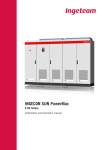
Download INGECON SUN Smart U Installation Manual
Transcript
INGECON SUN SMART U AAS2000I KI 05 Rev. _ INSTALLATION AND OPERATION MANUAL Ingeteam Energy S.A. 01/2011 Installation and Operation Manual INGECON®SUN SMART U AAS2000IKI05 The copy, distribution or use of this document or of its content requires written authorisation. Any breach thereof will be reported for damages. All rights reserved including those of patent rights or design registration. The conformity of the document content with the hardware described has been checked. However, discrepancies may exist. Liability will not be assumed for total concordance. The information contained in this document is regularly revised and it is possible that there may be changes in subsequent editions.Other functions may be available which are not covered by this document. This document may be changed. Page 2 AAS2000IKI05 Rev. _ Date: February 2011 Installation and Operation Manual INGECON®SUN SMART U AAS2000IKI05 About This Manual Purpose The purpose of this manual is to describe the Ingecon Sun SMART 15U 208, 15U 480, 25U 208 and 25U 480 and to provide the information required for its correct operation, from reception to start-up, in addition to the preventive maintenance during operation. Scope This manual provides safety guidelines, equipment information and requirements and procedures for installation and operation. Audience All installator who plans to use our equipment in a PV installation according to the requirements of the “National Electrical Code. ANSI/NFPA70” and any other local codes or laws. The installer itself has to meet all local and state code requirements. Scheme Please read this manual carefully and follow the installation instructions precisely. Symbol Identifications in this Manual The following symbols are used in this manual: WARNING Warnings advise about situations that could cause personal injury or death. CAUTION Cautions advise from situations that could cause damage to the unit or it environment. AAS2000IKI05 Rev. _ Date: February 2011 Page 3 Installation and Operation Manual INGECON®SUN SMART U AAS2000IKI05 IMPORTANT SAFETY INSTRUCTIONS SAVE THIS INSTRUCTIONS - DO NOT DISCARD This manual contains important instructions for Models Ingecon Sun 15U 208, Ingecon Sun 15U 480, Ingecon Sun 25U 208 and Ingecon Sun 25U 480 that shall be followed during installation and maintenance of the (blank space is to indicate inverter or charge controller as appropriate). WARNING The operations detailed below should only be carried out by suitably qualified personnel, trained to work with electrical equipment, familiar with this present manual and the electrical drawings associated with the control panel (hereinafter referred to as qualified personnel). You are reminded that it is compuslory to comply with applicable legislation in terms of security for electrical work. There is an electrical discharge hazard. It is essential to read the manual before operating the equipment! WARNING The opening of the various compartment enclosures in no way implies that no voltage is present inside. Access is therefore restricted to qualified personnel following the safety conditions set out in this document. WARNING The set of conditions detailed below should be considered to be the minimum requirements. It is always preferable to disconnect from the mains and check that no voltage is present. Faults in the installation could produce undesirable voltage returns. There is an electrical discharge hazard. WARNING In addition to the safety measures indicated in this manual, it is also necessary to observe the general measures applicable to this field (specific to the installation, country, etc) WARNING Compulsory to verify that no voltage is present: Use CAT III - 600 V measuring equipment. Page 4 AAS2000IKI05 Rev. _ Date: February 2011 Installation and Operation Manual INGECON®SUN SMART U AAS2000IKI05 Work always without voltage. To consider an installation “without voltage”, at least the following five steps have to have been executed: WARNING 1ª) Disconnect both DC and AC connections 2ª) Prevent any other feed. 3ª) Verify that the installation is “without voltage”. 4ª) Short-circuit AC connection and DC connection and connect it to Earth on the side “without voltage”. 5ª) Guard the installation from electric active elements phisically close, and establish security signals to limit the work zone and protect from any danger present in that zone. Potential Risks for people Here we resume the main hazards that an incorrect use of the inverter can cause on people. Inside the manual they are better explained. DANGER: Electric Shock The inverter can be charged even after being disconnected from Grid and PV Array for 5 minutes. Be sure that the 5 steps needed to work without voltage have been correctly made. DANGER: Explosion There is a very low risk of explosion in case of a major malfunction. Enclosure will protect persons and goods from explosions, but only if it is correctly closed. DANGER: Crush Follow always the instructions for moving the equipment and placing it. The high weight of this equipment can cause severe damage or death if it is not manipulated correctly. DANGER: Injures caused by Moving parts Don’t touch or manipulate fans when inverter is working.. DANGER: High Temperature Radiators and some parts inside the enclosure reach high temperatures that can be a burn hazard for people. Respect advisory marks and instructions. AAS2000IKI05 Rev. _ Date: February 2011 Page 5 Installation and Operation Manual INGECON®SUN SMART U AAS2000IKI05 Potential Risks for the Equipment Here we resume the main hazards that an incorrect use of the inverter can cause on itself. Inside the manual they are better explained. WARNING: Ventilation The inverter needs a flow of quality air to work in all the situations of its working conditions WARNING: Connections After an authorized manipulation, make sure that the inverter is completely fit to start to work until connecting. WARNING: Electronics Damage Avoid touching or electrostatically charging electronics. More sensitive components can be damaged or destroyed. WARNING: Operating Don’t connect or disconnect any terminal while the inverter is working. Disconnect and check that the equipment is without voltage first. Service personnel WARNING These servicing instructions are for use by qualified personnel only. To reduce the risk of electric shock, do not perform any servicing other than specified in the operating instructions unless you are qualified to do so. INGETEAM ENERGY S.A. don’t asume any responsability derived from not observance of this statement Personal Safety Equipment (PSE) The minimal required Safety Equipment will be: CAUTION - Safety glasses against mechanical risk damage. - Safety glasses homologued for electrical risk. - Safety footwear - Helmet - CAT III - 600 V measuring equipment. Page 6 AAS2000IKI05 Rev. _ Date: February 2011 Installation and Operation Manual INGECON®SUN SMART U AAS2000IKI05 Wiring requirements The correct wiring of the equipment to any PV installation will be done respecting the mandatory minimum section types of wire. We provide the minimum size standarized types of wire. Wider wires can be used whenever the wires would be compatible with the terminals, would have enough space to go through the conduit. AC Terminals Ingecon Sun 15U 208. Use 194ºF (90ºC) wire, either 8/AWG copper or 6/AWG aluminium: - Copper wires: - Aluminium wires: Minimun 8/AWG 0.012 in² (8.35 mm²) Minimun 6/AWG 0.02 in² (13.3 mm²) The wiring have to comply with the provisions of the National Electrical Code ANSI/NEPA70, Canadian Electrical Code CEC and other Local or State Codes. AC Terminals Ingecon Sun 15U 480. Use 12/AWG 194ºF (90ºC) wire: - Copper wires: Minimun 12/AWG 0.012in² (8.35 mm²) - Aluminium wires: Minimun 12/AWG 0.02in² (13.3 mm²) The wiring have to comply with the provisions of the National Electrical Code ANSI/NEPA70, Canadian Electrical Code CEC and other Local or State Codes. DC Terminals Ingecon Sun 15U 208 and Ingecon Sun 15U 480.Use 194ºF (90ºC) wire, either 8/AWG copper or 6/AWG aluminium: - Copper wires: Minimun 8/AWG 0.012in² (8.35 mm²) - Aluminium wires: Minimun 6/AWG 0.02in² (13.3 mm²) The wiring have to comply with the provisions of the National Electrical Code ANSI/NEPA70, Canadian Electrical Code CEC and other Local or State Codes. DC Terminals Ingecon Sun 15U 208 and Ingecon Sun 15U 480 with multi input. Use 194ºF (90ºC) wire, either 10/AWG copper or 10/AWG aluminium: - Copper wires: Minimun 11/AWG 0.006in² (4.14 mm²) - Aluminium wires: Minimun 11/AWG 0.006in² (4.14 mm²) Multi input connectors admit a maximun current of A. The wiring have to comply with the provisions of the National Electrical Code ANSI/NEPA70, Canadian Electrical Code CEC and other Local or State Codes. AC Terminals Ingecon Sun 25U 208. Use 194ºF (90ºC) wire, either 6/AWG copper or 4/AWG aluminium: - Copper wires: Minimun 6 AWG 0.02in² (13.3 mm²) - Aluminium wires: Minimun 4/AWG 0.032in² (21.2 mm²) The wiring have to comply with the provisions of the National Electrical Code ANSI/NEPA70, Canadian Electrical Code CEC and other Local or State Codes. AAS2000IKI05 Rev. _ Date: February 2011 Page 7 Installation and Operation Manual INGECON®SUN SMART U AAS2000IKI05 AC Terminals Ingecon Sun 25U 480. Use 194ºF (90ºC) wire, either 10/AWG copper or 8/AWG aluminium: - Copper wires: Minimun 10/AWG 0.008in² - Aluminium wires: Minimun 8/AWG 0.012in² The wiring have to comply with the provisions of the National Electrical Code ANSI/NEPA70, Canadian Electrical Code CEC and other Local or State Codes. DC Terminals Ingecon Sun 25U 208 and Ingecon Sun 25U 480.Use 194ºF (90ºC) wire, either 4/AWG copper or 2/AWG aluminium: - Copper wires: Minimun 4/AWG 0.032in² - Aluminium wires: Minimun 2/AWG 0.052in² The wiring have to comply with the provisions of the National Electrical Code ANSI/NEPA70, Canadian Electrical Code CEC and other Local or State Codes. Tightening torques AC Terminals Ingecon Sun 15U 208: - Copper wires 8/AWG: 8.5 pound-in (9 Nm). - Aluminium wires 6/AWG: 12.4 pound-in (18.6 Nm). AC Terminals Ingecon Sun 15U 480: - Copper wires 12/AWG: 8.5 pound-in (9 Nm). - Aluminium wires 12/AWG: 8.5 pound-in (9 Nm). DC Terminals Ingecon Sun 15U 208 and Ingecon Sun 15U 480: - Copper wires 8/AWG: 8.5 pound-in (9 Nm). - Aluminium wires 6/AWG: 12.4 pound-in (18.6 Nm). AC Terminals Ingecon Sun 25U 208: - Copper wires 6 AWG: 12.4 pound-in (18.6 Nm). - Aluminium wires 4/AWG: 12.4 pound-in (18.6 Nm). AC Terminals Ingecon Sun 25U 480: - Copper wires 10/AWG: 8.5 pound-in (9 Nm). - Aluminium wires 8/AWG: 8.5 pound-in (9 Nm). DC Terminals Ingecon Sun 25U 208 and Ingecon Sun 25U 480: Page 8 - Copper wires 4/AWG: 12.4 pound-in (18.6 Nm). - Aluminium wires 2/AWG: 16.9 pound-in (31.3 Nm). AAS2000IKI05 Rev. _ Date: February 2011 Installation and Operation Manual INGECON®SUN SMART U AAS2000IKI05 Spare parts During the life of the equipments, they may need some maintenance, that could involve replacing some parts. Here is shown the list of the parts that has to be provided only by Ingeteam Energy S.A.: Ingecon Sun 15U 208 AAS2000IKI05 Rev. _ Date: February 2011 Reference units Description BF3, BF4 2 DC Fuseholders F4 (F3) 1 Fuse to connect from one of DC poles to Earth. Q1, Q2 2 6-10A Contactor IQ1, IQ2, IQ3 2 Signaller for GV2-P MT Circuit Breaker Q3 1 0,1-0,16A MT Breaker QAC 1 TMAX T2 AC 3P 50A 50kA MT Circuit Breaker QAC.AUX 1 TMAX T2 auxiliary MT Circuit Breaker QAC.B 1 TMAX T2 terminal accessories QAC.MANDO 1 Rotary handle TMAX R1, R2, R3 3 0.1R 90W silicon coverered resistor R4 1 220 2w 5% RC resistor, RC fans RVAC 1 40 kA 130V 4P AC voltage surge arrester with signal RVDC 1 DC 600V 2+1 DC voltage surge arrester monitored VENT1, VEN2 2 119x119x38mm 230Vac fan AAS0091 1 Display hardware, keyboard and LED with CAN. AAS0109 1 Harmonic filter hardware 40uF string AAS7137 1 Ingecon Sun 15U 208 Electronics Block AQG0081 1 130/230 75VA auxiliary transformer C1 1 300Vac 220nF polypropilene capacitor CCC 1 EMI AC 50A filter F1 (F2) 1 700V 90A 100kA DC fuse fast acting KA 1 75A UL contactor device BF1 (BF2) 1 Fuse holders QDC 1 DC breaker 4 poles 100A QDC.PR 1 Coupling stick QDC. MANDO 1 Rotary handle for DC breaker QDC.E 1 Trim for DC breaker Page 9 Installation and Operation Manual INGECON®SUN SMART U AAS2000IKI05 Ingecon Sun 15U 480 Page 10 Reference units Description BF3, BF4 2 DC Fuseholders F4 (F3) 1 Fuse to connect from one of DC poles to Earth. Q1, Q2 2 6-10A Contactor IQ1, IQ2, IQ3 2 Signaller for GV2-P MT Circuit Breaker Q3 1 0,1-0,16A MT Breaker QAC 1 QAC.AUX 1 TMAX T2 auxiliary MT Circuit Breaker QAC.B 1 TMAX T2 terminal accessories QAC.MANDO 1 Rotary handle TMAX R1, R2, R3 3 0.1R 90W silicon coverered resistor R4 1 220 2w 5% RC resistor, RC fans RVAC 1 RVDC 1 DC 600V 2+1 DC voltage surge arrester monitored VENT1, VEN2 2 119x119x38mm 230Vac fan AAS0091 1 Display hardware, keyboard and LED with CAN. AAS0165 1 Harmonic filter hardware 40uF string AAS7136 1 Ingecon Sun 15U 480 Electronics Block AQG 1 auxiliary transformer C1 1 300Vac 220nF polypropilene capacitor CCC 1 F1 (F2) 1 700V 150A 100kA DC fuse fast acting BF1 (BF2) 1 Fuse holders KA 1 QDC 1 DC breaker 4 poles 200A QDC.PR 1 Coupling stick QDC. MANDO 1 Rotary handle for DC breaker QDC.E 1 Trim for DC breaker AAS2000IKI05 Rev. _ Date: February 2011 Installation and Operation Manual INGECON®SUN SMART U AAS2000IKI05 Ingecon Sun 25U 208 AAS2000IKI05 Rev. _ Date: February 2011 Reference units Description BF3, BF4 2 DC Fuseholders F4 (F3) 1 Fuse to connect from one of DC poles to Earth. Q1, Q2 2 6-10A Contactor IQ1, IQ2, IQ3 2 Signaller for GV2-P MT Circuit Breaker Q3 1 0,1-0,16A MT Breaker QAC 1 TMAX T2 AC 3P 90A 50kA MT Circuit Breaker QAC.AUX 1 TMAX T2 auxiliary MT Circuit Breaker QAC.B 1 TMAX T2 terminal accessories QAC.MANDO 1 Rotary handle TMAX R1, R2, R3 3 0.1R 90W silicon coverered resistor R4 1 220 2w 5% RC resistor, RC fans RVAC 1 40 kA 130V 4P AC voltage surge arrester with signal RVDC 1 DC 600V 2+1 DC voltage surge arrester monitored VENT1, VEN2 2 119x119x38mm 230Vac fan AAS0091 1 Display hardware, keyboard and LED with CAN. AAS0165 1 Harmonic filter hardware 40uF string AAS7135 1 Ingecon Sun 25U 480 Electronics Block AQG0081 1 120/230 75VA auxiliary transformer C1 1 300Vac 220nF polypropilene capacitor CCC 1 EMI AC 80A filter F1 (F2) 1 700V 150A 100kA DC fuse fast acting KA 1 75A UL contactor device BF1 (BF2) 1 Fuse holders QDC 1 DC breaker 4 poles 200A QDC.PR 1 Coupling stick QDC. MANDO 1 Rotary handle for DC breaker QDC.E 1 Trim for DC breaker Page 11 Installation and Operation Manual INGECON®SUN SMART U AAS2000IKI05 Ingecon Sun 25U 480 Page 12 Reference units Description BF3, BF4 2 DC Fuseholders F4 (F3) 1 Fuse to connect from one of DC poles to Earth. Q1, Q2 2 6-10A Contactor IQ1, IQ2, IQ3 2 Signaller for GV2-P MT Circuit Breaker Q3 1 0,1-0,16A MT Breaker QAC 1 TMAX T2 AC 3P 40A 50kA MT Circuit Breaker QAC.AUX 1 TMAX T2 auxiliary MT Circuit Breaker QAC.B 1 TMAX T2 terminal accessories QAC.MANDO 1 Rotary handle TMAX R1, R2, R3 3 0.1R 90W silicon coverered resistor R4 1 220 2w 5% RC resistor, RC fans RVAC 1 40 kA 385V 4P AC voltage surge arrester with signal RVDC 1 DC 600V 2+1 DC voltage surge arrester monitored VENT1, VEN2 2 119x119x38mm 230Vac fan AAS0091 1 Display hardware, keyboard and LED with CAN. AAS0165 1 Harmonic filter hardware 40uF string AAS7135 1 Ingecon Sun 25U 480 Electronics Block AQG0080 1 277/230 75VA auxiliary transformer C1 1 300Vac 220nF polypropilene capacitor CCC 1 EMI AC 35A filter F1 (F2) 1 700V 150A 100kA DC fuse fast acting BF1 (BF2) 1 Fuse holders KA 1 40A UL contactor device QDC 1 DC breaker 4 poles 200A QDC.PR 1 Coupling stick QDC. MANDO 1 Rotary handle for DC breaker QDC.E 1 Trim for DC breaker AAS2000IKI05 Rev. _ Date: February 2011 Installation and Operation Manual INGECON®SUN SMART U AAS2000IKI05 Inverter Marking The identifying marks of the inverter are: Phase 1 terminal and wire connection Phase 2 terminal and wire connection Phase 3 terminal and wire connection Neutral terminal and wire connection DC input. Grounding. AAS2000IKI05 Rev. _ Date: February 2011 Page 13 Installation and Operation Manual INGECON®SUN SMART U AAS2000IKI05 Related documentation CATALOGUES ® Ingecon Sun Commercial Catalogue PC00ISA01_A MANUALS ® Ingecon Sun LITE U Installation & Operator Manual AAY2000IKI02 ® ® Ingecon Sun SMART U Installation & Operator Manual AAS2000IKI05 ® Ingecon Sun POWER U Installation & Operator Manual Ingecon Sun Manager User’s Manual AAS2000IKI04 AAX2005IKL01 Communication Accessories Installation Manual AAX2002IKI01 Page 14 AAS2000IKI05 Rev. _ Date: February 2011 Installation and Operation Manual INGECON®SUN SMART U AAS2000IKI05 0 Index 1. Overview 17 17 17 17 17 18 18 21 2. Description of the system 22 22 22 22 22 23 23 24 24 24 25 25 25 27 3. Operating, storage and transport conditions 29 29 29 30 31 32 32 33 4. Safety instructions 34 34 34 35 36 37 37 38 38 38 38 39 1.1 Introduction 1.2 Description of the equipments 1.2.1 Models 1.2.2 Options 1.3 Technical data 1.4 Ratings 1.5 Compliance with Standards 2.1 Location 2.1.1 Site 2.1.2 NEMA rating 2.1.3 Ambient temperature 2.1.4 Atmospheric conditions 2.1.5 Ventilation 2.1.6 Contamination rating 2.1.7 Noise contamination 2.1.8 Anchorage 2.2 Ground Requirements 2.3 System neutral requirements 2.4 Electrical Diagrams 2.5 Conduit Entry 3.1 Safety notice 3.2 Equipment reception 3.3 Handling and unpacking 3.4 Equipment transport 3.5 Storage 3.6 Conservation 3.7 Waste disposal 4.1 Contents 4.2 Symbols 4.3 General safety conditions 4.4 General observations 4.4.1 Hazards present and general preventive measures 4.4.2 Hazards and additional measures in manipulation work 4.5 Type of tasks to be performed 4.5.1 Inspection tasks 4.5.2 Operational tasks 4.5.3 Manipulation tasks 4.5.4 Personal Protection Equipment (PPE) AAS2000IKI05 Rev. _ Date: February 2011 Page 15 Installation and Operation Manual INGECON®SUN SMART U AAS2000IKI05 5. Installation 40 40 40 41 42 42 42 43 44 45 46 6. Commissioning 49 49 49 50 50 50 51 7. Preventive maintenance 52 52 8. Troubleshooting 55 55 55 55 55 55 56 56 56 56 56 57 58 9. Operating the display 59 59 60 61 61 64 65 66 5.1 General installation requirements 5.2 Anchoring the equipment to the floor 5.3 Opening the equipment 5.4 Order of connection 5.5 GSM/GPRS - Modem communication connection 5.6 RS485 line - Communication connection 5.7 Ethernet - Communication connection 5.8 Grounding 5.9 Connection to the Power Grid 5.10 Connection to the PV array 6.1 Equipment inspection 6.1.1 Inspection 6.1.2 Equipment seal 6.2 Power-up 6.2.1 Start-up 6.2.2 Checking and measurement 7.1 Maintenance tasks 8.1 LED indicators 8.1.1 Green LED 8.1.1.1 Slow flashing 8.1.1.2 Fast flashing 8.1.1.2 Light constantly on 8.1.2 Orange LED 8.1.2.1 Fast flashing 8.1.3 Red LED 8.1.3.1 Constantly on 8.1.4 Three LED flashing simultaneously 8.2 List of alarms and stop reasons 8.3 Inverter alarms triggered by protections 9.1 Keypad and LEDs 9.2 Display 9.3 Main menu 9.4 Monitoring 9.5 Stop reasons 9.6 Settings 9.7 Inverter data Page 16 AAS2000IKI05 Rev. _ Date: February 2011 Installation and Operation Manual INGECON®SUN SMART U AAS2000IKI05 1 Overview 1.1 Introduction The purpose of this manual is to describe the INGECON SUN SMART U equipments and to provide adequate information for its correct location, installation, commissioning, maintenance and operation. 1.2 Description of the equipments An inverter is a circuit used to convert direct current into alternating current. The INGECON SUN SMART U therefore serves to convert the direct current generated by the PV solar panels into alternating current to be delivered to the electricity grid. 00000 Paneles SolaresPanels Photovoltaic Fotovoltaicos Inversor Fotovoltaico Photovoltaic Inverter ContadorCounter - Protections Protecciones Red de Distribución Electrical Distribution Grid Eléctrica 1.2.1 Models The models included in the INGECON SUN SMART U range are as follows: 1.2.2 Options AAS2000IKI05 Rev. _ Date: February 2011 - INGECON SUN 15 U 208V - INGECON SUN 15 U 480V - INGECON SUN 25 U 208V - INGECON SUN 25 U 480V The models from the INGECON SUN 15 U 208V and INGECON SUN 15 U 480V can include DC multi-input or DC copper plate. Page 17 Installation and Operation Manual INGECON®SUN SMART U AAS2000IKI05 1.3 Technical data Product feautures Options Wide input voltage range (300 – 600 Vdc). Advanced system for maximum power point tracking (MPPT). Easy to install, with no need for additional components. DC, AC and communication quick plug-in. Built-in electrical protection. Galvanic AC isolation transformer. Steel enclosure NEMA 3R. Manual grid disconnect feature. Status LEDs, LCD screen and keyboard for data monitoring at the front of the unit. Protection against reverse polarity, voltage surges, short circuits, insulation defects. Anti-islanding monitoring system with automatic disconnection. Internal data logger offering 3 month store capacity. Inter-inverter communication via an RS-485, fiber optics, wireless or Ethernet card. Modem for GSM/GPRS remote communications. Internet data display. Remote access and fault diagnostics. Analog input electronics for the measurement of weather variables. Software Ingecon®Sun Manager for the parameter display, data recording, etc. Contact relay to act in case of DC earth fault. 1.4 Ratings DC Input Ratings Ingecon®Sun 15U 208 15U 480 Range of input operating voltage Page 18 600 V dc 52.6 A Maximum input short circuit current 100 A Maximum input source backfeed 30 A current to input source Maximum current to input source (A) 25U 480 300 - 600 V dc Maximun input voltage Maximum input current 25U 208 52.6 A 87.7 A 100 A 200 A 70 A 50 A 87.7 A 200 A 100 A 0 AAS2000IKI05 Rev. _ Date: February 2011 Installation and Operation Manual INGECON®SUN SMART U AAS2000IKI05 Ac Output Ingecon®Sun 15U 208 15U 480 Output power factor rating Operating voltage range (ac) (L-L)1 183 - 229 V ac 422.5 - 528 V ac current (ac) and duration Maximum output 3F + N 480 V 41.6 18 69.4A 30.1 A 15 kVA (15 kW) 15 kVA (15 kW) 25 kVA (25 kW) 25 kVA (25 kW) 159A @ 9.6ms 74A @ 9ms 206A @ 11.2ms 266A @ 8.8ms 70 A 30 A 100 A 50 A 480 V +/-1% Frequency: +/-0.1 Hz Time 0.060 secs Normal operation temperature range Maximum full power 208 V 60 Hz overcurrent protection Utility interconnection voltage and frequency trip limits and trip time accuracy. Voltage: Trip limit and trip time accuracy 422.5 - 528 V ac 208 V Normal output frequency Maximum output fault 183 - 229 V ac 59.3 - 60.5 Hz Number of phases Maximum continuous output current ac per line Power 25U 480 >0.99 Operating frequency range Nominal output voltage (ac) 25U 208 -15 - +55°C +55°C +45°C operating ambient Enclosure Rating Type AAS2000IKI05 Rev. _ Date: February 2011 3R Page 19 Installation and Operation Manual INGECON®SUN SMART U AAS2000IKI05 Notes: 1. Utility Interconnection Voltage and Frequency Trip Limits and Trip Times: Condition Simulated utility source Maximum time (sec) at 60 Hz before cessation of current to the simulated utility Voltage (V) Frequency (Hz) A < 0.50 Vnor Rated 0.16 B 0.50 Vnor ≤ V < 0.88 Vnor (Adjustable Set Points) Rated 0.16 to 2.667 (Adjustable Set Points) C 1.10 Vnor < V < 1.11 Vnor Rated (Adjustable Set Points) 0.16 to 2 (Adjustable Set Points) D 1.20 Vnor ≤ V Rated 0.16 E Rated f > 60.5 0.16 F Rated f < (59.8 – 57.0) (Adjustable Set Points) 0.16 to 300 G Rated f < 57 0.16 2. Utility interactive evaluations were conducted with the following firmware: 15 kW. DSP Firmware versions (208V): AAS1038 0x1DF3 MICRO Firmware versions (208V): NA DSP Firmware versions (480V): AAS1037 0xB734 MICRO Firmware versions (480V): NA Check sums: Check sums: NA Check sums: Check sums: NA 25 kW. DSP Firmware versions (208V): AAS1036 0x59OA MICRO Firmware versions (208V): NA Check sums: NA DSP Firmware versions (480V): AAS1035 MICRO Firmware versions (480V): NA Check sums: 0x2981 Check sums: NA Check sums: 3. Surge Testing for Combination Wave (1.2/50us) was done at 6 kV/3 kA, 2 ohms effective impedance, and Ringwave (0.5us-100kHz) was done at 6 kV/0.5 kA, 12 ohms effective impedance. Tests were performed using both polarities, for common mode and differential mode coupling, 20 pulses each test. After surge testing the unit was operational with control functionally verified by frequency and voltage disconnect tests. Page 20 AAS2000IKI05 Rev. _ Date: February 2011 Installation and Operation Manual INGECON®SUN SMART U AAS2000IKI05 1.5 Compliance with Standards CAN/CSA-C22.2 No. 0-M91 - General Requirements - Canadian Electrical Code Part II 0.4-04 - Bonding of Electrical Equipment 107.1-01 - General Use Power Supplies UL Std No. 1741 - First Edition - Inverters, Converters, Controllers and Interconnection System Equipment for Use With Distributed Energy Resources (Including Revisions through and including November 7, 2005) AAS2000IKI05 Rev. _ Date: February 2011 Page 21 Installation and Operation Manual INGECON®SUN SMART U AAS2000IKI05 2 Description of the system 2.1 Location 2.1.1 Site The INGECON-SUN SMART U units need to be located at a site offering specific characteristics. This section provides guidelines for selecting and correctly adapting the equipment to a suitable site Locate the units in a place which is easily accessible for installation and maintenance work, with sufficient room to operate the keyboard and to read the front LED indicators. It is forbidden to leave objects on the equipment. Caution: Air outlets and part of the nearby cabinet can reach temperatures of 85 ºC. Do not leave high temperature sensitive material in the vicinity. Avoid corrosive environments. 2.1.2 NEMA rating The Ingecon® Sun Three-phase inverters has NEMA Type 3R Degree of Protection. The inverter protection rating against external agents allows it to be installed outdoors. Dust free air must be provided in the enviroment of the equipment. Air quality will be asured. 2.1.3 Ambient temperature The INGECON-SUN SMART U, are designed to operate between –4ºF (-20ºC) and +131ºF (+55ºC). Maximum full power operating ambient temperature is +113ºF (+45ºC). Page 22 AAS2000IKI05 Rev. _ Date: February 2011 Installation and Operation Manual INGECON®SUN SMART U AAS2000IKI05 2.1.4 Atmospheric conditions The surrounding air should be clean and the relative humidity should not exceed 50%, at more than +104ºF (+40ºC). Higher percentages of relative humidity, up to 95%, are tolerable at temperatures below +86ºF (+30ºC). Account should be taken of the fact that, occasionally, moderate condensation may occur as a result of temperature variations. For this reason, in addition to the inverter’s own protection system, the equipment should also be monitored when operating at sites which may not come within the atmospheric conditions described above. When condensation is present, never power up the equipment. 2.1.5 Ventilation There must be a 8 in (20.3 cm) clearance at the sides and front of the equipment, to promote the free circulation of air through the grids. Facilitate the circulation of incoming air through the vents and through the lower pit, if present, and also the outgoing air through the upper vents. STOP It is forbidden to leave objects on the equipment. The fans move an air flow of 674m3/h that has to be available in the environment of the equipment to make sure a correct cooling. AAS2000IKI05 Rev. _ Date: February 2011 Page 23 Installation and Operation Manual INGECON®SUN SMART U AAS2000IKI05 2.1.6 Contamination rating The equipment has been designed for a grade 3 contamination rating. Appropriate measures should be taken to ensure that the inverter air supply is dust free and of sufficient quality. 2.1.7 Noise contamination When operating, the inverters give off a slight buzzing sound. Do not locate the inverters in an occupied room, or on lightweight supports which could amplify this noise. The mounting surface must be firm and adequate for the weight of the equipment. 2.1.8 Anchorage INGECON-SUN SMART U can be equipped with an optional docking system. The system consists of 4 plates bolted to the four corners of the inverter’s base to secure the inverter to the concrete pad. The system requires following next screwing prescriptions: - Minimun distance between the center of thedrill on the concrete slab to its borders of 3 in (76 mm). - Diameter of the drill on the concrete slab to its borders of 0.31 in (8 mm). - Minimun depth of thedrill on the concrete slab of 3 in (76 mm). - Minimun thickness of the concrete slab of 4 in (102 mm). - Torque of 14.75 lb-ft (20 Nm). - Minimun depth of the screw of 2 in (51 mm). 2 in. 3 in. 3 in. concret 4 in. Page 24 AAS2000IKI05 Rev. _ Date: February 2011 Installation and Operation Manual INGECON®SUN SMART U AAS2000IKI05 2.2 Ground Requirements The Ingecon® Sun equipments have to be integrated in a permanently grounded electrical system conforming the provisions of the National Electrical Code ANSI / NFPA 70 and any other statal or local code requirements. 2.3 System Neutral Requirements The INGECON SUN 15 U 208V and INGECON SUN 15 U 480V are designed to be installed to four-wire systems (3 phases+neutral) with 208 V line-to-line. The INGECON SUN 25 U 208V and INGECON SUN 25 U 480V are designed to be installed to four-wire systems (3 phases+neutral) with 480 V line-to-line. It’s mandatory to connect the neutral wire. 2.4 Electrical Diagrams INGECON SUN 15 U 208V PV Input + - Only the hot pole have the fuse installed Fused disconnect switch Inverter Transformer Breaker 3 X 208 Vac 60 Hz 3 Neutral AC voltage surge arresters DC voltage surge arresters One of the two fuses has to be installed Contactor N MOV’s Enclosure and other metal parts, always Grounded. INGECON SUN 15 U 480V PV Input + - One of the two fuses has to be installed AAS2000IKI05 Rev. _ Date: February 2011 Only the hot pole have the fuse installed Fused disconnect switch Inverter 3 DC voltage surge arresters Transformer Contactor Breaker 3 X 480 Vac 60 Hz Fuses AC voltage surge arresters Neutral N MOV’s Enclosure and other metal parts, always Grounded. Page 25 Installation and Operation Manual INGECON®SUN SMART U AAS2000IKI05 INGECON SUN 15 U 208V with multi-inputs (optional) + + + + + + - Inverter + - Fused disconnect switch Transformer 3 Breaker 3 X 208 Vac 60 Hz Fuses Neutral AC voltage surge arresters DC voltage surge arresters PV Input Contactor N MOV’s Enclosure and other metal parts, always Grounded. One of the two fuses has to be installed INGECON SUN 15 U 480V with multi-inputs (optional) + + + + + + - The hot pole have the fuse installed Inverter + - Fused disconnect switch Transformer 3 Breaker 3 X 480 Vac 60 Hz Fuses Neutral AC voltage surge arresters DC voltage surge arresters PV Input Contactor N MOV’s Enclosure and other metal parts, always Grounded. One of the two fuses has to be installed INGECON SUN 25 U 208V Only the hot pole have the fuse installed PV Input + - One of the two fuses has to be installed Page 26 Inverter Fused disconnect switch 3 DC voltage surge arresters Transformer Contactor Breaker 3 X 208 Vac 60 Hz Fuses AC voltage surge arresters Neutral N MOV’s Enclosure and other metal parts, always Grounded. AAS2000IKI05 Rev. _ Date: February 2011 Installation and Operation Manual INGECON®SUN SMART U AAS2000IKI05 INGECON SUN 25 U 480V PV Input + - Only the hot pole have the fuse installed Transformer 3 Fused disconnect switch Contactor Breaker 3 X 480 Vac 60 Hz Fuses AC voltage surge arresters DC voltage surge arresters One of the two fuses has to be installed 2.5 Inverter Neutral N MOV’s Enclosure and other metal parts, always Grounded. Conduit Entry The INGECON SUN SMART U wires musst go through the enclusure by conduits. On the base of the enclosure there are several knockouts designed to be opened and lodge a conduit. Don’t open any knockout that won’t be used. It could affect to NEMA degree. Knockouts have been designed to be used in wiring as picture shows. For a different use first ask INGETEAM. view of the base of the enclosure AC grounding DC grounding DC input DC input communication input AC grounding AC input communication input AAS2000IKI05 Rev. _ Date: February 2011 Page 27 Installation and Operation Manual INGECON®SUN SMART U AAS2000IKI05 In following tables are shown the conduits needed for each hole. The holes are the same for all INGECON SUN SMART U Conduit DC grounding hole 1 /4 Hole 1.69 in (43 mm) DC input holes 11/2 2 in (51 mm) /2 0.86 in (22 mm) 11/2 2 in (51 mm) /2 0.86 in (22 mm) 1 AC grounding holes 1 AC output hole communication wiring holes Number of wires DC DC Multi DC Multi grounding AC 208 V Grounding AC 208 Grounding DC Page 28 1 Section Required size Number of wires admitted 3 29 13 41(11/2) 1 1 AWG 1 AWG 10 AWG 10 1 1 AWG 3 AWG 4 41(11/2) 16(1 /2) 5 1 1 AWG 4 16(11/2) 1 53(2) 35(11/4) 1 AAS2000IKI05 Rev. _ Date: February 2011 Installation and Operation Manual INGECON®SUN SMART U AAS2000IKI05 3 Operating, Storage and Transport Conditions 3.1 Safety notice Failure to comply with the instructions provided in this section could cause damage to the equipment. Ingeteam Energy S.A. assumes no liability whatsoever for any damage derived from non-compliance with these instructions. 3.2 Equipment reception WARNING: Equipment is heavy. Packed equipment weights approximately 255 kgrs or 325 kgrs. 15 kW or 25 kW models. Read carefully this instructions until moving the pack. On reception, please check the terms indicated in the Delivery Note, sign the box: FIRMA RECEPTOR MERCANCIA, to indicate that you have received the merchandise, and return the signed copy to the sender’s address. CAUTION. Do not storage in environments up to 55ºC or less than -20ºC of temperature. Avoid humidity. Palets with following characteristics will be received: MODEL PALET TYPE WEIGHT (pounds) HEIGHT/WIDTH/LENGTH (in) 15U 208 Wooden: Bubble wrap 771 55 / 35 / 25 771 55 / 35 / 25 25U 208 771 55 / 35 / 25 25U 480 771 55 / 35 / 25 15U 480 Identifying the equipment The serial number clearly identifies the inverter. All communications with Ingeteam Energy S.A. should indicate this number: Serial Number AAS2000IKI05 Rev. _ Date: February 2011 Page 29 Installation and Operation Manual INGECON®SUN SMART U AAS2000IKI05 Damage during transport Should the equipment sustain damage during transport: 1) Do not install it 2) Notify your distributor immediately of this situation, within 5 days as of the reception date. Should it be necessary to return the equipment to the manufacturer, the original packaging should be used. 3.3 Handling and unpacking It is exceedingly important to correctly handle the equipment at all times in order to ensure that: • The packaging remains intact and the equipment is maintained in optimum condition right from shipment until unpacking. • The equipment is not knocked and / or dropped, which could affect the mechanical characteristics, such as poor door closure, loss of IP rating etc. • Every effort is made to prevent vibrations which could lead to subsequent malfunctioning. Should any anomaly be observed, please contact INGETEAM immediately. Disposal of the packaging All the packaging can be given to an authorised non hazardous waste manager. If available, each part of the packaging should be disposed of as follows: Plastic (polystyrene, bag and bubble wrap): Plastics and containers municipal container. Cardboard: Paper and cardboard municipal container. Page 30 AAS2000IKI05 Rev. _ Date: February 2011 Installation and Operation Manual INGECON®SUN SMART U AAS2000IKI05 3.4 Equipment transport Correct transport and storage are the first steps required for correct equipment use and operation. Considering the indications given in section 3.3 and as a preventive measure INGETEAM would recommend working with hauliers specialising in the transport of special and / or fragile equipment. During transport and storage the equipment should be protected from mechanical impacts, vibrations, water projections (rain) and any other product or situation which could damage or alter its performance. Failure to comply with these instructions could void the product warranty, for which INGETEAM is not liable. When moving this equipment, bear in mind that the equipment centre of gravity is at 1/3 the height of its plan view projection. Transport by truck To transport the INGECON-SUN SMART U on a truck, it is essential to maintain the equipment upright and correctly anchored, considering its weight and dimensions, in order to avoid it tipping over or being damaged by impact. Moving the equipment with a fork lift truck At least the following points should be observed: 1) Ensure that the packaged equipment is centred over the forks. 2) Try to ensure that the equipment is placed as close as possible to the connection between the fork and the carriage. 3) Ensure that the forks are perfectly level, to prevent the equipment from being tipped off.. 4) In any event, observe the instructions provided in the fork lift truck manual. AAS2000IKI05 Rev. _ Date: February 2011 Page 31 Installation and Operation Manual INGECON®SUN SMART U AAS2000IKI05 3.5 Storage If the equipment is not to be installed immediately after reception, then the following points should be taken into account in order to avoid deterioration: • The package should be stored upright. • Keep the equipment free from dirt (dust, shavings, grease …) and out of the reach of rodents. • Avoid contact with water jets, welding sparks, etc. • Cover the equipment with a breathable, protective material in order to avoid condensation caused by ambient humidity. • The equipment stored at the manufacturing plant and that stored on the customer’s premises must be maintained with the ambient conditions indicated in section 3.2.5. • It is extremely important to protect the equipment from contact with chemicals, which could cause corrosion, and also from saline atmospheres. 3.6 Conservation In order to conserve the equipment correctly, the original packaging should not be removed until just before the equipment is due to be installed. In the event of prolonged storage, we would recommend storage in a dry place, avoiding abrupt temperature changes, as far as possible. Should the packaging be damaged /cuts, holes, etc) the equipment will not be maintained in optimum condition before installation. INGETEAM ENERGY S.A. assumes no liability if this condition is not complied with. Page 32 AAS2000IKI05 Rev. _ Date: February 2011 Installation and Operation Manual INGECON®SUN SMART U AAS2000IKI05 3.7 Waste disposal During the installation, start-up and maintenance procedures, the waste generated must be adequately treated in compliance with the countryspecific regulations. At the end of the equipment useful life, the waste must be given to an authorised manager. In this section, Ingeteam Energy S.A., in its commitment to an environmentally friendly policy, provides Authorised Managers with information on the location of the components to be decontaminated. Those equipment components which must be specifically treated are: 1. Batteries or accumulators 2. Printed circuit boards 3. Liquid crystal displays. The following photos show the location of these components. 1 2 3 2 AAS2000IKI05 Rev. _ Date: February 2011 Page 33 Installation and Operation Manual INGECON®SUN SMART U AAS2000IKI05 4 Safety instructions 4.1 Contents This section contains the safety instructions to be followed when installing, operating and accessing the equipment. Failure to comply with these “Safety Instructions•may result in physical injury or even death, or cause damage to the equipment. Before operating the equipment, please read these “safety instructions” carefully. 4.2 Symbols Safety warnings provide information on conditions that could cause serious bodily injury or death and / or damage to the equipment. Together with the warning sign, instructions are given as to how to avoid such hazards. These symbols are listed below with an explanation of their meaning. Danger. High voltage. Stay away! A warning that the high voltage present in the equipment could cause physical injury or even death and / or damage to the equipment. General warning!: regarding conditions that could result in physical injury and / or damage to the equipment. Caution hot surface!: warning about the presence of hot parts that could cause serious burns. All work-specific safety warnings and notes are included in each corresponding chapter and are also repeated and completed at the critical points in that chapter. Please read this information carefully. It has been written with your personal safety in mind, whilst ensuring the maximum service life for the equipment itself and for any devices connected to it. Page 34 AAS2000IKI05 Rev. _ Date: February 2011 Installation and Operation Manual INGECON®SUN SMART U AAS2000IKI05 4.3 General safety conditions The installation, commissioning, inspection and maintenance operations may only be performed by suitably qualified personnel, trained to work with electrical equipment (hereinafter qualified personnel). You are reminded that it is mandatory to comply with all safety regulations and standards applicable to electrical work. The opening of the various compartment enclosures in no way implies that no voltage is present inside. Access is therefore restricted to qualified personnel, observing the safety conditions established in this document. The set of conditions detailed below should be considered to be the minimum requirements. It is always advisable to disconnect from the mains. The installation could be faulty, causing undesirable voltage returns. There is an electrical discharge hazard. In addition to the safety measures indicated in this manual, any general measures that may be applicable should also be taken into account (installation-specific, country-specific, etc). According to the basic safety standards and regulations, the electrical installation must not entail fire or explosion hazards. Workers must be properly protected against the risk of accidents caused by direct or indirect contact. The electrical installation and the protective devices must take account of the voltage, all external conditioning factors and the competence of those people having access to the installation parts. According to the basic safety standards and regulations, all work equipment must be adequate for protecting exposed workers against the risk of direct or indirect contact with electricity. At any event, the electrical parts of the equipment must comply with the provisions of the corresponding specific standards and regulations. According to the basic safety standards and regulations, for voltage work, all workers performing work in the open air shall stop work in the event of storms, heavy rainfall, strong winds, snow or any other unfavourable environmental condition that hinders visibility or the handling of tools. Work on indoor installations directly connected to overhead electricity lines must be interrupted in the event of a storm. AAS2000IKI05 Rev. _ Date: February 2011 Page 35 Installation and Operation Manual INGECON®SUN SMART U AAS2000IKI05 INGETEAM assumes no liability whatsoever for damages caused by the improper use of the equipment. Any work on any of this equipment and involving a change in the original electrical layout, must fist be proposed to INGETEAM. This proposed new layout must then be studied and authorised by INGETEAM. The necessary safety measures must be in place to prevent unauthorised persons from handling the equipment and to keep them away from the vicinity of the equipment. Warning signs to indicate the presence of personnel at work: Lockout mechanisms or mechanical locking, by padlocks with keys, for circuit breakers of an appropriate type. These instructions must be easily accessible, close to the equipment and within easy reach of all users. Before installing and commissioning the equipment, please read these safety instructions and warnings carefully and all the warning signs placed on the equipment. Ensure that all warning signs are perfectly legible and that any damaged or missing signs are replaced. 4.4 General observations This section defines the preventive measures to be adopted when performing all types of work on the equipment, in order to work safely and control unavoidable hazards. Protection against direct contact is provided by the enclosure with a protection rating of NEMA 3R. The equipment has been tested to the applicable standards and regulations to ensure that it complies with the safety requirements, the insulation distance values and the leakage lines for the voltages used. The tools and / or equipment used for the equipment manipulation tasks must have double reinforced insulation (class II). Page 36 AAS2000IKI05 Rev. _ Date: February 2011 Installation and Operation Manual INGECON®SUN SMART U AAS2000IKI05 4.4.1 Hazards present and general preventive measures • Impact against stationary objects: - Inform the workers of the hazard. - Adequate lighting. - Work carefully. - Maintain sufficient distance to avoid contact with the hazard (control rod on circuit breaker door). • Blows, jabs and cuts with objects and / or tools: - Keep the cover closed when not working in the cubicle. - Adequate lighting. - Good housekeeping. - Mandatory use of a helmet, safety footwear and gloves when required. • Particle projection (fan): - It is advisable to use anti-impact glasses when accessing the fan area. • Electrical hazard: - Comply with the provisions in the PPE section and in the General Safety Conditions section. - Inform the workers of the hazard. - Comply with the provisions of applicable Federal, Statal and Local laws and rules. 4.4.2 Hazards and additional measures in manipulation work • Thermal contact: - Inform the workers of the hazard. - It is advisable to wear gloves. - Disconnect the power supply and wait 10 minutes to allow the hot parts in the equipment interior to cool down (R1, RAD1). Thermal hazard AAS2000IKI05 Rev. _ Date: February 2011 Page 37 Installation and Operation Manual INGECON®SUN SMART U AAS2000IKI05 4.5 Type of tasks to be performed Preventive maintenance tasks performed on the electric panels can involve Inspection, Operational or Manipulation tasks, depending on each particular case. It is strictly forbidden to access the enclosure through a cubicle other than the one described in this manual. Before opening any of the enclosure covers (side, rear, top) the exterior power supply to the panel must first be cut off. 4.5.1 Inspection tasks Deficinición: Implican la apertura de la envolvente para tareas de inspección visual. 4.5.2 Operational tasks Definition: Tasks involving loading software, checking and regulating the heating / ventilation systems. Voltage checks at safe measurement points. Equipment preventive maintenance tasks not including the electric panels, performed from the man - machine interface. For operational work referring to checking and changing the automatic breaker settings, it is strictly forbidden to manipulate or access any of the breaker parts (terminals, cables, protective devices) during this operation other than the specific control for checking and / or changing the breaker setting. 4.5.3 Manipulation tasks Definition: Tasks involving the assembly and / or replacement of parts and components, in addition to the adjustment of the settings on the electric panel. BEFORE MANIPULATION WORK, A CHECK SHOULD ALWAYS BE MADE TO ENSURE THAT NO VOLTAGE IS PRESENT IT IS MANDATORY TO COMPLY WITH THE FOLLOWING 5 GOLDEN RULES Page 38 AAS2000IKI05 Rev. _ Date: February 2011 Installation and Operation Manual INGECON®SUN SMART U AAS2000IKI05 1. Disconnect Open all possible voltage sources. Take into account the fact that capacitors or other devices powered from uninterrupted power sources (UPS - SAI) will still hold voltage after disconnection. 2. Prevent any possible reconnection of the power The switching devices used to disconnect the installation should be blocked to guard against any possible reconnection. 3. Check that no voltage is present Check all the live parts of the electrical installation or as close as possible to the work area in order to ensure that no voltage is present. 4. Ground and short circuit the equipment In low voltage installations, where there is a risk that the parts might accidentally become live due to induction or for any other reason. And always in high voltage installations.. 5. Demarcate and place warning signs in the work area. 4.5.4 Personal Protection Equipment (PPE) Inspection: It is mandatory to wear helmet compliant with security standards. It is also mandatory to wear safety gloves, of the mechanical type, for voltage free work. Operational task: It is mandatory to wear a helmet compliant with with security standards. It is also mandatory to wear safety gloves, of the mechanical type, for voltage free work. It is also mandatory to wear dielectric gloves that are compliant with with security standards. and a safety face mask that provides protection against short electric arcs and is compliant with with security standards, in tasks involving adjusting the heating / ventilation systems, when connecting and disconnecting the voltage and when performing checks at safe measurement points. Manipulation: It is mandatory to wear a helmet compliant with with security standards.. It is also mandatory to wear dielectric gloves that are compliant with with security standards. and a safety face mask that provides protection against short electric arcs and is compliant with with security standards., when connecting and disconnecting the voltage and when accessing cubicles with live parts. AAS2000IKI05 Rev. _ Date: February 2011 Page 39 Installation and Operation Manual INGECON®SUN SMART U AAS2000IKI05 5 Installation Before installing the INGECON SUN SMART U , the packaging should be removed, taking particular care not to damage the housing. The packaging interior should be checked for dampness. Should there be any signs of moisture, then the equipment should not be used until it has been shown to be completely dry. All installation operations must observe the rules and regulations in force. General rules: The Ingecon® Sun inverter should only be installed by qualified personnel, observing the general safety conditions set out in this manual. The inverter operates with high voltages and currents that can be hazardous. Should any water condensation or high humidity inside the equipment be detected, it is essential that the equipment be dried before any electrical connection is made. 5.1 General installation requirements Ventilation and work space must be adequate for maintenance tasks, in compliance with the rules and regulations in force. The exterior connection devices must be adequate and sufficiently close, as established in the rules and regulations in force. The lead-in cable section must be adequate for the maximum current. Particular care shall be taken to ensure that there are no obstacles blocking the equipment air inlets and outlets and preventing adequate ventilation. 5.2 Anchoring the equipment to the floor INGECON-SUN SMART U can be equipped with an optional docking system. The system consists of 4 plates bolted to the four corners of the inverter’s base to secure the inverter to the concrete pad. Page 40 AAS2000IKI05 Rev. _ Date: February 2011 Installation and Operation Manual INGECON®SUN SMART U AAS2000IKI05 The system requires following next screwing prescriptions: - Minimun distance between the center of thedrill on the concrete slab to its borders of 3 in (76 mm). - Diameter of the drill on the concrete slab to its borders of 0.31 in (8 mm). - Minimun depth of thedrill on the concrete slab of 3 in (76 mm). - Minimun thickness of the concrete slab of 4 in (102 mm). - Torque of 14.75 lb-ft (20 Nm). - Minimun depth of the screw of 2 in (51 mm). 2 in. 3 in. 3 in. concret 4 in. 5.3 Opening the equipment Before opening the front door, make absolutely certain that there are no live voltages inside the cabinet. For this, the equipment needs to be disconnected from the PV array and from the power grid. LIkewise, it is essential to close the equipment before connecting it to the PV array or power grid. For Inspection, Operation or Manipulation tasks: Make an electrical check to ensure that no part of the equipment is in electrical contact with either the grid or any of the PV panels. The use of safety gloves and glasses homologued for electrical risk is compulsory to ensure lack of voltage. After disconnecting the equipment from the PV array and power grid, wait at least 5 minutes before opening the door. Due to its internal capacitance, the inverter may maintain hazardous voltage levels. Whilst the panels are receiving light, the DC cables may be under hazardouse voltage levels. AAS2000IKI05 Rev. _ Date: February 2011 Page 41 Installation and Operation Manual INGECON®SUN SMART U AAS2000IKI05 5.4 Order of connection Once the equipment has been mounted in its definitive location, the electrical connections can be made to the auxiliary equipment, the Power Grid and the PV array. The Ingecon® Sun inverter electrical connection must be made by qualified personnel, observing the general safety conditions set out in this manual. The inverter operates under hazardous voltages and currents. The basic inverter connections should be made in the following order: 5.5 - 5.7 Communication accessories (optional). 5.8 Grounding connection. 5.9 Power Gridconnection. 5.10 PV array connection. 5.5 GSM / GPRS - Modem communication connection At the installer’s request, optionally, the inverters may incorporate hardware to enable a GMS / GPRS communication link to be established with the inverter. Consult the communication accessory installation manual «AAX2002IKI01 Communication Accessories Installation Manual». 5.6 RS-485 line- Communication connection At the installer’s request, optionally, the inverters may incorporate hardware to enable communication through an RS-485 serial line. In all these units, the auxiliary signals are directly connected to card «AAP0022 Com RS-485» Consult the communication accessory installation manual «AAX2002IKI01 Communication Accessories Installation Manual». Page 42 AAS2000IKI05 Rev. _ Date: February 2011 Installation and Operation Manual INGECON®SUN SMART U AAS2000IKI05 5.7 Ethernet- Communication connection At the installer’s request, optionally, the inverters may incorporate hardware to enable communication through Ethernet. Following picture shows the place where each accessorie may be installed and where Ethernet wire may be connected: AAP0022 AQL0100 NPort 5232I-T NPort 5232I-T Fuente de alimentación MOXA MDR-40-24 Ethernet communications installation require following steps: 1 Install the components shown in upper picture. 2 NPort will be settled in DIN rail using the provided DIN rail kit. 3 Connect the components. 4 Connect AAP0022 communication board with NPort through AQL0100 wire. Consult the communication accessory installation manual «AAX2002IKI01 Communication accessories Installation Manual.» AAS2000IKI05 Rev. _ Date: February 2011 Page 43 Planta Inferior Installation and Operation Manual INGECON®SUN SMART U AAS2000IKI05 5.8 Grounding The metal parts of the inverter (equipment ground) are electrically connected to the earth bar located on the front of the unit. To guarantee personal safety, this point must be connected to the installation AC and DC Ground. DC AC WARNING One of the two fuse - holders connected to Ground from positive and negative poles must be connected with a proper fuse, manteining the other opened. Page 44 AAS2000IKI05 Rev. _ Date: February 2011 Installation and Operation Manual INGECON®SUN SMART U AAS2000IKI05 5.9 Connection to the Power Grid The ports for the Power grid connection cables are located on the cabinet base. If the distance between the inverter and the Grid connection point requires the use of a greater cable section, then the use of an external distribution box, located close to the inverter, is compulsory in order to change from one section to another. The cable section shall always be based on the equipment power rating. See IMPORTANT SAFETY INSTRUCTIONS The inverter protections at the grid connection support a short-circuit current of up to 50 kAmp. Prior to any manipulation, check that there is no electrical hazard at the power input from the grid. The use of safety gloves and glasses homologued for electrical risk is compulsory to ensure lack of voltage. These models are equipped with three plates with two M8 holes to connect three phases, and a terminal bi-metal connector to connect the neutral with a M6 hole. Note: aximum permitted section for neutral terminals is AWG 2. To access these terminals, the protective polycarbonate strip needs to be removed. L1 L2 L3 AAS2000IKI05 Rev. _ Date: February 2011 N Page 45 Installation and Operation Manual INGECON®SUN SMART U AAS2000IKI05 5.10 Connection to the PV array The cables connecting the equipment to the PV array access the unit through the PG cable glands located on the cabinet sides or base. Prior to any manipulation, always check to ensure there is no electrical hazard at the PV array voltage input. Never forget that any incident light on the panels generates voltage at the panel terminals. Therefore the inverter interior may hold voltages of up to 600 volts even when not connected to the Grid. The use of safety gloves and glasses homologued for electrical risk is compulsory to ensure lack of voltage. Caution: Connect the positive pole of the string of panels to the terminals marked , and the negative pole to the terminals marked . If the distance between the inverter and the PV array connection point requires the use of a greater cable section, then the use of an external distribution box, located close to the inverter, is compulsory in order to change from one section to another. In following pictures the plates or terminals of each model are shown: INGECON SUN 15 U 208V and INGECON SUN 15 U 480V. This units are equiped with two terminal, one for each pole, for wires with a maximum section AWG 2. DC plate + DC plate - Page 46 AAS2000IKI05 Rev. _ Date: February 2011 Installation and Operation Manual INGECON®SUN SMART U AAS2000IKI05 INGECON SUN 15 U 208V and INGECON SUN 15 U 480V with multi input. This units are equiped with a terminal strip of 10 connectors for each pole for wires with a maximum section AWG 6. Wires have to be equiped with insulated terminals. DC terminal strip 1 DC terminal strip 2 This option has to be required when equipments are ordered. Pole that installer intend to ground has to be indicated. Positive pole and negative pole will connect to DC terminal strip 1 or DC terminal strip 2 depending on the pole that has been grounded: - When positive pole is grounded, positive pole is connected in DC terminal strip 2, and negative pole to DC terminal strip 1. - When negative pole is grounded, positive pole is connected in DC terminal strip 1, and negative pole to DC terminal strip 2. AAS2000IKI05 Rev. _ Date: February 2011 Page 47 Installation and Operation Manual INGECON®SUN SMART U AAS2000IKI05 INGECON SUN 25 U 208V and INGECON SUN 25 U 480V. These units are equipped with two copper plates with two M8 holes for wires with a maximum section AWG 2. DC plate + DC plate - To access these terminals, the protective polycarbonate strip needs to be removed in INGECON SUN 25 U 208V and INGECON SUN 25 U 480V models. INGECON SUN 15 U 208V and INGECON SUN 15 U 480V don’t include this protective polycarbonate strip. After work on the terminals has been completed, it is compulsory to replace the protective polycarbonate strip. Page 48 AAS2000IKI05 Rev. _ Date: February 2011 Installation and Operation Manual INGECON®SUN SMART U AAS2000IKI05 6 Commissioning 6.1 Equipment inspection The INGECON SUN SMART U are equipped with thermal magnetic breakers to protect different parts of the installation. These breakers need to be closed prior to starting-up the installation. Prior to operating the thermal magnetic breakers, check that there is no electrical hazard at any point of the equipment interior. When checking that no voltage is present, it is mandatory to use idelectric gloves and safety glasses certified for electrical hazards. 6.1.1 Inspection Before starting up the inverters, a general inspection should be made of the equipment, consisting primarily in: • Cabling inspection: - Check for loose cables - Check that the protective switchgear, such as thermal magnetic breakers, switches, surge arrestors and fuses in general are all in good condition and are in the correct position. It is strictly forbidden to remove the methacrylate type protections to make the visual inspection. • DC Module: Check that the DC surge suppressors are correctly inserted in their base and that their «status window» is not red. • Electronics block Module: Check that the protective thermal magnetic breaker controls are in the correct position. Also check that, in each module, the DC capture fuses are correctly placed on the green board located under the electronics block to the right. • AC Module: The following checks should be made on the AC output module: - Auxiliary thermal magnetic switch to ON - Fuses correctly inserted in the base. - Surge suppressors correctly inserted in the base. Check that the status window is not red. AAS2000IKI05 Rev. _ Date: February 2011 Page 49 Installation and Operation Manual INGECON®SUN SMART U AAS2000IKI05 6.1.2 Equipment seal During installation, it is important to ensure that the unit IP rating is maintained. At all connections through the tapered grommets, ensure that there is sufficient cable length inside the equipment so that there is no pull on the terminals and internal connection points. Check to ensure that any unused tapered grommets are hermetically sealed. Safety measures In order to open the cabinet front door, the AC thermal magnetic breaker (if included in the version) and the DC breaker must be in the OFF position. Likewise, in order to close the door, they must also be in this position. Do not change the position of the AC thermal magnetic breaker or the DC breaker with the door open. Do not operate the breaker door controls or force the position of the internal electrical devices they control. 6.2 Power-up Once a general visual inspection has been made, and the cabling has been checked, switch the equipment on, but without starting it up, following the guidelines set out in the instruction manual for the model in question. It is mandatory to perform the tasks indicated in this point with the equipment door always closed, to prevent any possible contact with live parts without IP2X protection. 6.2.1 Start-up Check that the inverter lights up and that no error indicating LED on the display remains on, except for the manual stop LED. Then check that the variables in the monitoring menu are coherent; in particular the Vac and Vdc voltages. The Vdc value indicates the PV array voltage all the time. Within this screen it is possible to check whether the PV array is balanced. To do so, on the Vdc display screen, click on OK and confirm that the PVP and PVN values displayed (indicating the voltage for each PV array pole to earth) are similar. Finally, in the monitoring menu, check that there are no inverter alarms displayed: Alarm 1000H. Once the tasks described above have been performed, you can start-up the inverter. Non compliance with the above mentioned checking and inspection tasks shall exempt INGETEAM ENERGY S.A. from any type of liability with regard to possible damage to the installation or to the inverter itself and resulting from the said non-compliance. Page 50 AAS2000IKI05 Rev. _ Date: February 2011 Installation and Operation Manual INGECON®SUN SMART U AAS2000IKI05 6.2.2 Checking and measurement Once the equipment has connected to the grid, the green LED will remain on. Check the display to ensure that no error-indicating LED is on. Check that the monitoring menu parameters are coherent: • The PV array voltage must be between 300 and 600 Vdc and must continue to be balanced (similar PVP and PVN values). • The Vac voltage indicated on the display must be within the operating ranges. • The grid frequency must be 50 or 60 Hz. • The RMS value of the lac1, lac2 and lac3 currents shown must be similar. • There must be no alarm displayed on the inverter (Alarm 0000H). It is always advisable to use a current clamp to check the wave form of the current generated in the three phases. To make this measurement, it is mandatory to use the PPE indicated in IMPORTANT SAFETY INSTRUCTIONS. AAS2000IKI05 Rev. _ Date: February 2011 Page 51 Installation and Operation Manual INGECON®SUN SMART U AAS2000IKI05 7 Preventive maintenance The recommended preventive maintenance tasks shall be performed on an ANNUAL basis, except for the inspection of fans and filters which should be conducted each MONTH. Maintenance operations must be performed by qualified personnel. There is an electrical discharge hazard. To access the various compartments, the safety recommendations set out in Chapter 1 must be taken into account. All the maintenance checks included herein should be performed with NO VOLTAGE PRESENT IN THE INVERTER and in safe manipulating conditions. The following sections indicate the actions to follow for the correct maintenance of the INGECON SUN SMART U inverters. 7.1 Maintenance tasks Check the condition of the enclosure. A visual inspection should be made of the enclosure condition, checking the condition of the seals, doors and handles and also that the equipment is firmly secured to its anchors at the base and at the top, if applicable. Likewise, the enclosure should be checked to ensure that it is free from knocks, scratches or rust which could degrade the cabinet or cause it to lose its Protection Rating. Should any defects of this nature be observed, then the parts affected should be replaced immediately. Check the condition of the cables and terminals. - Check that the cables are guided correctly in order to ensure that they cannot come into contact with live parts. - Check the insulation for damage and hot points, inspecting the colour of the insulation and terminals. Torque of the nuts and bolts securing the bus bars and power cables. Check the torque by applying the forces indicated in the following table: M8 24 Nm M10 47 Nm M12 64 Nm In compliance with DIN 13. Page 52 AAS2000IKI05 Rev. _ Date: February 2011 Installation and Operation Manual INGECON®SUN SMART U AAS2000IKI05 Make a visual inspection to ensure that the bars connecting the AC lead-in maintain their safety distances and also their electrical properties. Check that there is no moisture in the cabinet interior. If moisture is detected, it is essential to dry it up before making the electrical connections. Check that the cabinet components are correctly secured to their corresponding anchors. Check that the equipment is correctly ventilated. To do so: Check the condition of the air outlet fans and clean and replace if necessary. Clean the ventilation grids. Check the condition of the front ventilation grid filters. To do so, dismount the air intake grid, the filter is inside it. - Unscrew the four screws securing the grid and which are accessed from the inside face of the door. - Dismount the grid. - Remove the filter from inside the grid AAS2000IKI05 Rev. _ Date: February 2011 Page 53 Installation and Operation Manual INGECON®SUN SMART U AAS2000IKI05 The accumulation of dust and dirt in the filter can affect the cooling capacity of the fan and cause the equipment to overheat. To resolve this problem, clean the filter and grid and remount: - When the filter is moderately dirty and dry, tap gently until the dirt has been removed - If it is not possible to remove the dirt, then wash in water at 104 ºF (40ºC). - The filter should be replaced with a new one when it is very dirty and full of oil and / or grease. If the error persists, contact Ingeteam EnergyS.A. During operation, the inverters make a buzzing noise. Check the characteristics of the surroundings to ensure that this buzzing noise is not amplified or transmitted. Position the equipment in a place which is easily accessible for installation and maintenance work, with sufficient room to use the keyboard, read the display and use the various access points to the equipment interior. Page 54 AAS2000IKI05 Rev. _ Date: February 2011 Installation and Operation Manual INGECON®SUN SMART U AAS2000IKI05 8 Troubleshooting This is a guide to help resolve any problems that may arise during the installation of the INGECON SUN SMART U. An explanation is also given as to how to perform simple component replacement operations and adjustments of the equipment settings. Any problems occurring in the Ingecon® Sun must be resolved by qualified personnel, observing the general safety conditions set out in this manual. 8.1 LED indicators Some of the LEDs indicate some type of problem in the PV installation. green ESC 8.1.1 Green LED 8.1.1.1 Slow flashing 8.1.1.2 Fast flashing yelow red OK This LED must be on when the start-up process and operation are normal, whilst the other LEDS must remain off. There are three ON modes: To indicate on-hold status due to low irradiance. The flashing is every 3 seconds. When this alarm comes on, it means that the PV array has not sufficient irradiance to provide the inverter with the minimum voltage to delivery energy. This is the typical situation between sunset and sunrise or when rain, clouds or other atmospheric phenomena darken the PV array zone. Should this situation arise on a day which is not particularly dark, then check that the panels are clean and correctly connected. This flashing indicates that the PV array is providing sufficient voltage to the inverter in order to deliver energy and that it is getting ready to start-up. In this status, the inverter checks the grid parameters in order to delivery current to the grid at the exact grid voltage and frequency. This process lasts around one minute (configurable). 8.1.1.3 Light constantly on The inverter is connected to the grid. AAS2000IKI05 Rev. _ Date: February 2011 Page 55 Installation and Operation Manual INGECON®SUN SMART U AAS2000IKI05 8.1.2 Orange LED 8.1.2.1 Fast flashing This LED indicates that alarms have been triggered in the inverter. This flashing indicates that an alarm has been triggered in the inverter, however the malfunction is not serious enough to cause shutdown. The most frequent alarm of this type is for protection against high temperatures: The inverter is in self-limiting mode, because it has reached the maximum acceptable temperature. In this situation, check that the fans are operating, that the air inlets and outlets are free from obstacles and that there are no heat sources close to the inverter. If the error persists, contact Ingeteam Energy S.A. 8.1.3 Red LED This LED indicates that alarms have been triggered in the inverter. 8.1.3.1 Constantly on The inverter shuts down. This flashing indicates that an alarm has been triggered in the inverter, requiring it to shut down. The most frequent alarms which force the inverter to shut down are as follows: 1000H, Manual shutdown. The equipment has been manually stopped. Check that the emergency stop button has not been accidentally pressed and try and activate from the display, by removing the manual shut down order. 0001H, Grid Frequency out of limit.. 0002H, Grid Voltage out of limit. This is usually caused by a grid outage. Once the situation is back to normal, the inverter will start operating again. If not, check the Grid connection lines. If the grid quality parameters are adequate, then inspect the grid connection lines. If the error persists, contact Ingeteam Energy S.A. 0400H, Insulation failure in the DC circuit. An insulation failure can be life threatening. An insulation failure must only be repaired by qualified personnel. 0020H, Alarm due to the overheating of the power electronics. The equipment temperature is too high and it has stopped delivering current to the grid. Once it has cooled down it will reconnect to the grid. 8.1.4 Three LED flashing simultaneously This LED code indicates a failure in the inverter. This failure can de caused by: - Electronics failure - Contactor failure. Check that neutral is correctly connected. If the error persists, contact Ingeteam Energy S.A. Page 56 AAS2000IKI05 Rev. _ Date: February 2011 Installation and Operation Manual INGECON®SUN SMART U AAS2000IKI05 8.2 List of alarms and stop reasons The following table shows the shutdown reasons that could be related to each alarm. ALARM 0x0000 STOP REASONS DESCRIPTION None No alarm, the unit should connect providing that it has sufcient power. 0x0001 Frequency Alarm FREC Grid frequency out of range. 0x0002 Voltage Alarm VAC Grid voltage out of range. 0x0004 Sat PI Alarm CURR.PI.SAT Internal current loop failure 0x0008 Reset DSP Alarm WD.RESET Indicates that the Inverter has been re-set by Watch Dog, inverter firmware failure. 0x0010 RMSCurrent Alarm PEAK.CURR The RMS value for the current is above the permitted maxmum. 0x0020 Elect Temp Alarm TEMPERATURE The power electronics temperature is over 80ºC. AUX.TEMP The auxiliary temperature sensor has detected an alarm. 0x0040 ADC Reading Alarm ADC READING Above normal reading in the ADC at an unexpected input. Loss of synchronisation. ADC LAT Digital to Analogue Converter internal error HW DESCX Error in the master - slave system or fibre optics 0x0080 Current Alarm RMS CURRENT Instantaeous current value out of range 0x0100 AC Protect Alarm VARISTORS Error in the AC varistors CONTACTOR The contacator status is not correct, compared to the inverter status. AC.PROT Error in one of the AC protections, surge suppressors, fuses … AC.MAG.PROT Error in the three phase input thermal magnetic breaker 0x0200 DC Protect Alarm DC.PROT DC input fuses blown or DC surge suppressors 0x0400 Ground Fault Alarm INS.FAILURE Insulation failure at the PV array or inverter interior VARISTORS Error in DC varistors 0x0800 Current Fault Alarm FAULT(1) FAULT(2) FAULT(3) Fault in power electronics branch 1 Fault in power electronics branch 2 Fault in power electronics branch 3 0x1000 Manual Stop Alarm MANUAL STOP Manual shutdown due to emergency button, display or comunication 0x2000 Configuration Alarm CONFIG Shutdown due to Firmware modification FIRMWARE.CH Shutdown due to Firmware loading 0x4000 High Vdc Alarm VIN High voltage at DC input 0x8000 Low Vdc Alarm MIN VPV Stoppage due to low input voltage. HW DESCX Internal stoppage reason, hardware failure LOW POWER Shutdown due to low power delivery (habitual stoppage at dusk) FATAL ERROR Due to five consecutive errors in the branches or to consecutive contactor stoppage reasons Fatal Error Alarm AAS2000IKI05 Rev. _ Date: February 2011 Page 57 Installation and Operation Manual INGECON®SUN SMART U AAS2000IKI05 8.3 Inverter alarms caused by protections 0100H, AC circuit protections. It appears when an AC protection has shotdown. Monitorised elements are: Q1, Q2, Q3,RVAC Which are the AC Filters and AC Measures Protections and AC Surge Arresters Protections and contactor. In normal operation, every switch has to be closed except of contactor circuit. If there is and alarm, signal circuit has to be checked to verify where the circuit is opened. There may be several causes, as broken circuit cables, shotdown protection, fused Surge Arrester, connector. Q3 Q2 Q1 RVAC X7.2 0200H, X2.4 DC circuit protection. It appears when an DC protection has shotdown. Monitorised elements are: RVDC RVDC X7.1 X2.1 In normal operation, every switch has to be closed. If there is and alarm, signal circuit has to be checked to verify where the circuit is opened. There may be several causes, as broken circuit cables, shotdown protection, fused Surge Arrester, conector . 4000H, Overvoltage at panels input. It informs about a voltage out of range in PV input. A voltage over 600 Vdc damages the inverter. 8000H, Very low voltage at panels input. It informs about a voltage out of range in PV input. The inverter will wait till the voltage reaches the necessary value to connect. Page 58 AAS2000IKI05 Rev. _ Date: February 2011 Installation and Operation Manual INGECON®SUN SMART U AAS2000IKI05 9 Operating the display The Ingecon® Sun inverters are equipped with a “Screen and Keypad” set for man - machine communication. This interface allows the key internal parameters to be displayed and makes it possible to adjust the entire system during installation. ESC OK The parameters, variables and commands are organised into menus and sub-menus. 9.1 Keypad and LEDs The keypad comprises the following four keys: ESC Esc. To exit the parameter exit mode without making changes, to exit a menu and return to a higher level, to not confirm or not accept a change or proposal. Up. To scroll up a list of parameters or folders with the same level, or to increase the value of an editable parameter by one basic unit. Down. To scroll down a list of parameters or folders with the same level, or to decrease the value of an editable parameter by one basic unit. OK OK. To validate a parameter change, to access a lower level menu, to confirm a change or to accept a proposal. There are three LEDs on the faceplate as follows: Green LED. Slow flashing: On-hold status due to low irradiance. Fast flashing: Start-up process. On: inverter connected to the grid. Orange LED. Fast flashing: Alarm triggered, which does not stop the inverter from operating. Red LED. ON: Alarm triggered which shuts down the inverter. Special combinations: Rapid flashing of all three LEDs: Fatal error status. AAS2000IKI05 Rev. _ Date: February 2011 Page 59 Installation and Operation Manual INGECON®SUN SMART U AAS2000IKI05 9.2 Display The display comprises: A top line showing the current date and time. The internal clock automatically changes from summer to winter time. Under the top line, to the left, there is the node nº for the data displayed. The centre displays the instantaneous values for the PV array voltage, power delivered by the inverter and output voltages.. The bottom line shows the functions corresponding to each of the keys. When the inverter has been stopped manually, the word “Stop” (shut down) appears instead of the value for the power delivered. The functions of the keys for the initial screen, when in normal status are: Manual Stop Access to the principal menu. OK Change node When an alarm is triggered for the inverter, ALRM will flash in the bottom empty box and the ESC key will also be enabled. Press to display all the currently present. For example: 12:00 09/01/09 99,2KW 270V 271V 450V STOP 268V MENU To exit this screen, re-click on Page 60 ESC . AAS2000IKI05 Rev. _ Date: February 2011 Installation and Operation Manual INGECON®SUN SMART U AAS2000IKI05 9.3 Main menu The main menu is structured into the following sub-menus: MONITORING: The menu displays the values of the principal parameters and internal variables, providing information on the equipment operating status. STOP REASONS: This option shows the five latest reasons for which the inverter has shut down. SETTINGS: This menu displays all the settings affecting the inverter. INVERTER DATA: This option displays the inverter data. 12:00 09/01/09 MAIN MENU Monitoring Stop reasons Settings Inverter data 9.4 Monitoring Select the Monitoring menu and press the OK key to access it. The organisation of the screens and the meaning of the variables in this menu are indicated below: 12:00 09/01/09 MAIN MENU Monitoring Stop reasons Settings Inverter data Screen 1. Pac: Power the inverter is delivering to the Power Grid in kW. Pdc: Power provided by the solar panels in kW. Etot: Total energy in kWh delivered by the inverter to the Grid since it left the factory. The recording of the serial number on the unit marks the start of this power record. E.Par: Total energy in kWh delivered by the inverter to the Grid since last time generated power record was set to zero. AAS2000IKI05 Rev. _ Date: February 2011 Page 61 Installation and Operation Manual INGECON®SUN SMART U AAS2000IKI05 Screen 2. Vdc: Voltage provided by the solar panels to the inverter in Volts. Vac1: Inverter output voltage for Power Grid phase 1 in volts. Vac2: Inverter output voltage for Power Grid phase 2 in volts. Vac3: Inverter output voltage for Power Grid phase 3 in volts. Screen 3. Idc: Current provided by the solar panels in Amps. Iac1: Output current for Grid phase 1 in Amps. Iac2: Output current for Grid phase 2 in Amps. Iac3: Output current for Grid phase 3 in Amps. Screen 4. Frec1: Output frequency in phase 1. Frec2: Output frequency in phase 2. Frec3: Output frequency in phase 3. Cos.Phi: Cosine of phi. This is the cosine of the phase angle existing between the grid voltage and the current delivered by the inverter Screen 5. Rpv: Impedance between PV array and Ground. Rpv+: Impedance between + pole of PV array and Ground. Rpv-: Page 62 Impedance between - pole of PV array and Ground. AAS2000IKI05 Rev. _ Date: February 2011 Installation and Operation Manual INGECON®SUN SMART U AAS2000IKI05 Screen 6. Alarms: 0000H, 0001H, 0002H, 0004H, 0008H, 0010H, 0020H, 0040H, 0080H, 0100H, 0200H, 0400H, 0800H, 1000H, 2000H, 4000H, 8000H, Current inverter alarm status. Everything is operating correctly. Grid frequency is out of range Grid voltage is out of range Current PI saturation (internal alarm) Unexpected reset (internal alarm) Continuous over-current at the output (Internal alarm) Temperature, power electronics AD converter reading (inverter internal alarm) Instantaneous overcurrent at the output (Internal alarm) AC circuit protections DC circuit protections DC circuit insulation failure Failure in power electronic Alarm due to a manual stop Alarm caused by a configuration change Overvoltage at the input from the panels Voltage very low at the input from the panels Alarmas Hist: From the«Alarma Inv» menu, pressing provides access to the submenu «Hist.Alarm», which shows the history of all alarms that have been activated since the inverter was last connected to the grid. TempInt: Inverter Power Electronics Temperature. TempCI: Inverter Control Electronics Temperature. Screen 7. N.Conex: The number of connections to the Grid made throughout all the operating hours. N.ConexPar: The number of connections to the Grid made since last RESET. T.Conex: The number of hours that the inverter has been active since last RESET. AAS2000IKI05 Rev. _ Date: February 2011 T.ConexPar: The number of connections to the Grid made since last RESET. Page 63 Installation and Operation Manual INGECON®SUN SMART U AAS2000IKI05 9.5 Stop reasons This menu lists the last five reasons for an inverter shutdown and the corresponding time and date. 12:00 09/01/09 STOP REASONS 13:43 17:30 17:37 17:22 13:15 (08/01) (07/01) (06/01) (05/01) (05/01) -> -> -> -> -> MANUAL STOP LOW POWER LOW POWER LOW POWER FREC Meaning of the shutdown reasons: -> VIN High input voltage at the panels. -> FREC Incorrect grid frequency. -> VAC Incorrect grid voltage. -> VARISTORS Varistor failure. -> INS.FAILURE DC insulation failure. -> RMS CURRENT Over current maintained at AC output. -> TEMPERATURE Over temperature at the power electronics. -> ONFIG Stoppage due to configuration change. -> MANUAL STOP Manual stoppage. -> MIN VPV Low input voltage at panels. -> HW DESCX Internal fault. -> PEAK.CURR Instantaneous surge current at AC output. -> FIRMWARE.CH Stoppage due to firmware change. -> ADC READING AD converter reading failure (internal). -> LOW POWER Insufficient solar irradiance. No alarm generated. -> DC.PROT Error at input fuses. -> AUX.TEMP Redundant temperature sensor fault. -> AC.PROT AC protection. -> AC.MAG.PROT Error at the AC thermal magnetic breaker. -> CONTACTOR Contactor closure error. -> WD.RESET Stoppage due to Watch Dog reset (internal). -> ADC LAT Error at the AD converter (internal). -> FATAL ERROR Inverter fatal error. -> FAULT(1) Power electronics failure. -> FAULT(2) Power electronics failure. -> FAULT(3) Power electronics failure. -> CURR.PI.SAT Current PI saturation (internal). -> SPI COM Communication failure with the redundant system. -> RED The redundant system has triggered a shutdown. -> PIB.PROT The PIB has triggered a shutdown. Page 64 AAS2000IKI05 Rev. _ Date: February 2011 Installation and Operation Manual INGECON®SUN SMART U AAS2000IKI05 9.6 Settings Date and Time This menu serves to change the current time and date. The internal clock automatically changes from summer to winter time. Inverter number change This menu assigns the inverter a node number. This is required to configure communications. Language This option serves to select the display language. From the main screen, press the “down” arrow (an arrow pointing downwards) to access the main menu. From the main menu, use the or keys to scroll through the menu to the “Settings” settings position, once highlighted press OK to access the sub-menu. In the “Settings” submenu, use the or keys to scroll through the menu to the “Idioma” language position. Once highlighted, press OK to access the language change screen. The language change screen is as follows: Press the arrows to scroll through the different languages. Grid quality This menu serves to modify the grid quality parameters. This menu is only enabled once the security code has been entered. Grounding This option serves to modify the PV array grounding type. This menu is only available once the security code has been entered. Connection time This menu serves to modify the on-hold time before the inverter connects to the grid. This menu is only available once the security code has been entered. Total reset This option allows the user to reset all the inverter counters. This menu is only available once the security code has been entered. Other settings A number of internal settings. CAN number change This menu serves to change the electronics block node number. This is necessary to configure the speed controllers. Given the fact that this action includes operations which alter the hardware, the equipment configuration section explains how to make the node number change. AAS2000IKI05 Rev. _ Date: February 2011 Page 65 Installation and Operation Manual INGECON®SUN SMART U AAS2000IKI05 9.7 Inverter data Inverter data are shown in this screen: 12:00 09/01/09 INVERTER DATA NS: Firm: 011090102R34 AAS1040_P FirmDis: BootDis: AAS1091_ AAS1092_ Serial Number (SN) Number that identifies the inverter. Firmware Version (Firm) Name and Version of the Firmware of the inverter. Display Firmware Version (FirmDis) Name and Version of the Firmware of the display. Displayl Boot Version (BootDis) Name and Version of display’s Boot. Page 66 AAS2000IKI05 Rev. _ Date: February 2011 Installation and Operation Manual INGECON®SUN SMART U AAS2000IKI05 NOTES AAS2000IKI05 Rev. _ Date: February 2011 Page 67 Avda. Ciudad de la Innovación, 13 31621 Sarriguren (Navarra) Tel +34-948 288 000 Fax +34-948 288 001 http://www.ingeteam.com Ingeteam Energy, S.A. www.ingeteam.com


