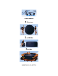
1
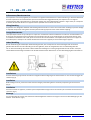
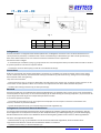
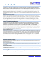
IT – EN – FR – DE
REA 025
RGA 025
ISTRUZIONI PER MONTAGGIO E MANUTENZIONE AEROREFRIGERANTI
INSTALLATION AND MAINTENANCE INSTRUCTION AIR COOLERS
INSTRUCTION PER MONTAGE ET L’ENTRETIEN EVAPORATEURS
MONTAGE UND WARTUNGSANLEITUNG VERDAMPFER
SICUREZZA - SAFETY - SECURITÈ - SICHERHEIT
SEGUIRE ATTENTAMENTE LE SEGUENTI ISTRUZIONI PER EVITARE DANNI A PERSONE E/O DANNEGGIARE IL PRODOTTO.
PAY ATTENTION TO THE FOLLOWING INSTRUCTIONS TO AVOID INJURES TO PEOPLE AND/OR DAMAGE TO THE PRODUCT.
RESPECTER ATTENTIVEMENT LES ISTRUCTIONS SUIVANTES AFIN D’EVITERDE BLESSER QUELQU’UN ET/OU
D’ENDOMMAGER L’APPAREIL.
DIE NACHFOLGENDEN ANLEITUNGEN GENAU BEFOLGEN, UM ERNSTE PERSONEN- UND/ODER GERÄTSCHÄDEN ZU
VERMEIDEN.
REA-RGA Installation manual Release 27/02/2015 - Page 1 / 8
[email protected] – www.refteco.com
IT – EN – FR – DE
Condizioni della Garanzia
Quest’apparecchiatura è progettata per operare correttamente e produrre la capacità specificata quando installata
conformemente agli standard industriali. La garanzia che copre l’impianto decade qualora non siano rispettate le condizioni
descritte di seguito.
1. Installare le connessioni idrauliche a regola d’arte seguendo gli standard industriali.
2. Caricare gas inerte nelle tubazioni durante le operazioni di saldatura.
3. Verificare che il sistema sia completamente privo di perdite prima di caricarlo.
4. L’alimentazione al sistema deve rispettare i seguenti requisiti:
a) 230/400V +/- 5% 50Hz; 276/480V +/-5% 60Hz
b) L’assorbimento di corrente per fase sbilanciata non deve superare il 2%.
Warranty conditions
This equipment is designed to operate properly and produce rated capacity when installed in accordance with accepted
industry standards. Failure to meet the following conditions could render the system warranty null and void:
1. System piping must be installed following industry standards for good piping practices.
2. Inert gas must be charged into piping during welding.
3. System must be thoroughly leak-checked before initial charging.
4. Power supply to system must meet the following conditions:
a) 230/400V +/- 5% 50Hz; 276/480V +/-5% 60Hz
b) Current absorption per phase imbalance not to exceed 2%.
Conditions de garantie
Cet appareil a été conçu pour fonctionner correctement et produire le rendement spécifié lorsqu’il est installé conformément
aux normes industrielles. La garantie qui couvre l’installation n’est plus valuable lorsque les conditions indiquées ci-dessous
ne sont pas respectées.
1. Installer les connexions hydrauliques dans les règles de l’art conformément aux norms industrielles.
2. Introduire du gaz inerte dans les tuyaux durant les opérations de soudage.
3. Vérifier que le système ne subit aucune perte avant de l’introduire.
4. L’alimentation du système doit respecter les caractéristiques suivantes :
a) 230/400V +/- 5% 50Hz ; 276/480V +/-5% 60Hz.
b) L’absorption de courant due au déréglage de la phase ne doit pas dépasser 2%.
Garantiebedingungen
Dieses Gerät wurde für den korrekten Betrieb mit der spezifizierten Leistung nach einer den Industrie Standardnormen
entsprechenden Installation entwickelt. Die diese Anlage deckende Garantie verfällt, wenn die nachfolgenden Bedingungen
nicht eingehalten werden.
1. Die Hydraulikanschlüsse müssen kunstgerecht unter Beachtung der Industriestandards
realisiert werden.
2. Während der Schweißungsarbeiten Inertgas in die Leitungen laden.
3. Vor dem Laden des Geräts sicherstellen, dass keine Leckagen vorhanden sind.
4. Die Stromversorgung des Systems muss folgenden Anforderungen entsprechen:
a) 230/400V +/- 5% 50Hz; 276/480V +/-5% 60Hz.
b) Die Stromaufnahme bei Phasenungleichgewicht darf nicht 2% überschreiten.
REA-RGA Installation manual Release 27/02/2015 - Page 2 / 8
[email protected] – www.refteco.com
IT – EN – FR – DE
Sollevamento/Movimentazione
Gli evaporatori sono stati progettati per consentirne un’agevole movimentazione a mezzo muletto o gru. Prestare attenzione
durante le operazioni di movimentazione per evitare eventuali danneggiamenti delle parti esposte. Per una migliore
movimentazione dell’unità posizionare le forche del muletto sulle zone adeguate del supporto in legno usato per il trasporto.
Il contatto diretto delle forche con l’apparecchiatura potrebbe causare danni alla stessa.
Lifting/Handling
Evaporators are designed to facilitate safe handling with fork trucks or cranes. Use caution when handling to prevent damage
to exposed components. Lifting forks should be placed under appropriate areas of the wooden shipping.
Levage/Manutention
Les évaporateurs ont été conçus de façon à ce que leur manutention soit facile à effectuer à l’aide d’un chariot élévateur ou
d’une grue. Être vigilant durant les opérations de manutention afin de ne pas endommager les composants exposés. Pour
une meilleure manutention de l’unité, placer les fourches du chariot élévateur aux emplacements prévus sur le support en
bois utilisé pour le transport. Un contact direct des fourches avec l’appareil pourrait endommager l’appareil.
Heben/Handling
Bei der Entwicklung der Verdampfer wurde darauf geachtet, dass sie bequem mit einem Hubwagen oder einem Kran
gehoben werden können. Beim Handling ist Vorsicht geboten, damit die ausgesetzten Teile nicht beschädigt werden.
Für ein besseres Handling der Einheit sind die Gabeln des Hubwagens an einem geeigneten Bereich der für den Transport
verwendeten Holzunterlage anzusetzen. Der direkte Kontakt mit den Gabeln kann zu einer Beschädigung der Einheit führen.
Installazione
Prima di sollevare gli apparecchi controllare l’integrità strutturale degli organi di sollevamento e il loro corretto fissaggio alla
struttura.(Fig.1)
Installation
Before lifting the units, please check the structural integrity of the lifting devices and their proper fixing to the structure.
(Fig.1)
Installation
Avant de soulever les appareils, contrôler que les dispositifs de lavage sont en bon état et qu'ils sont fixés correctement à la
structure. (Fig.1)
Montage
Vor dem Anheben der Geräte die strukturelle Vollständigkeit der Hebevor richtungen und ihre korrekte Befestigung an der
Struktur kontrollieren. (Fig.1)
REA-RGA Installation manual Release 27/02/2015 - Page 3 / 8
[email protected] – www.refteco.com
IT – EN – FR – DE
Fig. 1
REA 0251
REA 0252
REA 0253
REA 0254
A
730
1105
1480
1855
B
405
780
1155
1530
Collegamenti
Prima di procedere ai collegamenti dei collettori/distributori, è obbligatorio assicurarsi che il circuito d’alimentazione sia
chiuso (assenza di pressione). La saldatura della valvola termostatica (H) al distributore (I) e della linea di aspirazione (L),
deve essere fatta avendo cura di non indirizzare la fiamma di saldatura verso l’apparecchio.
Non devono essere collegati:
- Il manometro per le verifiche (Te, fig. 2); gli apparecchi sono muniti di apposita valvola per attacco del manometro. Alla fine
di questa operazione rimontare le coperture laterali.
- La tubazione di scarico dell’acqua (F) al tubo di scarico della bacinella (G).
Connections
Before to proceed with the collectors/distributors connections it is mandatory to comply as follows make sure the supply
circuit is closed (no pressure). The thermostatic valve (H) to distributor (I) and suction line (L), taking care to not direct gas
flame towards cooler during brazing.
They musn’t be connected.
- Pressure checks (Te, fig. 2); all units are fitted with a shrader valve on the suction pipe, so that the suction pressure can be
measured for correct operation. When all connections and adjustments have been made refit both side panels
- The water drain tubing connection (F) to drain pan tube (G).
Raccords
Avant de procéder aux raccordements des collecteurs/distributeurs, est obligatoire de s’assurer que le circuit d’alimentation
est fermé (absence de pression). La vanne thermostatique (H) au distributeur (I) et le tube (L) d’aspiration, en prenant soin de
ne pas diriger la flamme du gaz vers l’évaporateur pendant la soudure.
Ils ne doivent pas être connectés:
- Le contrôle per manomètre (Te, Fig. 2): le appareils sont équipés d’un raccord pour connecter le manomètre. Pour
terminer, remonter les panneaux latéraux.
- Le tube d’écoulement d’eau (F) à la connexion d’écoulement de l’égouttoir (G).
Collegamenti-Connections-Raccords-Anschlusse
Vor Anschluss der Sammelrohre/Verteilerrohre müssen folgende Vorschriften eingehalten werden: Sicherstellen, daß der
Druck abgelassen ist. Das Expansionsventil (H) an dem Einspritzverteiler (I) und die Saugleitung (L), unter Berücksichtigung,
daß die Gasflamme beim Löten vom Luftkühleranschluß in Richtung Rohr gehalten wird und nicht in Richtung Luftkühler.
Sie sollen nicht angeschlossen werden:
- Prüfmanometer (Te, Fig. 2); Die Luftkühler sind mit einem Schraderventil ausgestattet, wo ein Prüfmanometer
angeschlossen werden kann. Zuletzt sind die Seitenteile wieder zu montieren.
- Tropfwasseranschluß (F) an den Ablaufstutzen (G).
REA-RGA Installation manual Release 27/02/2015 - Page 4 / 8
[email protected] – www.refteco.com
IT – EN – FR – DE
Verifiche
Rilevare le seguenti temperature e pressioni:
Ts’ - Temperatura di cella nella zona aria ingresso all’evaporatore.
Te - Temperatura di evaporazione, corrispondente alla pressione refrigerante all’uscita dell’evaporatore.
Trs - Temperatura di surriscaldamento del refrigerante, sulla linea di aspirazione in prossimità del bulbo della valvola
termostatica.
N.B. - Per un utilizzo ottimizzato dell’evaporatore il surriscaldamento (Trs-Te) non dovrà superare 0,7 x (Ts’-Te).
Accertato che la valvola termostatica sia adeguata alle condizioni di impianto, compatibilmente alle pendolazioni del sistema,
mantenere il più basso surriscaldamento possibile al fine di ottenere dall’aeroevaporatore la massima potenza.
Cooler capacity checks
Take the following temperature and pressures:
Ts’ - Cold room air inlet temperature to the unit.
Te - Evaporating temperature, relating to the refrigerant pressure on the unit cooler outlet.
Trs - Refrigerant superheat temperature, on suction line near thermostatic valve bulb.
N.B. - For otimum unit cooler performance the superheat (Trs-Te) shoud not be high erthan 0,7 x (Ts’-Te).
The thermostatic valve fitted must be correctly sized for the installation conditions and adjusted for correct system
operation.
N.B. Keep the superheat as low as possible to obtain maximum unit cooler performance.
Controles
Relever les températures et pressions suivantes:
Ts’ - Témperature de la chambre froide dans la zone d’entrée d’air de l’évaporateur.
Te - Témperature d’évaporation, correspondante à la pression du réfrigérant à la sortiede l’évaporateur.
Trs - Témperature de surchauffe du réfrigérant, sur la ligne d’aspiration à proximité du bulbe de la vanne thermostatique.
N.B. - Pour utiliser l’aéroévaporateur dans les conditions optimales, la surchauffe(Trs-Te) ne doit pas être supérieure à 0,7 x
(Ts’-Te).
Si l’on s’assure que la vanne thermostatique est conforme aux conditions d’installation établies et compatible avec les
conditions de fonctionnement du système, le rendement de l’évaporateur sera d’autant plus grand que la surchauffe sera
plus faible.
Leistungsuberprufung
Folgende Temperaturen und Drücke sind zu messen:
Ts’ - Kühlraumtemperatur an der Lufteintrittsseite des Verdampfers.
Te - Verdampfungstemperatur über Druck am Verdampferende.
Trs - Fühlertemperatur an der Saugleitung nahe beim Fühler des Expansionventils.
N.B. - Für eine optimale Verdampferarbeitsweise darf die Überhitzung (Trs-Te) nicht höher sein als 0,7 x (Ts’-Te).
Das Expansionventil muß entsprechend der installerten Leistung und Betriebsbedingungen ausgewählt werden.
N.B. Die Uberhitzung soll möglichst klein gehalten werden, um die maximale Verdampferleistung zu erreichenò.
REA-RGA Installation manual Release 27/02/2015 - Page 5 / 8
[email protected] – www.refteco.com
IT – EN – FR – DE
Fig. 3
Connessioni idrauliche per unità a glicole
Sfiatare l’impianto, far fuoriuscire completamente l’aria presente e verificare che non vi siano colpi d’ariete.
Controllare il funzionamento dell’elettrovalvola di alimentazione o della valvola di miscelazione. Importante:
• Il dimensionamento delle tubazioni deve rispettare il diametro di attacco IN e OUT della batteria.
• Installare le valvole di intercettazione (ON-OFF) vicino all’unità per consentire il regolare svolgimento degli interventi
manutentivi.
• Utilizzare giunti antivibrazioni.
• Rivestire tutte le filettature con del TEFLON per assicurarne la tenuta.
Water connections for Brine units
Vent the system, bleed off all air, and check for water hammer. Verify the feed solenoid valve or mixing valve function.
Important:
• The size of the pipe must be in accordance with the IN and OUT connection diameter of the coil.
• ON-OFF valves must be installed near the unit to permit normal maintenance.
• Use vibration-damping joints;
• All threads should be covered with TEFLON to ensure air tightness.
Connexions hydrauliques pour l‘unité Brine
Purger l’installation, faire évacuer tout l’air présent et vérifier l’absence de coups de bélier.
Contrôler que l’électrovanne d’alimentation ou la vanne de mélange fonctionne correctement. Important :
• Les dimensions des tuyaux doivent respecter le diamètre du raccord IN et OUT du serpentin.
• Installer les vannes d’interception (ON-OFF) à proximité de l’unité de façon à pouvoir effectuer correctement les
interventions d’entretien.
• Utiliser les joints anti-vibrations.
• Recouvrir tous les filetages de TEFLON afin d’en assurer l’étanchéité.
Hydraulische Anschlüsse der Brine-Einheit
Die Anlage komplett entlüften und überprüfen, dass keine Druckstöße vorhanden sind.
Die Funktionstüchtigkeit des Speisemagnetventils oder des Mischventils überprüfen. Wichtig:
• Bei der Dimensionierung der Leitungen muss der Durchmesser der Anschlüsse IN und OUT des Pakets berücksichtigt
werden.
• Die Sperrventile (ON-OFF) in der Nähe der Einheit installieren, damit die Wartungsarbeiten regular durchgeführt werden
können.
• Schwingungsgedämpfte Anschlüsse verwenden.
• Alle Gewinde mit TEFLON überziehen, um die Dichtigkeit zu gewährleisten.
REA-RGA Installation manual Release 27/02/2015 - Page 6 / 8
[email protected] – www.refteco.com
IT – EN – FR – DE
Tubature per lo scarico della condensa
La linea di scarico di ogni unità va collegata al giunto gas femmina posizionato al centro della vasca di sgocciolamento e va
collegata tramite tubi a un sifone indipendente per evitare che l’aria calda passi attraverso le linee di scarico. L’inclinazione
minima non deve essere inferiore al 20%. Le connessioni della vaschetta di scarico, le linee di scarico e i sifoni che si trovano a
temperature estremamente basse devono essere tracciati con cavi elettroscaldanti e coibentati in modo da prevenirne il
congelamento. Mantenere gli elementi riscaldanti costantemente sempre sotto tensione. Supportare tutti i tubi in modo
adeguato indipendentemente dall’unità a cui sono collegati in modo da evitare di esercitare peso sulla connessione della
vaschetta. Durante lo sbrinamento, riscaldare il tubo di scarico utilizzando un riscaldatore elettrico installato all’interno del
tubo stesso.
Condensation discharge piping
The drain line for each unit should be connected to the female gas joint, located in the center of the drip tray and must be
piped to an independent trap to prevent the migration of warm air through the drain lines. The minimum slope must not be
less than 20%. Drain pan connections and any drain lines and traps that are located in freezing temperatures must be
heat traced and insulated to prevent freezing. Heating elements should be continuously energized. All piping should be
adequately supported, independently of the unit so no weight is exerted on the pan connection. During the defrosting time,
the discharge pipe should be heated by an electrical heater placed inside the pipe.
Tuyaux d’évacuation de la condensation
La ligne d’évacuation de chacune des unités doit être raccordée au joint gaz de type femelle placé au centre du plateau
d’égouttement et doit également être raccordée par des tuyaux à un siphon indépendant pour empêcher l’air chaud de
passer dans les lignes d’évacuation. L’inclinaison minimum ne doit pas être inférieure à 20%. Les connexions du bac
d’évacuation, les lignes d’évacuation et les siphons qui sont à des températures extrêmement basses doivent être tracés avec
des câbles chauffants électriques et isolés de façon à en empêcher la congélation. Toujours laisser les éléments chauffants
sous tension. Installer des supports pour tous les tuyaux, indépendamment de l’unité à laquelle ils sont raccordés, de façon à
ce que leur poids n’exerce aucune pression sur la connexion du bac. Durant le dégivrage, réchauffer le tuyau d’évacuation à
l’aide d’un réchauffeur électrique placé à l’intérieur du tuyau.
Kondensatablassleitungen
Die Ablassleitung jeder Einheit ist an den Bsp-Anschluss mit Innengewinde in der Mitte des Tropfbeckens anzuschließen. Der
Anschluss muss mittels Rohren an einen unabhängigen Siphon erfolgen, damit die heiße Luft nicht durch die Ablassleitungen
strömt. Die Mindestneigung darf nicht unter 20% liegen. Anschlüsse des Ablassbeckens, Ablassleitungen und Siphone mit
extrem niedriger Temperatur müssen mit elektrischen Heizkabeln versehen und isoliert werden, damit sie nicht einfrieren
können. Die Heizelemente immer unter Spannung halten. Alle Rohre korrekt unabhängig von der Einheit, an die sie
angeschlossen sind, abstützen, damit kein Gewicht auf dem Beckenanschluss lastet. Beim Enteisen das Ablassrohr mit einem
im Rohr selbst installierten elektrischen Erhitzer Erwärmen.
Connessioni elettriche ventilatori
Assicurarsi prima di procedere ai collegamenti elettrici che il circuito elettrico d’alimentazione sia aperto. Collegamento dei
ventilatori monofase (fig. 4).
Electric connection fan motors
Before proceeding with electrical wiring, it is essential to ensure that the power supply circuit is open. Connection 1 phase
motor see (fig. 4).
Connexion des moteurs
Avant de procéder aux raccordements électriques, est obligatoire de s’assurer que le circuit électrique d’alimentation est
ouvert. Monophasé connexion (fig. 4).
Motorsschaltugen
Vor Ausführung der Elektroanschlüsse müssen folgende Vorschriften eingehalten werden Sicherstellen, daß der
Stromversorgungskreis offen ist. Einphasig motorsschaltugen (fig. 4).
REA-RGA Installation manual Release 27/02/2015 - Page 7 / 8
[email protected] – www.refteco.com
IT – EN – FR – DE
1ph / 230V / 50Hz
Fig. 4
Sbrinamento Elettrico
Assicurarsi prima di procedere ai collegamenti elettrici che il circuito elettrico d’alimentazione sia aperto. Schema di
collegamento (fig. 5).
Electrical Defrost
Before proceeding with electrical wiring, it is essential to ensure that power supply circuit is open. Connecting wiring (fig. 5).
Dégivrage Électrique
Avant de procéder aux raccordements électriques, est obligatoire de s’assurer que le circuit électrique d’alimentation est
ouvert. Schema de raccordement (fig. 5).
Elektrische Enteisung
Vor Ausführung der Elektroanschlüsse müssen folgende Vorschriften eingehalten werden Sicherstellen, daß der
Stromversorgungskreis offen ist. Schaltbilder zeichenerklaring (fig. 5).
1ph / 230V / 50Hz
Fig. 5
Sbrinamento Elettrico - Electrical Defrost
Dégivrage Électrique - Elektrische Enteisung
Modello - Type
Modèle - Modell
230 V
(W x 1)
REA 0251 C.. – REA 0251 D..
REA 0252 C.. – REA 0252 D..
REC 0253 C.. – REA 0253 D..
REC 0254 C.. – REA 0254 D..
500
1000
1500
2000
N°
Resistenze – Heaters
Résistances - Heizstabe
1
1
1
1
TOT.
W
500
1000
1500
2000
ATTENZIONE – WARNING – ATTENTION – ACHTUNG
Bordi taglienti
Sharp edges
Bords coupants
Scharpe rander
Pericolo ustioni
Danger burns
Danger brulures
Gefahr von verbrennungen
REA-RGA Installation manual Release 27/02/2015 - Page 8 / 8
Pericolo elettricità
Danger electricity
Danger Electricité
Gefahr von strom
[email protected] – www.refteco.com