1
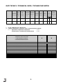
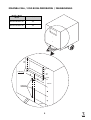
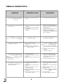
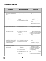
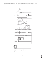
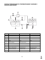
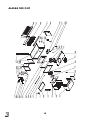
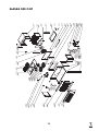
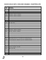
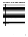
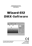
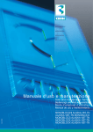
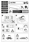
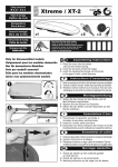
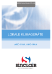
REFRIGERAZIONE
REFRIGERATION
RÉFRIGÉRATION
KÜHLUNG
Manuale d'uso e manutenzione
user and maintenance Manual
Manuel d'emploi et d’entretien
Bedienungs und Wartungsanleitung
Manual 8de uso y mantenimiento
T
10 9
6 7
Cod. - 21340
R
2
1
MONOBLOCCHI
ALASKA O BT/TN
4
ALASKA
O BT/TN MONOBLOCS
3
MONOBLOCS ALASKA O BT/TN
S BT/TN
MONOBLOCK ALASKA
S1 O
MONOBLOCK ALASKA O BT/TN
8
7
6
R
DATI TECNICI / TECHNICAL DATA / TECHNISCHE DATEN
Resa*
Tensione
Max.pot.assorbita
Potenza nominale
Capacity*
Voltage
Max.abs.power
Power raiting
Leistung*
Spannung
Max.leistungsaufn
Nennleistung
Campo applicazioni
Tipo refrigerante
Application field
Anwendungsbereich
(W)
(V-Ph-Hz)
(Kw)
Sbrinamento
Espansione
Peso netto
m3cella**
Refrigerant type
Defrost
Expansion
cold room m3**
Kä ltemittel
Abtauung
Expansion
m3 kü hlraum**
(CV)
G
Net weight
Nettogewicht
(Kg)
N
ALASKA 200 O BT
-20°C/+10°C
1800
230-1-50+N
990
1
R404 A
G
VT
73
ALASKA 240 O BT
-20°C/+10°C
2800
230-1-50+N
1745
2
R404 A
G
VT
76
G = A gas caldo/ Hot gas / Heisses Gas
VT = valvola termostatica / expansion valve / thermostatisches E.Ventil
* = N Espansione / Expansion / Expansion
= -10°C
Condensazione / Condensing / Kondensation
= +40°C
**CONDIZIONI DI CALCOLO DEI VOLUMI
B
**VOLUME CALCULATION CONDITIONS
N
**VOLUMENRECHNUNGBENDINGUNGEN
ISOLANTE-INSULATION-ISOLIERMITTEL
poliuretano-polyurethan- polyurethanschaum
SPESSORE-THICKNESS-DICKE-ESPESOR
100 MM
80 MM
CALORE SPECIFICO-SPECIFIC HEAT-SPEZIFISCHE WÄRME
0,44
0.77 Kcal/Kg°C
TEMPERATURA D’INGRESSO-INPUT TEMPERATURE-EINBRINGTEMPERATUR
-15 °C
-15 °C
DENSITÀ DI CARICO-LOAD DENSITY-DICHTE
250 Kg/m3
250 Kg/m3
MOVIMENTAZIONE-DAILY EXCHANGE-TGLICHE BEWEGUNG DER GESAMTMENGE
10%
10%
TEMPO DI RAFFREDDAMENTO-COOLING TIME--KÜHLUNGZEIT-
24h
24h
ORE FUNZIONAMENTO COMPRESSORE-COMPRESSOR WORKING HOURS-ARBEITSSTUNDEN DES VERDICHTERS
18h
18h
0°C
0°C
TEMPERATURA CELLA-COLD ROOM TEMPERATURE FROIDE-ZELLENTEMPERATUR
UBICAZIONE CELLA-COLD ROOM LOCATION-ZELLENPOSITION
INTERNO EDIFICIO-INSIDE BUILDING-GEBÄUDEINNERE
TEMPERATURA AMBIENTE-AMBIENT TEMPERATURE--RAUMTEMPERATUR
2
20÷43°C
20÷43°C
FORATURA CELLA / COLD ROOM PERFORATION / ZELLENBOHRUNG
Modello / Model
Modell
A (mm)
ALASKA 200 O BT/TN
595
ALASKA 240 O BT/TN
595
360
mm
30 mm
n°4Ø10mm
30
mm
320
mm
A
10 mm
20
mm
30
mm
400 mm
n°3Ø3,5mm
30 mm
3
TABELLA DIAGNOSTICA
ANOMALIA
PROBABILE CAUSA
INTERVENTO
1 Mettendo sotto tensione il monobloc
co il regolatore elettronico non
si
accende.
1.1 Interruttore generale in posizione
OFF.
2 Il compressore ronza ad intermittenza,
ma non si avvia.
2.1 Tensione di linea inferiore ai limiti di
tolleranza.
2.2 Collegamenti elettrici errati perchè
manomessi.
2.3 Avvolgimento del motore elettrico
difettoso.
3 Con il display acceso ed il regolatore
in posizione acceso il monoblocco
non parte.
3.1 Set point impostato superiore della
temperatura in cella.
3.1 Controllare il set point impostato ed
eventualmente diminuirlo.
4 Il compressore si arresta per l’interven
to del protettore termico.
4.1 Condensatore inefficiente.
4.2 Insufficiente flusso di aria sul conden
satore.
4.3 Ricircolo d’aria sul condensatore.
4.4 Avvolgimento del motore in corto circuito o a massa.
4.1 Pulire il pacco alettato ed eventualmente raddrizzare le alette
deforma
te con un pettine.
4.2 Verificare l’efficienza dei ventilatori,
senso di rotazione, stato delle vento
le.
4.3 Correggere la sistemazione del
monoblocco.
4.4 Sostituire il compressore.
5 Il compressore non si avvia e non si
avverte alcun ronzio, benchè al monoblocco arrivi tensione e sul regolatore
elettronico è impostato un valore di
temperatura più bassa di quella esi
stente in cella.
5.1 La linea di alimentazione del com
pressore è interrotta.
5.2 L’avvolgimento del motore elettrico è
interrotto;
5.3 Relais del regolatore elettronico guasto.
5.1 Distaccare la linea ai suoi capi e veri
ficare la sua continuità circuitale.
5.2 Verificare la continua circuitale del
l’avvolgimento, eventualmente sosti
tuire il compressore.
5.3 Sostituire il regolatore elettronico.
6.1 Evaporatore pieno di ghiaccio.
6.2 Parametri impostati errati perchè
manomessi.
6.3 Apertura porta cella a ritmi troppo
elevati.
6.4 Caldo eccessivo nel locale dove è
installato l’impianto;
6.5 Condensatore sporco.
6.6 Bobina elettrovalvola di sbrinamento
interrotta.
6.7 Relè comando sbrinamento del rego
latore elettronico guasto.
6.1 Eseguire uno sbrinamento manuale
finchè l’evaporatore non sia libero
dal ghiaccio.
6.2 Ripristinare come da tabella parametri.
6.3 Limitare l’apertura della porta cella.
6.4 Arieggiare il locale.
6.5 Pulire il pacco alettato ed eventualmente raddrizzare le alette con
un
pettine.
6.6 Sostituire bobina.
6.7 Sostituire regolatore elettronico.
6 Resa insufficiente: il monoblocco non
riesce a portare la cella al valore di
temperatura impostato.
4
1.1 Accendere l’interruttore generale.
2.1 Misurare la tensione in arrivo al
monoblocco: se inferiore ai limiti di
tolleranza richiedere l’intervento del
l’ente erogatore.
2.2 Ripristinare i collegamenti con riferimento agli schemi originali.
2.3 Verificare la continuità circuitale del
l’avvolgimento, eventualmente sosti
tuire il compressore.
TROUBLESHOOTING
LIKELY CAUSE
PROBLEM
1 When the monobloc is energised, the
electronic regulator will not
switch on.
2 The compressor buzzes intermittently
but will not start.
3 The display is lit and the regulator is in
the “on” position but the monobloc
will not start.
4 The compressor has stopped due to
termal cut-out switch intervention.
5 The compressor will not start and
there is no buzzing sound, although
power is being supplied to the mono
bloc and the temperature setting on
the electronic regulator is lower
than
that of the cold room.
6 Insufficient capacity: the monobloc
cannot bring the cold room tempera
ture to the set value.
INTERVENTION
1.1 The main switch is in the OFF position.
1.1 Switch on the main switch.
2.1 The line voltage is lower than tolerance limits.
2.2 The electrical connections are wrong
because they have been tampered
with.
2.3 The electrical motor winding is
faulty.
2.1 Measure the input voltage of the
monobloc and if lower than the
tolerance limits, request an interven
tion from your power supplier.
2.2 Restore the original connections,reffering to the original electrical diagrams.
2.3 Check the winding circuit continuity
and if necessary, replace the compressor.
3.1 The set point setting is above the
cold room temperature..
3.1 Check the set point setting and if
necessary, decrease it.
4.1
4.2
4.3
4.4
4.1 Clean the fins unit and if necessary,
straighten any bent fins with comb.
4.2 Check the working order of the
fans, their rotation direction and
state.
4.3 Move the monobloc to a more suitable location.
4.4 Replace the compressor.
Condenser inefficient.
Insufficient air flow to the condenser.
Air recirculation on the condenser..
The motor winding has short circuited or earthed.
5.1 The power supply to the l compres
sor has been cut off.
5.2 The electrical motor winding has
been cut off.
5.3 The electronic regulator relay switch
is faulty.
5.1 Disconnect the line at its ends and
check its circuit continuity
5.2 Check the continuity of the winding
circuit and if necessary, replace the
compressor..
5.3 Replace the electronic regulator.
6.1 The Evaporator is full of ice.
6.2 The set parametersare incorrect due
to tampering.
6.3 The cold room door is being opened
too often.
6.4 The area where the system has been
installed is too hot.
6.5 The condenser is dirty.
6.6 The defrost solenoid valve coil has
been cut off.
6.7 The defrost control relay switch of
the electronic regulator is faulty.
6.1 Carry out a manual defrost cycle
until the evaporator is free of ice.
6.2 Restore the parameters as shown in
the relative table.
6.3 Limit cold room door opening.
6.4 Air the premises.
6.5 Clean the fins unit and if necessary,
straighten the fins with a comb.
6.6 Replace the coil.
6.7 SReplace the electronic regulator.
5
DIAGNOSETABELLE
STÖRUNG
MÖGLICHE URSACHE
BEHEBUNG
1 Bei Stromzufuhr zum Monoblock
schaltet sich der elektronische Regler
nicht ein.
1.1 Hauptschalter Regler aut OFF.
1.1 Den Hauptschalter Regler einscalten.
2 Der Kompressor brummt unre
gelmäßig, schaltet aber nicht ein.
2.1 Stromzufuhr unter der min. Grenze
2.2 Stromanschluss wegen Manipulation
fehlerhft.
2.3 Wicklung des Elektromotors defekt.
2.1 Die Eingangsspannung zum
Monoblock messen:wenn unterhalb
der min.
2.2 Die Verbindungen entsprechend der
Ausgangskonfiguration wiederher
stellen.
2.3 Die Kreislaufkontinuität der
Wicklung prüfen, gegebenen
falls den Kompressor austauschen.
3 Bei eingeschaltetem Display und
Regler starter der Monoblock nicht.
3.1 Eingestellter Set-Point über der
Zellentemperatur.
3.1 Den eingestellen Set-Point prüfen
und gegebenenfalls verringern.
4 Der Kompressor wird durch den
Wärmeschutz ausgeschaltet.
4.1 Fehlerhafter Kondensator.
4.2 Ungenügender KLuftstrom am
Kondensator.
4.3 Luftumwälzung am Kondensator.
4.4 Motorwicklung in Kurzschluss oder
geerdet.
4.1 Kühlrippen reinigen und verbogene
Rippen mit Kamm begradigen.
4.2 Ventilator prüfen; Rotationsrichtung,
Zustand der Flügel.
4.3 Die Position des Monoblocks korrigieren.
4.4 Kompressor austauschen.
5 Der Kompressor startet nicht und gibt
keine Geräusche von sich, obwohl der
Monoblock unter Spannung steht und
auf dem elektronischen Regler eine
niedrigere Temperatur, als in der Zelle
vorhanden, eingestellt ist.
5.1 Die Stromversorgung zum
Kompressor ist unterbrochen.
5.2 Die Motorwicklung ist unterbrochen.
5.3 Relais des elektronischen Reglers
defekt.
5.1 Die Leitung an den Enden unterbre
chen und die Kreislaufkontinuität
prüfen.
5.2 Die Kreislaufkontinuität der
Wicklung prüfen,gegebenenfalls
den Kompressor austauschen.
5.3 Den elektronischen Regler austau
schen.
6.1 Verdampfer durch Eis blockiert.
6.2 Falsche Parameter durch
Manipulation.
6.3 Die Zellentür wird zu häufig geöffnet.
6.4 Die Raumtemperatur des
Installationsorts zu hoch.
6.5 Kondensator verschmutzt.
6.6 Spule des Abtau-Elektroventils unter
brochen.
6.7 Abtau-Steuerrelais des elektronischen
Reglers defekt.
6.1 Manuelles Abtauen, bis der
Verdampfer vom Eis befreit ist.
6.2 Die Parameter der Tabelle entsprechend wiederherstellen.
6.3 Die Zellentür seltener öffnen.
6.4 Den Raum lüften.
6.5 Kühlrippen reinigen und gegebenen
falls die Rippen mit einem
Kamm
begradigen.
6.6 Spule austauschen.
6.7 Elektronischen Regler austauschen.
6 Unangemessene Leistung: der
Monoblock bringt die
Zellentemperatur nicht auf die
Temperaturvorgabe.
6
7
LC
S1
N
L1
F1
3
1
X21
BT2
11
BT1
10
X20
A
X22
12
X18
RS
X19
X3
P.B.
X2
P.A.
X1
15
13
K1
A
1
X9
BLUE
M4
X6
1
X7
BROWN
START
START
P.C.
K1
M2
X8
BLACK
X5
X4
22
21
X10
1
2
R
S
M1
C
K2
X12
X11
3
2
D1
RUN
START
RUN
X14
Y1
X13
23
22
A
X16
BLUE
1
M3
X15
BLACK
19
17
A
START
X17
BROWN
SCHEMA ELETTRICO ALASKA O BT/TN 200-240 230-1-50Hz
POWER 230V
LEGENDA SCHEMA ELETTRICO / ELECTRICAL DIAGRAM LEGEND/
SCHALTPLANLEGENDE
DESCRIZIONE-DESCRIPTION-BESCHREIBUNG
A1
Centralina elettronica-Electronic control system-Elektronische Steuerung
BT1
Sonda temperatura ambiente-Ambient temperature probe-Raumtemperaturfühler
BT2
Sonda sbrinamento elettrico-Electrical defrost probe-Abtautemperaturfühler
K1
Relè compressore-Compressor relay-Kompressorrelais
Lc
Luce cella-Cold room light-Zellenlampe
L1-N
Alimentazione-Alimentation-Versorgung
M1
Compressore-Compressor--Kompressor
M2/M4
Ventilatore condensatore-Condenser fan-LÜfter Kondensator
M3/M5
Ventilatore evaporatore-Evaporator fan-LÜfter Verdampfer
Pa
Pressostato alta pressione-High pressur pressostat-Hochdruck-Druckwächter
Pb
Pressostato bassa pressione-Low pressure pressostat-Niederdruck-Druckwächter
Pc
Pressostato controllo condensazione-Pressostat for condensation control-Kondensat-Druckwächter
S1
Interruttore luce cella-Room light switch-Lichtsschalter
S2
Interruttore generale-Main switch-Hauptschalter
Y1
Solenoide-Solenoid-Magnetventil
X
Morsettiera-Terminal strip-Klemmleiste
Rs
Resistensa - Resistance - Widerstand
D1
Condensatore - Condenser - Kondensator
8
SCHEMA TERMODINAMICIO /THERMODYNAMIC DIAGRAMS /
SCHALTPLANLEGENDE
1
10
5
9
8
4
2
6
ITA
3
7
GB
D
1
COMPRESSORE
COMPRESSOR
KOMPRESSOR
2
VENTIL. COND.
VENTILAT.COND.
VENTIL.KONDENS.
3
CONDENSATORE
CONDENSER
KONDENSATOR
4
FILTRO
DRYER
FILTER
5
SPIA DI LIQUIDO
LIQUID PILOT LIGHT
6
ORGANO DI ESPANSIONE
EXPANSION UNIT
AUSDEHNUNGELEMENT
7
EVAPORATORE
EVAPORATOR
VERDAMPFER
8
VENTIL. EVAPORATORE
EVAPORATOR FAN
VERDAMPFERVENTIL.
9
VALVOLA SOLENOIDE
SOLENOID VALVE
MAGNETILVENTIL
10
VALVOLA DI NON RITORNO
PRESSURELIEF VALVE
DRUCKBEGRENZUNGSVENTIL
9
ALASKA 200 O BT
13009
13622
14611
15815
24952
24970
04768
24986
24874
10682
16979
11132
14546
02671
11648
15355
25872
12114
24940
25873
03644
24845
24953
24951
21444
11648
24744
12794
12793
10544
12868
24271 24936
24742
19831
04767
19833
25190
24974
00227
00226
15356
24933
25191
24948
24934
23067
21388
05007
24558
06677
10
11
24874
24971
16714
24970
24952
15815
14600
13622
13009
10682
16979
11132
14546
02671
12114
15355
25872
11648
24875
25873
24845
24953
24951
21444
03644
24744
12794
12793
10544
12868
11848
24271 24936
24742
05007
24558
06677
24934
23067
21388
24948
25191
24933
15356
00226
00227
24974
25190
19833
04767
19831
ALASKA 240 O BT
ELENCO DELLE PARTI / EXPLODED DRAWING / ESARTZTEILLISTE
CODICE
CODE
KODE
DESCRIZIONE
DESCRIPTION
BESCHREIBUNG
11848
Motore - Motor - Motor
00226
Lampadina - Light bulb - Lampe
00227
Plafoniera - Lamp holder - Deckenleuchte
12793
Condensatore - Condenser - Kondensator
12794
Condensatore - Condenser - Kondensator
12868
Condensatore - Condenser - Kondensator
11648
Motore - Motor - Motor
02671
Valvola solenoide - Solenoid valve - Ventil
10544
Condensatore - Condenser - Kondensator
24744
Relè - Relay - Relais
05007
Spina fissa - Fixed plug - fester Stift
23067
Relè - Relay - Relais
06677
Tastiera elettronica - Electronic button pad - elektronische Tastatur
04768
Condensatore - Condenser - Kondensator
16714
Condensatore - Condenser - Kondensator
04767
Evaporatore - Evaporator - Verdampfer
10682
Filtro - Dryer - Filter
11132
Connettore - Connector - Anschluss
12114
Pressostato bassa pressione - Low-pressure pressostat - Niederdruck-Druckwächter
13009
Pressostato bassa pressione - Low-pressure pressostat - Niederdruck-Druckwächter
15815
Valvola limitatrice di pressione - Pressurerelief valve - Druckbegrenzungsventil
13622
Pressostato alta pressione - High-pressure pressostat - Hochdruck-Druckwächter
14546
Bobina - Coil - Spule
24974
Evaporatore - Evaporator - Verdampfer
24271
Valvola termostatica - Expansion valve - Expansionventil
15355
Sonda rossa - Red probe - roter Fühler
15356
Sonda rossa - Red probe - roter Fühler
25873
Griglia - Grid - Gitter
16979
Spia di liquido - Liquid pilot light - Flüssigkeitsanzeige
25872
Griglia - Grid - Gitter
24742
Scatola elettrica - Electric components - Elektrische bestandteile
24558
Interruttore - Switch - Schalter
12
ELENCO DELLE PARTI / EXPLODED DRAWING / ESARTZTEILLISTE
CODICE
CODE
KODE
DESCRIZIONE
DESCRIPTION
BESCHREIBUNG
24934
Tampone - Pad - Puffer
24933
Lamiera copri tampone - Sheet metal pad cover - Pufferabdeckung
19833
Boccaglio aria - Fan air nozzle - Mundstück für Luft aus Gebläse
19831
Mantello evaporatore - Evaporator skirt - Verdampferummantelung
24953
Schiena - Backboard - Rückteil
24971
Staffa - Bracket - Klammer
24952
Fianco sx - Left side - Seintenteil links
24951
Fianco dx - Right side - Seintenteil rechts
25190
Staffa - Bracket - Klammer
24986
Staffa - Bracket - Klammer
24874
Copertura frontale - Front cover - Frontabdeckung
24875
Boccaglio aria - Fan air nozzle - Mundstück für Luft aus Gebläse
24940
Boccaglio aria - Fan air nozzle - Mundstück für Luft aus Gebläse
24936
Copri foro evaporatore-Evaporator hole cover-Abdeckung Verdampferloch
24845
Telaio compon. elett. - Elettric compon. frame - Halterung für elec.
14611
Compressore-Compressor-Kompressor
14600
Compressore-Compressor-Kompressor
21388
Interruttore-Switch-Schalter
24948
Polistirolo-Polystyrene-Polystyrol
24970
Staffa - Bracket - Klammer
03644
Griglia-Grid-Gitter
25191
Staffa - Bracket - Klammer
21444
Copertura scarico-Drainage system cover-Abflußabdeckung
13
E-mail: [email protected]
I Marchi "CIBIN" - "POLOFIN" sono Depositati.
CIBIN s.r.l.
V i a A p p i a , 8 - 3 0 1 73 M e st r e / Ve n e z i a - ITa l y - Te l . 0 03 9 ( 0 ) 4 1 5 3 1 5 6 6 6 r. a . - Fa x . 0 03 9 ( 0 ) 4 1 5 3 1 5702