1
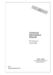
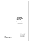
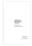
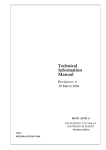
PSControl 1.4 user manual
Lorenzo Masetti <[email protected]>
September 2, 2005
Contents
1
What is PSControl
1
2
How to install PSControl
2
2.1
Distributions
2
2.2
Installing on Linux
2.3
Installing on Windows
3
. . . . . . . . . . . . . . . . . . . . . . . . . . .
. . . . . . . . . . . . . . . . . . . . . . . .
. . . . . . . . . . . . . . . . . . . . . .
User manual
Login into the system and conguration
3.2
Controller
. . . . . . . . . . . .
3
. . . . . . . . . . . . . . . . . . . . . . . . . . . . .
3
3.2.1
Expert mode
3.2.2
Menu reference
Logging
3.3.1
3
3
3.1
3.3
2
. . . . . . . . . . . . . . . . . . . . . . .
5
. . . . . . . . . . . . . . . . . . . . . .
5
. . . . . . . . . . . . . . . . . . . . . . . . . . . . . .
6
Format of log les . . . . . . . . . . . . . . . . . . . . .
6
3.4
CSV Viewer . . . . . . . . . . . . . . . . . . . . . . . . . . . .
7
3.5
Global Control
8
. . . . . . . . . . . . . . . . . . . . . . . . . .
4
Setting home directory
8
5
Conguration of the branch controllers
8
6
Logging from command line
9
7
Project home page
11
1 What is PSControl
PSControl
is an application which provides a user-friendly interface for the
control of the power supplies (PSU) of the CMS Silicon Strip Tracker.
2 How to install PSControl
2
The application controls and monitors, via TCP/IP, the channels attached to a CAEN SY1527 (or SY2527) controller, and can be used in the
laboratory in place of the CAEN built-in textual interface accessible via
TELNET.
PSControl is written in C++ and Java, can be installed both on Linux
and Windows, and provides the capability of logging to CSV
1
les the values
monitored from PSU channels, for later graphical visualization.
The interface is divided into four tabs, corresponding to four main functions:
•
The rst tab is the controller, which provides a user friendly interface
to control the PSU's, by setting and monitoring their parameters.
•
The second tab is the logger, which provides a visual interface to program the logging of the values to CSV les. The user can choose the
channels to be monitored and the logging frequency.
•
The third tab is a utility for the graphical visualization of the logged
CSV les.
•
The fourth tab allows to control several PSU at a time
2 How to install PSControl
2.1 Distributions
The project is provided in in three precompiled versions:
•
For CERN Red Hat 7.3 Linux (compiled with gcc 2.96)
•
For Fedora Core 3 Linux (compiled using gcc 3.4.2)
•
For Microsoft Windows (compiled using MinGW - Minimalist GNU for
Windows)
2.2 Installing on Linux
Extract the archive and put the resulting directory where you want. Change
to that directory and type
./setPSControl.
This will set in bin/PSControl
the complete path of the application. You may want to add bin directory to
1 comma separated values
2.3
Installing on Windows
3
your path or to make a symbolic link in order to start the system by just
typing 'PSControl'.
Java 1.5.0 is needed to execute the precompiled packages: if you don't
have it available on your system you need to install the distribution with
JRE 1.5 included. If you have JRE 1.5 already installed on your system, edit
le java/MainPanel to be sure that JAVABIN contains the complete path to
the java binary.
2.3 Installing on Windows
The project is distributed for Windows in a zipped le.
If you download the distribution with JRE included you can just extract
it to a directory and start the system by double clicking on PSControl.bat
(you can put a shortcut on your desktop).
If you download the light distribution (without JRE), edit PSControl.bat
in folder java and set the variable JAVA to the absolute path to the java
executable.
3 User manual
3.1 Login into the system and conguration
The rst time the program runs, the user is asked to enter the IP address
of the SY2527 (or SY1527), a username and a password. These values are
saved to the le
.jpowerrc
2
in the user's home directory .
Then the user must choose a directory where the log les will be saved.
This value is saved to the le
.pslogdir
in the home directory.
3.2 Controller
The controller (rst tab of the GUI) is used to cotrol the PSU's. At startup
the PSU's connected to the system are found, and the state of the system
is shown, divided into slots (each slot corresponds to a dierent branch controller which can control up to 6 crates), each one divided in several PSU's.
The default PSU model is A4601F; see section 5 if you want to change the
default or if you are using mixed PSU models.
When a Power Supply Module is plugged or unplugged, in order to detect
the changes, the menu System - Rescan must be used.
2 Home directory is the value of user.home property in JAVA. Under a Windows environment this is ususally c:\documents and settings\username
3.2
Controller
4
Figure 1:
Controller panel
Each PSU has ve channels: the rst channel controls the general properties of the PSU and is shown on top of the PSU tab. Four more channels
(two low voltages and two high voltages) are shown below.
PSU's and channels have names that the user can change: these names
are saved in the controller and are visible from the CAEN built-in telnet
textual interface as well. It is recommended to change these names to reect
the current system conguration (e.g.
the PSU's can be named 'Wire 1',
'Wire 2' and the channels 'LV0', 'LV1', 'HV0', 'HV1').
In order to use the channels of a PSU the user must put the PSU in the
ready state by locking and enabling it. When a PSU is ready it's possible
to turn its channels on by clicking on the button On. Notice that, since for
the CMS SST, the two LV channels are NOT independent, only one button
is available.
The state of the PSU and of its channels is shown through trac lights.
When the PSU is not enabled all the trac lights are completely o. When
the PSU is in the ready state, all trac lights turn to yellow. When a channel
is turned on its trac light becomes green. If there is an alarm aecting one
channel, its trac light becomes red.
A general trac light is always visible on top of the interface and shows
the state of the system. It is o if all the PSU's are not ready. It is yellow
3.2
Controller
5
Figure 2:
Interface for an alarm
if at least one PSU is ready but no channel is on. It is green if at least one
channel is powered on. It is red if there is an alarm anywhere. If there is
an alarm, the tabs of the slot(s) and of the PSU(s) where the alarm is set
are highlighted in red, so it is easy to reach the tab of the channel with the
alarm set on.
3.2.1
Expert mode
At startup the controller is set in non-expert mode. If expert mode is not
enabled, the user can only lock, unlock, enable and disable the PSU and turn
on and o the channels. To enable expert mode, use the menu Options Expert Mode.
In expert mode it is possible to change the settings of all
the writeable channels (V0Set,I0Set, SVMax, Trip, RUp, RDwn). Be careful
when you use expert mode because you can set the parameters to potentially
dangerous values for the system.
3.2.2
Menu reference
These are the commands available through menus.
•
Menu System:
Rescan rescan the system to look for new connected PSU's.
It is
necessary to rescan the system when a Power Supply Module is
plugged or unplugged.
3.3
Logging
6
Show version show version of the CAEN HVWrapper library used to
connect to SY1527 / SY2527.
Show system properties Show the values of some system properties.
Exit Exit the interface
•
Menu Options
Expert mode Enable / disable expert mode (see 3.2.1)
Set refresh Set the monitoring frequency. Default is 700 milliseconds
Set log directory Set the directory to save log les. This value is
saved in
•
.jpowerrc
le in your home directory.
Commands menu
Clear alarms Clear all the alarms of the system
HW Reset Send Hardware Reset signal to a slot (be careful!)
3.3 Logging
The second tab is a graphical interface that allows an easy use of the program
ps_log, a command line tool used for logging purposes.
By the graphical interface, the user can choose either to log all the channels of the connected PSU's, either to log all the channels of the system
regardless if they are connected or not, or to manually choose the channels
to be logged (use CTRL to select more than one channel).
It is possible to set the interval of time between two readings of the
state of the system, and to choose if the output must be verbose (i.e. write
something every time the state of the system is logged). The log program
can be started and stopped by two buttons. If you close the interface while
the logging program is still running, it will keep on running so that you'll
need later to kill the ps_log process manually.
3.3.1
Format of log les
Log les are saved to the logging directory.
A subdirectory is created for
each day. In the subdirectory of a given day there are several CSV les in
comma separated value format.
This format can be read by almost every
spreadsheet (Excel, OpenOce Calc, etc...). The names of the les are:
slotnumber_channelnumber_psuname_channelname.csv
3.4
CSV Viewer
7
Figure 3:
CSV viewer interface
For the main channel of the PSU the channel name is Main.
Channel numbers are displayed in the controller tab for each PSU and
for each channel. Remember that the rst channel of every CPU contains
the general information about the PSU, such as value of Lock, Stdby, Temp1
and Temp2. The rst row of every CSV le gives the headers, i.e. the names
of the parameter logged in each column.
These les are used to plot the graphs with the CSV viewer tool, included
in this package
3.4 CSV Viewer
The third tab is a utility to display graphically the values saved in log les.
To browse the logged les, click on a day and then on a channel name. For
each le, the names of all the elds are shown. Select the elds you want to
plot (using CTRL to select more than one eld) and then click Show graph.
The graph is displayed at the bottom of the window. It is possible to open
it in a new window in order to view more than one plot and to be able to
attach one plot to the other.
Plots are built using the values read at the time you opened the channel.
To update the values by re-reading the le, use the Reload values button.
To build plots using information from dierent channels, open one channel
of the type you are interested in and set up the plot for that channel by
choosing the desired inputs. Then click on Add other channels and choose
the other channels you want to add to the plot.
It is possible to write
3.5
Global Control
8
a pattern for easily choosing all the interested channels.
For example by
writing LV0 and clicking on Select, all the channels whose names contain
LVO (i.e. all the rst low voltage channels if you have used a consistent
naming) will be selected. In order to select all the main channels, just type
Main and click on Select.
It is possible to repeat this task for dierent
patterns and click on Add to selection in order to get the nal selection.
If the elds plotted in the graph are not present in a selected channel, that
channel will be ignored without displaying any error message.
3.5 Global Control
From the fourt tab it is possible to control more than 1 PSU. At the top of
the panel you can choose the PSU's you want to control (use CTRL to select
more than one).
Tha avaiable commands are LOCK ENABLE and DISABLE UNLOCK,
LV ON, LV OFF, HV ON and HV OFF. It is also possible to change the
values of I0Set and V0Set of the HV channels.
4 Setting home directory
To change the home where to look for conf les , add in java/MainPanel
(Linux) or java/PSControl (Windows) the option
-Dhome="path/to/the/dir"
to the last line, which starts the program.
5 Conguration of the branch controllers
Each branch controller is a slot on the main interface. All the PSU controlled
by the branch controller are shown in the same Slot.
Two dierent types of PSU's are implemented:
A4601F With lock and standby parameters
A4601H Without lock and standby parameters
The types of the PSU's are determined as follows: rst the application
checks if there is an XML le for the conguration of the slot. This le must
be placed in directory
.xml_branch
for Linux or
xml_branch for Windows
C:/Documents and
under the home directory (under Windows it is usually
6 Logging from command line
Settings/username,
must be named 0.xml
9
see 4 if you want to change the home directory) and
...
16.xml depending on the slot number. The XML
le should be created with CAEN Easy Rack Builder and should contain the
right number of PSU.
If this le is not found for a slot, or its format is invalid the default PSU
type is used.
To change the default type of PSU to A4601H, go in
(Linux) or
java/PSControl
java/MainPanel
(Windows) and change the option
-Dpsumodel="A4601F"
to
-Dpsumodel="A4601H"
in the last line, which starts the program.
6 Logging from command line
The command line tool
ps_log (3.3) can be used without opening the inter-
face.
This program uses the shared libraries provided in the package, so before
using it, be sure that they are included in your path.
Under Linux you have to set variable
LD_LIBRARY_PATH
to include lib/
subdirectory.
Under Windows you have to set variable
PATH
to include the lib/ folder.
The program takes a single argument, which is the path of a simple
le that sets all the options. If
named
config.xml
ps_log
XML
is started without arguments a le
is searched in the current directory.
An example of conguration le is provided in directory
ps_log_examples.
<!- this is an example config file for ps_log --->
<ip>172.16.1.113</ip>
<login>user</login>
<password>user</password>
<interval>10</interval>
<maindir>/tmp/newlog/</maindir>
<fast>no</fast>
<headers>yes</headers>
<verbose>yes</verbose>
<!-- in channels.xml you must provide the channels you want to log -->
<channels>channels.xml</channels>
6 Logging from command line
10
Here is a description of all the parameters
ip IP Address of the SY1527 / SY2527 System
login Login to the system
password Password to the system
interval Interval of time between two readings. In seconds.
maindir Root dir where to save log les. Subdirectories will be created for
each day.
channels (not mandatory - default <maindir>/channels.xml) Path
to another XML le which sets the channels to log.
fast (not mandatory - default no) Use a fast reading of the values. Fast
reading only reads the connected channels. It is safer to use the slow
reading.
headers (not mandatory - default yes) Set to yes to write the headers
on top of CSV les, to no to write only the values without headers
verbose (not mandatory - default yes) If verbose is yes the list of written
les is written to stdout.
Parameter channels is the path of another XML le where are listed the
channels to log.
The format of this le, that
can change while the log program is
running, is as follows
<slot number="0">
<ch>10</ch>
<ch>11</ch>
</slot>
<slot number="1">
<ch>15</ch>
<ch>16</ch>
</slot>
In this example channels 10 and 11 of slot 0 and 15 and 16 of slot 1 are logged.
These les are both generated by the visual interface so you don't need to
use them directly if you don't need to use the program from command line.
7 Project home page
11
7 Project home page
the project home page, where you can ll a form to download the project,
download the user manual and check for updates is
http://hep.fi.infn.it/CMS/PSU/