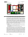
1
Technical
Information
Manual
Revision n.0
5 July 2007
MOD. A4600
EASY4000 INTERLOCK
MANUAL REV. 0
NPO:
00110/06:A4600.MUTx/00
CAEN will repair or replace any product within the guarantee period if the Guarantor declares that the
product is defective due to workmanship or materials and has not been caused by mishandling,
negligence on behalf of the User, accident or any abnormal conditions or operations.
CAEN declines all responsibility for damages or
injuries caused by an improper use of the Modules due
to negligence on behalf of the User. It is strongly
recommended to read thoroughly the CAEN User's
Manual before any kind of operation.
CAEN reserves the right to change partially or entirely the contents of this Manual at any time and without
giving any notice.
Disposal of the Product
The product must never be dumped in the Municipal Waste. Please check your local
regulations for disposal of electronics products.
PRELIMINARY
Document type:
User's Manual (MUT)
Title:
EASY4000 Interlock
Revision date:
05/07/2007
Revision:
0
TABLE OF CONTENTS
1.
2.
EASY EMBEDDED ASSEMBLY SYSTEM ............................................................................................4
1.1
FUNCTIONAL DESCRIPTION .....................................................................................................................4
1.2
THE CAEN MULTICHANNEL POWER SUPPLY SYSTEM OVERVIEW ........................................................5
1.3
THE MOD. A1676A BRANCH CONTROLLER OVERVIEW .........................................................................7
EASY4000 INTERLOCK...........................................................................................................................8
2.1
INTERLOCK AT BOARD LEVEL .................................................................................................................8
2.2
INTERLOCK AT CRATE LEVEL ..................................................................................................................8
2.3
RESET .....................................................................................................................................................8
2.4
A4600 FRONT PANEL COMPONENTS .......................................................................................................9
LIST OF FIGURES
FIG. 1.1 – SYSTEM’S BLOCK DIAGRAM ...................................................................................................................5
FIG. 2.1 – A3009 FRONT PANEL ............................................................................................................................9
FIG. 2.2 – MAIN CONNECTOR ...............................................................................................................................10
LIST OF TABLES
TABLE 1.1 – TECHNICAL SPECIFICATIONS OF THE SY 1527 MAINFRAME ...............................................................6
NPO:
00110/06:A4600.MUTx/00
Filename:
A4600_REV0.DOC
Number of pages:
10
Page:
3
PRELIMINARY
Document type:
User's Manual (MUT)
Title:
EASY4000 Interlock
Revision date:
05/07/2007
Revision:
0
1. EASY Embedded Assembly System
1.1
Functional description
EASY (Embedded Assembly SYstem) is the new CAEN power supply solution for
operation in magnetic field and radioactive environment. CAEN has been involved for
more than a decade in developing different solutions for the main LHC experiments,
where the electronic equipment of the experiment is dealing with high dose radiation and
intense magnetic field. In order to provide safe and reliable operations in such hostile
areas, CAEN started tests with rad-tolerant components and magnetic field resistant
solutions, patenting the new technology that is now used in this new line of products.
Moreover, though designed for harsh environment, the EASY modules can work also in
normal condition with excellent performance. In the new architecture, the power supply
can be located directly in the hostile area, where the EASY modules provide a wide
variety of output voltages to satisfy the requirements of most detectors and front-end
electronics. The control of the EASY power supply system is done remotely using a
Branch Controller (Mod. A1676A) plugged in a SY1527 or SY2527 mainframe located in
the control room. Each A1676A branch controller can handle up to 6 EASY crates: in this
way, one SY1527 power supply system, for example, housing up to 16 A1676A boards,
can handle up to 96 EASY systems. The EASY crate can house up to 10 boards,
depending on the boards’ width. The branch controller is the interface between the
mainframe (SY1527 or SY2527) and the remote boards in the EASY crate: its role is to
configure the EASY channels as if they belong to the supply unit slot in which the branch
controller is located. All the channels of the EASY boards are considered as channels of
the branch control board, thus hugely increasing the number of channels the system can
handle. Through the mainframe, the provided and fully reliable OPC server permits an
immediate and “automatic” interfacing with the custom control software; moreover, a
C-library for Windows and Linux is available as well. The EASY crate can be used with
an air and/or water intercooler and its standard width fit the rack mounting. Fig. 1.1
shows the system’s block diagram.
NPO:
00110/06:A4600.MUTx/00
Filename:
A4600_REV0.DOC
Number of pages:
10
Page:
4
PRELIMINARY
Document type:
User's Manual (MUT)
Title:
EASY4000 Interlock
Revision date:
05/07/2007
CONTROL ROOM
Revision:
0
HOSTILE AREA
Power Line
SY1527
48V
POWER
SOURCE
48V
SERVICE
POWER
SOURCE
CONTROL
LOGIC
POWER FAILURE
INTERRUPT
DC-DC
V+
S+
SV-
DC-DC
V+
S+
SV-
DC-DC
V+
S+
SV-
DC-DC
V+
S+
SV-
DC-DC
V+
S+
SV-
DC-DC
V+
S+
SV-
EASY Module
P. Service Line
BRANCH
CONTROLLER
CONTROL
LOGIC
SY1527 SYSTEM MAINFRAME
Control Bus
EASY Module
48V
BACKUP
BATTERY
Fig. 1.1 – System’s block diagram
1.2
The CAEN Multichannel Power Supply System Overview
The SY1527 system is the fully equipped experiment version of a new line of power
supply systems which represent CAEN's latest proposal in the matter of High Voltage
and Low Voltage Power Supplying. This system outlines a completely new approach to
power generation and distribution by allowing the housing, in the same mainframe, of a
wide range of boards with different functions, such as High/Low Voltage boards, generic
I/O boards (temperature, pressure monitors, etc.) and branch controllers, where the latter
are used to control other remote generators and distributors. Modularity, flexibility and
reliability are the key-points of its design, enabling this module to meet the requirements
needed in a wide range of experimental conditions, which range from those of LHC
experiments, where the features of this model find prior application, to those of other less
challenging, but still demanding, High Energy Physics experiments.
The mainframe is housed in a 19"-wide, 8U-high euro-mechanics rack and hosts four
main sections:
- the Board Section, with 16 slots to house boards, distributors and branch controllers;
- the Fan Tray Section, housing 6 fans arranged on two rows;
- the Power Supply Section, which consists of the primary power supply and up to 3
power supply units;
- the CPU and Front Panel Section which includes all interface facilities.
The User Software Interface features the usual friendliness of the previous CAEN
systems which now also includes a 7.7" colour LCD. A wide choice of interface facilities
provides full communication compatibility with the previous systems and the feasibility of
controlling heterogeneous external devices. Modularity has been one of the leading
criteria in the design and development of the system: both the Power Supply Section and
the Board Section are completely modular. The Power Supply Section allows different
configurations with up to 3 power supply units per mainframe (up to 2250 W), while the
Board Section can house up to 16 boards able to fulfil different functions. A complete line
of power supply boards and distributors has been specially developed for this new
system. The minimum system configuration consists of the primary power supply, one
Power Supply Unit and one board. The system allows also to deal with power supply
NPO:
00110/06:A4600.MUTx/00
Filename:
A4600_REV0.DOC
Number of pages:
10
Page:
5
PRELIMINARY
Document type:
User's Manual (MUT)
Title:
EASY4000 Interlock
Revision date:
05/07/2007
Revision:
0
solutions composed by “branch controllers” (housed in the system main frame) and ondetector “remote boards” (manufactured in order to be magnetic field and radiation
tolerant). Channel trip control on other crates is performed via four external differential
trip lines. A sophisticated trip handling via software allows to control and correlate trip
conditions on the channels of the crate as well as of other crates connected to it. Live
insertion and extraction of the boards, which reduces the down time of the global system,
and easy access to the computing core and peripherals of the system complete the
system flexibility. Easy interfacing is another key-point of the SY1527 system, which can
be connected to SY127 and SY527 systems. The Ethernet interface (TCP/IP) allows both
an easy Telnet access and the connection via OPC Server to a SCADA control system.
Enhanced software programming features a unified command set independent from the
interface used to communicate with the system. The Power Supply Section and Board
Section can be externally synchronised via front panel connectors. Multi-layered access
to the system via Intranet is foreseen through the management of several custom user
profiles. In particular, three different access levels have been implemented: Guest, User
and Administrator, each of which with password protection. Handy maintenance and
upgrading, which constitute a major issue in the reliability of a system, are further
guaranteed by the possibility of accessing and servicing the system via network facilities.
Actually, the Telnet access facility allows remote debugging and technical support of the
system, including future firmware upgrading. For a detailed description of the SY 1527
Universal Multichannel Power Supply System please refer to the SY 1527 User's Manual.
Table 1.1 – Technical specifications of the SY 1527 mainframe
Packaging
- 19"-wide, 8U-high Euro-mechanics rack;
- Depth: 720 mm.
Weight
-Mainframe (*): 24 kg
-Mod. A1532: 3.2 kg
Voltage range: 100/230 V
Power requirements
Frequency: 50/60 Hz
Power: 3400 W
Max. number of boards per crate
16
Max. number of power supply
units per crate
3
Primary power supply output (Mod.
A 1531)
Power supply unit output (Mod.
A 1532)
Max. output power
± 12 V, 8 A
+5 V, 20 A
+48 V, 15.6 A
2250 W
Operating temperature
From 0°C (dry atmosphere) to +40°C
Storage temperature
From -20°C (dry atmosphere) to +50°C
(*) One Primary Power Supply (Mod. A 1531) and one Power Supply Unit (Mod. A 1532) are
included; boards are not included.
NPO:
00110/06:A4600.MUTx/00
Filename:
A4600_REV0.DOC
Number of pages:
10
Page:
6
PRELIMINARY
Document type:
User's Manual (MUT)
1.3
Title:
EASY4000 Interlock
Revision date:
05/07/2007
Revision:
0
The Mod. A1676A Branch Controller overview
The Mod. A1676A EASY Branch Controller is implemented in a single width
SY1527/SY2527 board. Once plugged in, the Branch Controller must be linked to the
EASY crates (placed in the “hostile area”), via front panel connectors (Control and Power
Supply). The A1676A is the interface between the mainframe and the remote boards in
the EASY crate. It configures the EASY channels as if they belong to the slot in which the
branch controller is located: the channels of the EASY boards operate as channels of the
A1676A. Up to six EASY crates can be controlled by one A1676A. The provided software
tool allows the User to configure the A1676A to operate with any EASY crate layout.
NPO:
00110/06:A4600.MUTx/00
Filename:
A4600_REV0.DOC
Number of pages:
10
Page:
7
PRELIMINARY
Document type:
User's Manual (MUT)
Title:
EASY4000 Interlock
Revision date:
05/07/2007
Revision:
0
2. EASY4000 Interlock
2.1
Interlock at board level
The “Interlock board” purpose is to provide each of the 4 interlock lines (see A4601 and
A4602 manuals) with one optocoupler diode that has to be driven continuously in order to
avoid the “interlock condition”; this can be done by providing on the 2 DB15 pins of each
interlock line, directly the anode and cathode of the Optoisolator diode with a series
resistor. The current on the external lines is lower than 10mA and the voltage required is
24V.
2.2
Interlock at crate level
This board implements a presence control, that is: if the board is removed from the crate,
all the PSUs in that crate are switched off, with the OPC accessed parameter “MainPwS”
set to “FAIL” (it is normally “OK”).
The “Interlock board” foresees an “option”, to be enabled via an internal dip switch (the
only one in the board) ; it is also available a “Crate interlock” through the same DB15
female connector used for the 4 backplane interlock lines on the A4600 Interlock Board
front panel. If the dip switch “enables” the “Crate Interlock”, then the driving mode that
has to be used on the DB15 pins is equal to those of the standard PSU interlock inputs.
2.3
Reset
A connector and a push button to drive the Reset line of the crate are available on the
front panel. The logic is “Normally open”: whether the button is pressed or the Lemo 00
connector pins becomes short circuited, there is the Reset event in all the PSM.
NPO:
00110/06:A4600.MUTx/00
Filename:
A4600_REV0.DOC
Number of pages:
10
Page:
8
PRELIMINARY
Document type:
User's Manual (MUT)
2.4
Title:
EASY4000 Interlock
Revision date:
05/07/2007
Revision:
0
A4600 front panel components
Fig. 2.1 – A3009 Front Panel
The main connector is the DB15 female, with the locks for mating the male.
NPO:
00110/06:A4600.MUTx/00
Filename:
A4600_REV0.DOC
Number of pages:
10
Page:
9
PRELIMINARY
Document type:
User's Manual (MUT)
Title:
EASY4000 Interlock
Revision date:
05/07/2007
Revision:
0
8
15
7
14
6
13
5
12
4
11
3
10
2
9
1
Fig. 2.2 – Main connector
Pin 1 : Earth
Pin 2 : N.C.
Pin 3 : N.C.
Pin 4 : ILK3
Pin 5 : ILK2
Pin 6 : ILK1
Pin 7 : ILK0
Pin 8 : Crate_Interlock (Option)
Pin 9 : Gnd_link
Pin 10 : N.C.
Pin 11 : ILK3_Return
Pin 12 : ILK2_Return
Pin 13 : ILK1_Return
Pin 14 : ILK0_Return
Pin 15 : Crate_Interlock_Return (Option)
The “Interlock board” front panel houses one Red led for each of the five lines (ILK0..3
and Crate_ILK) plus one Green led, named “Power”, which allows to understand whether
the board is correctly plugged in the slot or not.
Please note that the board can be turned ON only if at least one Power Supply Board is
present in the crate.
There is also a Lemo 00 coaxial connector, with a push button in parallel, to drive the
Reset line of the Easy bus, locally and remotely.
The pins “Earth” (of the Easy4000 crate) and “Gnd_link” (communications ground
referred to SY1527 “earth”) are available in the DB15 connector for shielding purpose
only and their use has to be decided by the customer.
NPO:
00110/06:A4600.MUTx/00
Filename:
A4600_REV0.DOC
Number of pages:
10
Page:
10