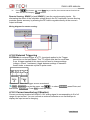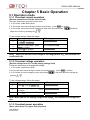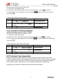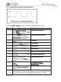
1
IT8500 USER MANUAL User’s Manual DC Programmable Electronic Load Model IT8500plus series IT8511+/IT8512+/IT8512B+/IT8512C+ /IT8513C+/IT8514B+/IT8514C+/IT8516C+ © Copyright 2010 All Right Reserved Ver1.1 /MAR, 2013/ IT8500+ 1 User Manual IT8500 USER MANUAL CHAPTER1 INSPECTION AND INSTALLATION ......................................................................................... 7 1.1 INSPECTION ........................................................................................................................................... 7 1.2 CLEANING ............................................................................................................................................. 7 1.3 INSTALLATION ........................................................................................................................................ 7 1.3.1 Mounting Dimensions .................................................................................................................. 7 1.3.2 Adjustment of handle ................................................................................................................. 11 1.3.3 Rack mounting ........................................................................................................................... 12 1.4 INPUT CONNECTIONS ............................................................................................................................ 14 CHAPTER2 QUICK STARTS ...................................................................................................................... 15 2.1 POWER-ON SELFTEST .......................................................................................................................... 15 2.1.1 Introduction ................................................................................................................................ 15 2.1.2 Selftest steps ............................................................................................................................. 15 2.1.3 Instrument won't turn on ............................................................................................................ 15 2.2 FRONT PANNEL INTRODUCTION ............................................................................................................. 17 2.3 REAR PANNEL INTRODUCTION .............................................................................................................. 18 2.4 VFD DISPLAY ANNUNCIATORS .............................................................................................................. 19 2.5 FRONT PANEL KEYS ............................................................................................................................. 19 2.6 COMBINATION KEYS ............................................................................................................................. 20 CHAPTER3 SPECIFICATIONS .................................................................................................................. 21 3.1 SPECIFICATIONS .................................................................................................................................. 21 3.2 SUPPLEMENTARY CHARACTERISTICS .................................................................................................... 25 CHAPTER4 FUNCTIONS AND CHARACTERISTICS................................................................................ 26 4.1 LOCAL MODE/REMOTE MODE ................................................................................................................ 26 4.2 OPERATION MODE ............................................................................................................................... 26 4.2.1 Constant current mode(CC) ....................................................................................................... 26 4.2.2 Constant voltage mode(CV) ...................................................................................................... 27 4.2.3 Constant resistance mode(CR) ................................................................................................. 27 4.2.4 Constant power mode(CW) ....................................................................................................... 27 4.3 INPUT ON/OFF CONTROL ....................................................................................................................... 28 4.3.1 On/Off operation ........................................................................................................................ 28 4.3.2 Short........................................................................................................................................... 28 4.4 SYSTEM MENU (SYSTEM) ..................................................................................................................... 28 4.5 CONFIG MENU (CONFIG)....................................................................................................................... 29 4.6 TRIGGER FUNCTION ............................................................................................................................. 30 4.6.1 Trigger operation........................................................................................................................ 30 4.6.2 Trigger source ............................................................................................................................ 31 4.7 TRANSIENT FUNCTION .......................................................................................................................... 31 4.7.1 Continuous mode ....................................................................................................................... 31 4.7.2 Pulse mode ................................................................................................................................ 31 4.7.3 Toggled mode ............................................................................................................................ 32 4.8 LIST OPERATION ................................................................................................................................. 32 4.9 SAVING AND RECALLING SETTINGS ........................................................................................................ 32 4.10 VON FUNCTION ................................................................................................................................. 33 4.11 OCP OPERATION ............................................................................................................................... 35 4.12 OPP OPERATION ............................................................................................................................... 36 4.13 BATTERY TEST ................................................................................................................................... 36 4.14 PROTECTION FEATURES ..................................................................................................................... 39 4.14.1 Over Voltage Protection (OVP)................................................................................................ 39 4.14.2 Over Current Protection (OCP) ................................................................................................ 39 4.14.3 Over Power Protection (OPP) .................................................................................................. 39 4.14.4 Over Temperature Protection (OTP) ....................................................................................... 40 4.14.5 Reverse voltage protection (LRV)............................................................................................ 40 4.15 KEY LOCK FUNCTION ......................................................................................................................... 40 4.16 THE TERMINALS ON THE REAR PANEL .................................................................................................. 40 4.16.1 Remote sensing ....................................................................................................................... 40 User Manual 2 IT8500 USER MANUAL 4.16.2 External Triggering................................................................................................................... 41 4.16.3 Current monitoring (I Monitor).................................................................................................. 41 CHAPTER 5 BASIC OPERATION .............................................................................................................. 42 5.1 OPERATION MODE ................................................................................................................................ 42 5.1.1 Constant current operation ........................................................................................................ 42 5.1.2 Constant voltage operation ........................................................................................................ 42 5.1.3 Constant power operation .......................................................................................................... 42 5.1.4 Constant resistance operation ................................................................................................... 43 5.2 TRANSIENT TEST OPERATION ................................................................................................................ 43 5.2.1 Continuous transient operation .................................................................................................. 44 5.2.2 Pulse transient operation ........................................................................................................... 45 5.2.3 Toggle transient operation ......................................................................................................... 46 5.3 LIST OPERATION .................................................................................................................................. 46 5.4 TEST FILES .......................................................................................................................................... 48 CHAPTER6 COMMUNICATION INTERFACES ......................................................................................... 53 6.1COMMUNICATION MODULES INTRUDUCTION ............................................................................................ 53 6.2 COMMUNICATION WITH PC ................................................................................................................... 54 3 User Manual IT8500 USER MANUAL Warranty Information Certification We certify that this product met its published specifications at time of shipment from the factory. Warranty This hardware product is warranted against defects in material and workmanship for a period of ONE year from date of delivery. During the warranty period our company will either repair or replace products which prove to be defective. Our company does not warranty that the operation for the software firmware or hardware shall be uninterrupted or error free. For warranty service, with the exception of warranty options, this product must be returned to a service facility designated by our company. Customer shall prepay shipping charges (and shall pay all duty and taxes) for products returned to our place for warranty service. Our company shall pay for return of products to Customer. Limitation of Warranty The foregoing warranty shall not apply to defects resulting from improper or inadequate maintenance by the Customer, Customer-supplied software or interfacing, unauthorized modification or misuse, operation outside of the environmental specifications for the product, or improper site preparation and maintenance. Assistance The above statements apply only to the standard product warranty. Warranty options product maintenance agreements and customer assistance agreements are also available. Safety Summary The following general safety precautions must be observed during all phases of operation of this instrument. Failure to comply with these precautions or with specific warnings elsewhere in this manual violates safety standards of design, manufacture, and intended use of the instrument .We assumes no liability for the customer’s failure to comply with these requirements. Environmental Conditions This instrument is intended for indoor use in a pollution degree 2 environment. It is designed to operate at a maximum relative humidity of 80%. Refer to the specifications tables for the AC mains voltage requirements and ambient operating temperature range. Before Applying Power Verify that all safety precautions are taken. Note the instrument's external markings described under "Safety Symbols". Ground the Instrument This product is a Safety Class 1 instrument (provided with a protective earth terminal). To minimize shock hazard, the instrument chassis and cover must be connected to an User Manual 4 IT8500 USER MANUAL electrical ground. The instrument must be connected to the AC power through a grounded power cable, with the ground wire firmly connected to an electrical ground (safety ground) at the power outlet. Note: Any interruption of the protective (grounding) conductor or disconnection of the protective earth terminal will cause a potential shock hazard that could result in personal injury. DO NOT OPERATE IN AN EXPLOSIVE ATMOSPHERE Do not operate the instrument in the presence of fumes or flammable gases. KEEP AWAY FROM LIVE CIRCUITS Operating person must not remove instrument covers except as instructed in this Guide for installing or removing electronic load modules. Component replacement and internal adjustments must be made only by qualified service personnel. Do not replace components with the power cable connected. Under certain conditions dangerous voltages may exist even with the power cable removed. To avoid injuries always disconnect power, discharge circuits and capacitors, and remove external voltage sources before touching components. DO NOT SERVICE OR ADJUST ALONE Do not try to perform internal service or adjustment unless another person capable of rendering first aid resuscitation is present. Safety Symbols Direct current Alternating current Both direct and alternating current Protective earth (ground) terminal Caution (refer to accompanying documents) WARNING The WARNING sign denotes a hazard. It calls attention to a procedure, practice, or the like, which, if not correctly performed or adhered to, could result in personal injury. Do not proceed beyond a WARNING sign until the indicated conditions are fully understood and met. CAUTION The CAUTION sign denotes a hazard. It calls attention to an operating procedure, or the like, which, if not correctly performed or adhered to, could result in damage to or destruction of part or all of the product. Do not proceed beyond a CAUTION sign until the indicated conditions are fully understood and met. NOTE We suggest you operate the instrucment after half an hour warm machine operation to ensure the accuracy. The content of this manual is subject to change without notice. 5 User Manual IT8500 USER MANUAL Introduction IT8500plus series DC electronic loads are single channel programmable electronic load which can provide multiple solutions according to the requirements of your design and test. This series have international advanced functions and features. • Highlight VFD display • Dynamic mode: Up to 10KHZ; • Measurement resolution: 0.1mV,0.1mA • Measurement speed: up to 40KHZ • Four operation mode:CV(Constant Voltage),CC,CR,CW • Rotary knob, making the operation more convenient • Remote Sense function • Battery test function • Memory capacity to save/recall setting parameters: 100 registers • Short circuit function • Intelligent fans • Build-in Buzzer as alarm signal • Power off memory function Operational accessory: IT8511+/IT8512+/IT8512B+/IT8512C+/ IT8513C+ optional accessory: IT-E121(RS232),IT-E122(USB),IT-E123(RS485) IT-E151(Rack mount kit) IT8514B+/IT8514C+/IT8516C+ optional accessory: No, the models equipped with RS232/USB interface. Model Voltage Current Power IT8511+ IT8512+ IT8512B+ IT8512C+ IT8513C+ IT8514B+ IT8514C+ IT8516C+ 120V 120V 500V 120V 120V 500V 120V 120V 150W 300W 300W 300W 600W 1500W 1500W 3000W User Manual 30A 30A 15A 60A 120A 60A 240A 240A Communication interface COM COM COM COM COM USB/RS232 USB/RS232 USB/RS232 6 IT8500 USER MANUAL Chapter1 Inspection and Installation 1.1 Inspection Make sure that you have received the following compontents in the table below (one instrucment for example).If anything has been lost, please contact with your franchiser. Item One power cord Part Number IT-E171 IT-E172 IT-E173 IT-E174 One user’s manual One test report Description You can choose different power cord according to your region. Installation,operation,self-test information Calibration report 1.2 Cleaning Do not clean any internal parts of the electronic loads casually.If you need to clean the outside cover, please use a dry cloth or moistish cloth to wipe. Caution: Cut the power off before cleaning. 1.3 Installation The following outside drawing has marked the dimension information.The instrucment should be fixed in a ventilation and reasonable size of space. 1.3.1 Mounting Dimensions IT8511+/IT8512+/IT8512B+/IT8512C+ Dimension: 214.5 mmW x 88.2mm H x 354.6mm D Refer to the following dimension drawing: 7 User Manual IT8500 USER MANUAL unit:minimeter(mm) IT8513C+ Dimension: 214.5 mmW x 88.2mm H x 453.5mm D unit:minimeter(mm) IT8514B+/IT8514C+ Dimension: 436.5 mmW x 88.2mm H x 463.5mm D User Manual 8 IT8500 USER MANUAL unit:minimeter(mm) IT8516C+ Dimension: 482.5 mmW x 174.5mm H x 531.5mm D 9 User Manual IT8500 USER MANUAL User Manual 10 IT8500 USER MANUAL unit:minimeter(mm) 1.3.2 Adjustment of handle Model IT8511+/IT8512+/IT8512B+/IT8512C+/IT8513C+ has handle. The following pictures demonstrate various ways to use the handle. Please use proper strength to adjust the handle to enable it in a favorable location. 11 User Manual IT8500 USER MANUAL The handle may be removed if desired. The way to remove the handle: Move the handle to depart it from the load’s side by 2mm and then rotate the handle to the position as below pictures, remove it. 1.3.3 Rack mounting Model IT8511+/IT8512+/IT8512B+/IT8512C+/IT8513C+can be mounted into a standard 19-inch rack. Rack mount kits are available as Option IT-E151. The electronic load can be mounted in a standard 19-inch rack panel or enclosures using an Option IT-E15C1 rack mount kit. A rack mount kit for joining two half-rack units is also available by using Option IT-E151. Before you install IT-E151, you should first remove the handle as described in 1.3.2 Then tear the tags on both sides. User Manual 12 IT8500 USER MANUAL Rack Installation: Elevation for Installation one electronic load in a standard 19-inch rack Side elevation for Installation one electronic load in a standard 19-inch rack Elevation for Installation two electronic loads in a standard 19-inch rack Caution: Be careful not to grip your fingers due to too much strength when you take off the handle. 13 User Manual IT8500 USER MANUAL 1.4 Input connections Power Cord Connect the power cord to the IEC 320 connector on the rear of the unit. If the wrong power cord was shipped with your unit, contact your nearest Agent to obtain the correct cord. See the following figure for the part number and ordering options. E N E E L China IT-E171 User Manual L E N N United States/Canada L Europe IT-E172 IT-E173 14 L N United Kingdom IT-E174 IT8500 USER MANUAL Chapter2 Quick Starts 2.1 Power-on selftest 2.1.1 Introduction A successful test process indicates that the instrucment meets the factory specifications and can be operated well. 2.1.2 Selftest steps Power cord should be connected correctly.Following is the detailed selftest steps. Procedure VFD display About 1S later System Selftest…. About 1S later 0.0000V 0.00W 0.0000A CC=0.000A OFF CC Press (Shift)+7 Auto IT85XX Ver—1.XX SN1:XXXXXXXXXXXXX SN2: XXXXX Explanations System self check VFD: The first line display actual voltage and current value The second line display the actual power value and the setting current/voltage/power/resistance value The third line display the input state/operation mode Display products information.You can press direction buttons to examine product’s model/SN/software version It may display following prompts when selftest fail. 1. “Eeprom Fail” means EEPROM is not functional. 2. “Eeprom data lost” means parameters of power-on have been lost.Reset them by pressing (Shift)+4(save)+0 3. “Cal data lost” means calibration date have been lost. 4. “Eeprom Data lost”means the system settings are lost, reset them in system menu. If you experience these error messages, the instrument should be returned to ITECH for service. WARNING:The electronic load is shipped from factory with a power cord that has a plug appropriate for your location. Your electronic load is equipped with 3-wire grounding type power cord; the third conductor being ground. The electronic load is grounded only when the power-line cord is plugged into an appropriate receptacle. Do not operate your power supply without adequate cabinet ground connection. 2.1.3 Instrument won’t turn on If the instrument won’t turn on, please check as follows. 1) Check whether the power cord is connected well. 15 User Manual IT8500 USER MANUAL Please ensure the power cord is plugged into the back of the instrument, the other end of the cord is plugged into a live AC power outlet and the power is on. 2) Check the power-line voltage setting. The line voltage is set to the proper value for your country(110VAC or 220VAC) when the electronic load is shipped from facory. Change the line voltage setting if it’s not correct. 3) Check whether the fuse is ok. If the instrument still won’t turn on, remove the power cord from the instrument. Open the fuse container on the rear panel and check the fuse for continuity.Please refer 4) to take down the fuse. If the fuse is an open circuit, replace it with the proper fuse indicated in the following table. Model IT8511+ IT8512+ IT8512B+ IT8512C+ IT8513C+ IT8514B+ IT8514C+ IT8516C+ 4) Fuse specification for 220 V AC operation T0.5A 250V T0.5A 250V T0.5A 250V T0.5A 250V T1.25A 250V T1.25A 250V T1.25A 250V T2.5A 250V Fuse specification for 110 VAC operation T1.25A 250V T1.25A 250V T1.25A 250V T1.25A 250V T2.5A 250V T2.5A 250V T2.5A 250V T5A 250V The method of replacing fuse Use a flat-bladed screwdriver to open the small plastic cover under the AC input connector on the rear panel of the load , then you can see the fuse. Please use the matching fuse.(figure showing the fuse location) Fuse User Manual 16 IT8500 USER MANUAL 2.2 Front pannel introduction Front panle of IT8511+/IT8512+/IT8512B+/IT8512C+/IT8513C+ Front panel of IT8514B+/IT8514C+ Front panel of IT8516C+ 17 User Manual IT8500 USER MANUAL ① Power switch ② VFD display ③ Composite key and Local key ④ Number key: Set the parameters value Achieve the menu’s function by key combination ⑤ Function key: Set the operation mode Control the input state:On/Off ⑥ Direction function ⑦ Rotary knob ⑧ Input terminal 2.3 Rear Pannel Introduction Rear panel of IT8511+/IT8512+/IT8512B+/IT8512C+/IT8513C+ Rear panel of IT8514B+/IT8514C+ User Manual 18 IT8500 USER MANUAL Rear panel of IT8516C+ Fan ① ② ③ ④ ⑤ Power swith (110V/220V) Power input socket I-monitor DB9 COM interface/RS232 interface(IT8514B+/IT8514C+/IT8516C+) ⑥ Remote measurement and external trigger terminals ⑦ USB interface 2.4 VFD Display annunciators OFF CC CV CR The load is off. Constant current mode Constant voltage mode Constant resistance mode Error Trig Sense Prot CW Constant power mode Auto Rmt Timer An error has occurred. Waiting for the trigger signal Remote sensing is on. OCP function is on. Voltage range automatically seleted function is open Instrument is in the remote Lock state. LOAN ON is on. Shift The keyboard is locked. Shift button has been pressed. 2.5 Front panel keys ( Blue-green) (Gray) Shift button is a composite key. Local button is used to switch local and remote mode. 19 User Manual IT8500 USER MANUAL 0 (Gray-white) Power on button ~ 9 Enter the digits 0 to 9. Decimal point The escape key ESC Choose constant current mode. Choose constant voltage mode. Choose constant resistance mode. Choose constant power mode. Enter the selected value or setting. Turns DC Load ON or OFF (OFF is high impedance state). Scroll up key Scroll down key Scroll left and right key 2.6 Combination keys Press (Shift) button first and then other keys to achieve all kinds functions in the following table. Turn short circuit on or off. +1(Short) +2(Tran) +3(List) Start or stop transient condition. Set LIST operation parameters. +5(Battery) Store the DC Load state in non-volatile memory. Turn on or off battery testing function. +6(Prog) Enter auto tese function. +7(Info) Display product’s Model/SN/Version. +8(System) System menu setting +9(Config) Configure menu setting +0(Pause) Press this button if you need a pause when runing an auto test file. Cause an immediate trigger. +4(Save) + (Trigger) +CC(OCP) Enter OCP test function. +CV(Setup) Set detailed parameters in CC/CV/CW/CRmode. +CW(OPP) Enter OPP test function. +Enter(Recall) Recall the DC Load state from non-volatile memory. +On/Off(Lock) Key lock function User Manual 20 IT8500 USER MANUAL Chapter3 Specifications 3.1 Specifications Model IT8511+ Input voltage Input current Rated value Input power ( 0~40 ℃) Minimum operation voltage range CV mode resolution CW mode 0~120V 0~30A 0~3A 0~30A 150 W 300W 0.14V at 3A 1.4V at 30A 0.12V at 3A 1.2V at 30A 0~18V 0~120V 0~18V 0~120V resolution accuracy ±(0.05%+0.05%FS) range CR mode 0~120V 0~3A 10mV 1mV 10mV ±(0.05%+0.025% ±(0.05%+0.02%FS ±(0.05%+0.02%FS) ±(0.05%+0.025%FS) FS) ) 0~30A 0~3A 0~30A 0~3A 1mA 0.1mA 1mA 0.1mA accuracy CC mode IT8512+ range resolution accuracy range resolution accuracy 1mV ±(0.05%+0.05%F ±(0.05%+0.05%FS ±(0.05%+0.05%FS) S) ) 0.05Ω~10Ω 10Ω~7.5KΩ 0.05Ω~10Ω 10Ω~7.5KΩ 16bit 16bit 0.01%+0.0008S 0.01%+0.08S 0.01%+0.0008S 0.01%+0.08S 150W 300W 10mW 10mW 0.1%+0.1%FS 0.1%+0.1%FS Dynamic mode Dynamic mode T1&T2 accuracy Rising/ decending slope CC mode 50uS~3600S /Res:1 uS 1uS+100ppm 0.0001~0.3A/uS 0.001~1.5A/uS CC mode 50uS~3600S /Res:1 uS 1uS+100ppm 0.0001~0.3A/uS 0.001~1.5A/uS 0~18V 0~120V Measuring range range Readback voltage Readback current Readback power resolution accuracy range 0~18V 0~120V 0.1mV 1mV 0.1mV 1mV ±(0.025%+0.025%FS ±(0.025%+0.025 ±(0.025%+0.025% ±(0.025%+0.025%FS ) %FS) FS) ) 0~3A 0~30A 0~3A 0~30A resolution 0.1mA 1mA 0.1mA 1mA accuracy ±(0.05%+0.05%FS) ±(0.05%+0.05%FS) range 150W 300W resolution 10mW 10mW accuracy ±(0.1%+0.1%FS) ±(0.1%+0.1%FS) Protection range OPP OCP ≒160W ≒320W ≒3.3A ≒33A ≒3.3A ≒33A OVP ≒125V ≒125V OTP ≒85℃ ≒85℃ Specification 21 User Manual IT8500 USER MANUAL Short current(CC) ≒3.3/3A ≒33/30A ≒3.3/3A ≒33/30A voltage(CV) resistance(CR ) 0V 0V 0V 0V ≒45mΩ ≒45mΩ ≒40mΩ ≒40mΩ Input impendance Dimension 150KΩ 150KΩ 214.5mm*88.2mm*354.6mm 214.5mm*88.2mm*354.6mm Model IT8512B+ Input voltage Input current Rated value Input power ( 0~40 ℃) Minimum operation voltage range 0~500V CV mode resolution CW mode 0~3A 0~30A 0~6A 060A 300W 300W 0.6V at 3A 3V at 15A 0.25V at 6A 2.5V at 60A 0~50V 0~500V 0~18V 0~120V resolution accuracy ±(0.05%+0.05%FS) range CR mode 0~120V 10mV 1mV 10mV ±(0.05%+0.025% ±(0.05%+0.02%FS ±(0.05%+0.02%FS) ±(0.05%+0.025%FS) FS) ) 0~60A 0~3A 0~15A 0~6A 1mA 0.1mA 1mA 0.1mA accuracy CC mode IT8512C+ range resolution accuracy range resolution accuracy 1mV ±(0.05%+0.05%F ±(0.05%+0.05%FS ±(0.05%+0.05%FS) S) ) 0.3Ω~10Ω 10Ω~7.5KΩ 0.3Ω~10Ω 10Ω~7.5KΩ 16bit 16bit 0.01%+0.0008S 0.01%+0.08S 0.01%+0.0008S 0.01%+0.08S 300W 300W 10mW 10mW 0.1%+0.1%FS 0.1%+0.1%FS Dynamic mode Dynamic mode T1&T2 accuracy Rising/ decending slope CC mode 50uS~3600S /Res:1 uS 5uS+100ppm 0.0001~0.3A/uS 0.001~0.8A/uS CC mode 50uS~3600S /Res:1 uS 5uS+100ppm 0.0001~0.3A/uS 0.001~1.2A/uS 0~18V 0~120V Measuring range range Readback voltage Readback current Readback power resolution accuracy range resolution 0~50V 0~500V 1mV 10mV 1mV 10mV ±(0.025%+0.025%FS ±(0.025%+0.025 ±(0.025%+0.025% ±(0.025%+0.025%FS ) %FS) FS) ) 0~3A 0~15A 0~6A 0~60A 0.1mA 1mA 0.1mA 1mA accuracy ±(0.05%+0.05%FS) ±(0.05%+0.05%FS) range 300W 300W resolution 10mW 10mW accuracy ±(0.1%+0.1%FS) ±(0.1%+0.1%FS) Protection range OPP User Manual ≒320W ≒320W 22 IT8500 USER MANUAL OCP ≒3.3A ≒16A ≒6.5A ≒65A OVP ≒530V ≒125V OTP ≒85℃ ≒85℃ Specification Short current(CC) ≒3.3/3A ≒16/15A ≒6.5/6A ≒65/60A voltage(CV) resistance(CR ) 0V 0V 0V 0V ≒180mΩ ≒180mΩ ≒40mΩ ≒40mΩ Input impendance Dimension 150KΩ 150KΩ 214.5mm*88.2mm*354.6mm 214.5mm*88.2mm*354.6mm Model Rated value ( 0~40 ℃) CV mode CC mode CR mode CW mode IT8513C+ IT8514C+ Input voltage 0~120V 0~120V Input current 0~12A 0~120A 0~24A 0~240A 1500W Input power 600 W Minimum operation 0.2V at 12A 2V at 120A 0.25V at 24A 2.5V at 240A voltage range 0~18V 0~120V 0~18V 0~120V resolution 1mV 10mV 1mV 10mV ±(0.05%+0.02%FS) ±(0.05%+0.025%FS) ±(0.05%+0.02%FS) ±(0.05%+0.025%FS) accuracy range 0~12A 0~120A 0~24A 0~240A resolution 1mA 10mA 1mA 10mA accuracy range resolution accuracy range resolution accuracy ±(0.05%+0.05%FS) 0.05Ω~10Ω 10Ω~7.5KΩ 16bit 0.01%+0.08S *2 0.01%+0.0008S 600W 10mW ±(0.2%+0.2%FS) ±(0.1%+0.1%FS) 0.05Ω~10Ω 10Ω~7.5KΩ 16bit 0.02%+0.08S *2 0.02%+0.0008S 1500W 10mW ±(0.2%+0.2%FS) Dynamic mode T1&T2 accuracy Rising/ decending slope T1&T2 CC mode 100uS~3600S /Res:1 uS 10uS±100ppm 100uS~3600S /Res:1 uS 10uS±100ppm 0.001~0.2A/uS 0.01~1.6A/uS 0.001~0.3A/uS 0.01~3.2A/uS ≒60uS ≒60uS ≒60uS ≒60uS Measuring range Readback voltage Readback current Readback power range resolution accuracy range resolution accuracy range resolution 0~18V 0.1 mV 0~120V 0~18V 0~120V 1mV 0.1 mV 1mV ±(0.025%+0.025%FS) 0~12A 0~120A 0~24A 0~240A 1mA 10mA 1mA 10mA ±(0.05%+0.05%FS) ±(0.05%+0.05%FS) 600W 1500W 10mW 10mW accuracy ±(0.2%+0.2%FS) ±(0.2%+0.2%FS) Protection range OPP OCP ≒1550W ≒620W ≒13A ≒130A 23 ≒26.7A ≒267A User Manual IT8500 USER MANUAL OVP OTP ≒125V ≒95℃ current(CC) voltage(CV) resistance(CR ) Short Input impendance Dimension CV mode CC mode CR mode CW mode Specification ≒130/120A 0V ≒13/12A 0V ≒15mΩ ≒15mΩ ≒26.7/24A 0V ≒267/240A 0V ≒8mΩ ≒8mΩ 150KΩ 150KΩ 214.5mm*88.2mm*453.5mm 436.5mm*88.2mm*463.5mm Model Rated value ( 0~40 ℃) ≒125V ≒85℃ IT8514B+ IT8516C+ Input voltage 0~500V 0~120V Input current 0~6A 0~60A 0~24A 0~240A Input power 1500 W 3000W Minimum operation 0.25V at 6A 2.5V at 60A 0.15V at 24A 1.5V at 240A voltage range 0~50V 0~500V 0~18V 0~120V resolution 1mV 10mV 1mV 10mV ±(0.05%+0.02%FS) ±(0.05%+0.025%FS) ±(0.05%+0.02%FS) ±(0.05%+0.025%FS) accuracy range 0~6A 0~60A 0~24A 0~240A resolution 1mA 10mA 1mA 10mA accuracy range resolution accuracy range resolution accuracy ±(0.05%+0.05%FS) 0.05Ω~10Ω 10Ω~7.5KΩ 16bit 0.02%+0.08S *2 0.02%+0.0008S 1500W 10mW ±(0.2%+0.2%FS) ±(0.1%+0.1%FS) 0.05Ω~10Ω 10Ω~7.5KΩ 16bit 0.02%+0.08S *2 0.02%+0.0008S 3000W 10mW ±(0.2%+0.2%FS) Dynamic mode T1&T2 accuracy Rising/ decending slope CC mode 100uS~3600S /Res:1 uS 10uS±100ppm 120uS~3600S /Res:1 uS 10uS±100ppm 0.001~0.15A/uS 0.01~0.8A/uS 0.001~0.3A/uS 0.01~2.8A/uS ≒60uS ≒60uS ≒70uS ≒70uS T1&T2 Measuring range Readback voltage Readback current Readback power range resolution accuracy range resolution accuracy range resolution accuracy 0~50V 0.1 mV 0~500V 0~18V 0~120V 1mV 0.1 mV 1mV ±(0.025%+0.025%FS) 0~6A 0~60A 0~24A 0~240A 1mA 10mA 1mA 10mA ±(0.05%+0.05%FS) ±(0.1%+0.1%FS) 1500W 3000W 10mW 10mW ±(0.2%+0.2%FS) ±(0.2%+0.2%FS) Protection range OCP OVP User Manual ؒ3050W ؒ1550W OPP ≒67A ≒6.7A ≒530V ≒260A ≒26A ≒125V 24 IT8500 USER MANUAL ≒85℃ OTP Short current(CC) voltage(CV) resistance(CR ) Input impendance Dimension ≒85℃ ≒6.7/6A 0V Specification ≒67/60A 0V ≒30mΩ ≒30mΩ ≒26/24A 0V ≒260/240A 0V ≒5mΩ ≒5mΩ 150KΩ 150KΩ 436.5mm*88.2mm*463.5mm 436.5mm*176mm*463.5mm 3.2 Supplementary characteristics Memory capacity:100 registeres Suggested calibration frequency:Once a year AC input level(A transfer switch is selectable on the rear panel) Option Opt.1: 220V ±10% 50Hz/60Hz Option Opt.2: 110V ±10% 50Hz/60Hz Cooling type Intelligent fans Fans working principle: Fans running speed is determined by radiator temperature.When temperature reaches 40℃,fans start to work and intelligently adjust its speed with temperature variation. Operation temperature 0 to 40 °C Storage temperature -20 to 70 °C Using condition Suitable for indoor use.Allowable maximum humidity is 80%, without condensation. 25 User Manual IT8500 USER MANUAL Chapter4 Functions and Characteristics This chapter elaborates on the functions and characteristics of electronic loads.Contents following sections: Local mode/Remote mode Operation mode(CC/CV/CR/CW) On/Off control Four trigger function Transient mode List mode Save/Recall VON function OCP test OPP test Battery test funtion Full protection function,OCP,OVP,OTP,OPP,Reverse voltage Safe-lock function Terminals function at the rear panel 4.1 Local mode/Remote mode There are two types of control modes for IT8500+ series products:Local mode and Remote mode. In remote mode, you can operate the electronic loads through PC via communication cable(optional). While After power on electronic loads, it defaults in local mode and all buttons are avaiable in this mode.In remote control mode, the keys on the front pannel can not work except local key.Customers could through Local key to switch the control mode. 4.2 Operation Mode There are four operation modes of IT8500+ series products: 1: Constant current mode (CC) 2: Constant voltage mode (CV) 3: Constant resistance mode (CR) 4: Constant power mode(CW) 4.2.1 Constant current mode (CC) In constant current mode, the DC load will comsume a constant current, regardless of the voltage at its terminals. I Setting current Load current Input voltage V CC mode Diagram 4-1 I-V curve in CC mode User Manual 26 IT8500 USER MANUAL 4.2.2 Constant voltage mode (CV) In constant voltage mode, the DC load will cause a constant voltage to appear at its terminals. V Setting voltage Input voltage Input current I CV mode Diagram 4-2 I-V curve in CV mode 4.2.3 Constant resistance mode (CR) In constant resistance mode, the DC load will behave as a fixed resistance value.As shown below,the load linearly changes the current value with the rising of input voltage. I Slope is equal To the setting resistance Load current Input voltage V CR mode Diagram 4-3 I-V curve in CR mode 4.2.4 Constant power mode (CW) In constant power mode,the DC load will cause a constant power to be dissipated in the load.As shown below,the load current is decreasing with the rising of input voltage,while power always maintain the setting value. Diagram 4-4 I-V curve in CP mode 27 User Manual IT8500 USER MANUAL 4.3 Input On/Off control 4.3.1 On/Off operation On/Off button on the front panel is used to manually toggle the instrument between its set mode and an infinite impedance state, i.e control input on and off. On/Off button lighted indicates the load input is on, meanwhile the OFF indicator will disappear. 4.3.2 Short Short circuit simulation and short circuit current measuremen:you may press (Shift)+ 1(short) botton to emulate a short state.It can be used to check whether the tested instrument’s short protection is avaiable. In short mode,the DC load will draw maximum current from the DC supply in any of the four operation modes(CC,CV,CW or CR).In CC,CV,or CR mode,you may press (Shift)+1(short) to stop short.The DC load will return to its previous operation.However,in CW mode,the short current will continue to be drawn.To stop the short,you must press the On/Off key after you press (Shift)+1(short). When emulating a Short in CC, CW or CR mode, the maximum allowable short current is equal to the 110% of current range. 4.4 System menu (System) Press (Shift)+ 8(System)to enter the system menu. POWER-ON Power on state of instrument RST(default) Do not remember state in SAVE 0.Customer can save a often used data in SAVE 0 to recall POWER-ON when power on the DC load next time. SAV0 Remember state in SAVE 0 BUZZER BUZZER ON(default) OFF KNOB UPDATE(default) KNOB OLD SOURCE MANUAL(Def) TRIGGER EXTERNAL BUS User Manual Enable audible beep when key is pressed No sound when key is pressed The value modified with knob during operation will be saved after load is off.For example; the DC load is set to 1A by press CC and turned on the input.Then increase the setting value to 2A with knob.When customer turn off load and trun on again, the setting value changes to 2A. As explained above, after the DC load is turned on again,the setting value is 1A instead of 2A changed with knob. Set trigger mode Triggered from the (Shift)+ (Trigger) key Triggered from a TTL high signal at the trigger connector on rear panel Triggered from a serial bus command 5AH 28 IT8500 USER MANUAL MEMORY HOLD MEMORY GROUP= 0 DISP-TIMER DISPLAY RS-232 ON OFF(default) RS-232 4800_8N 1 9600_8N 1 19200_8N 1 38400_8N 1 ADDRESS RUNMODE DEFAULT ADDRESS= 0 RUN NORMAL BATTERY PROG_TEST OCP_TEST OPP_TEST DEFAULT NO YES Receving a command 9DH Recall the prestored datas 0:indicates1-10 group;1:indicates 11-20group, by parity of reasoning Timer function Enable timer function Disable timer function Baudrate 4800, data bit 8, none parity, stop bit 1 Baudrate 9600, data bit 8, none parity, stop bit 1 Baudrate 19200, data bit 8, none parity, stop bit 1 Baudrate 38400, data bit 8, none parity, stop bit 1 Set the instrument’s address(0~31) Runing mode at power on Normal mode Default in battery test mode at power on Default in autotest mode at power on Default in OCP test mode at power on Default in OPP test mode at power on Do not return instrument to factory default settings. Retrun instrument to factory default settings 4.5 Config menu (Config) Press (Shift)+9(Config) to enter the menus. Max-P MAX POWER=150.00W Set hardware power protection Set hardware OPP value Set software current protecting state A-LIMIT A-LIMIT PROTECT ON A-LIM POIN=30.000A A-LIM DELAY=3S OFF P- LIMIT P-LIM POIN=150.00W Enable software over current protection function Set the software OCP level Set the OCP delay time Disable the software OCP funtion Set software power protecting state. Set the software OPP level. 29 User Manual IT8500 USER MANUAL P-LIM DELAY=3S Set the OPP delay time. TIMER Set load on timer LOAD-TIMER ON Enable load-on timer LOAD-TIMER=10.0S OFF Set the load on time(0.1S~9999.9S) Disable load on timer V-RANGE V-RANGE ON OFF Voltage auto-rangefuntion Enable voltage auto range function Disable voltage auto range function FILTER MEASURE FILTER COUNT = 2^14 TIME-V1 TIME-VOLT1=0.000V Set the filter parameter Filter count set, range 2~16 Set the start time, to measure the voltage rise/fall time. TIME-V2 TIME-VOLT2=120.00V Set the end time, to measure the voltage rise/fall time CR-LED CR-LED ON OFF Imitate LED (in CR mode) Open the function(in CR mode,press shift+CV to set Vd value) Disenable the function REM- SENSE SENSE ON OFF Remote sense function Enable remote sense function Disable remote sense function VON VON RESET Set the load’s VON point LIVING VON POINT = 0.10V LATCH VON point living state Set the VON value VON point latch state, ON /OFF VON POINT = 0.10V Set the VON value RESET NO YES Reset the config menu Do not reset Reset 4.6 Trigger function 4.6.1 Trigger operation Triggering is used with the transient operation; list operation and test function.There are four types of triggers you can use for IT8500+ products. User Manual 30 IT8500 USER MANUAL 4.6.2 Trigger source Manual: An immediate trigger is created by pressing (Shift)+ (Trigger) on the front panel. External(TTL signal): An external trigger is a TTL low signal applied to the trigger connection on the rear panel.This TTl signal must last for more than 10us. Bus: The instrument will be triggered if command 5AH is sent via the communication interface. Hold: The instrument will be triggered if command 9DH is sent via the communication interface. 4.7 Transient function The transient test allows switching between two different load values.A common application is to test the dynamic characteristics of DC source. There are three different types of transient operation: continuous, pulse, toggled. 4.7.1 Continuous mode In continuous transient operation, the load iscontinuously switched between two load values.An example is shown in the following figure: 4.7.2 Pulse mode In pulse operatrion,the load operates at the A value that has been entered until a trigger is received.At the trigger,the load switches to the B value and stays at that level for the B timing value.Then the load switches back to the A value and stays there until another trigger is received. 31 User Manual IT8500 USER MANUAL 4.7.3 Toggled mode In toggled transient operation,the load starts at the stored parameters for the mode.When a trigger is received,the load switches to B value.When another trigger is received,the load switches to the A level.It stays at the A value until another trigger is received,at which point it switches to the B value.Here’s an example: 10A 5A TRG TRG Toggled Transient Operation 4.8 LIST operation List mode allows you to generate a complex current sequence. Moreover, the mode change can be synchronized with an internal or external signal, to accomplish dynamic and precise test A list file includes following parameters: file name, step counts (range 2-84), time width of single step(0.00005s~3600s),step value and slope.The edited list file can be saved in nonvolatile memory, can be recalled easily.The DC load provides 7 nonvolatile registers to save list files for recall later. In list mode,the DC load start to run the list file once receiving a trigger signal, continue to run once receiving another trigger signal.To illustrate the use of a list,we’ll create a list that runs the following constant current profile on a power supply: Trigger 0 1 2 3 4 5 List count=1 List count=2 List sequence 4.9 Saving and recalling settings We can save some often-used parameters in the non volatile memory, including working mode, voltage/current value and so on.IT8500plus series provide 100 non-volatile registers. They are divided into 10 Memory groups: Group0-9.You can set it in the system menu.Group0 means you can save and recall parameters in 0-10 registers. Group1 User Manual 32 IT8500 USER MANUAL means you can save and recall parameters in 11-20 registers. Group2-Group9 can be concluded in the same manner. Save and Recall operation: For example: the instrucment works in CC mode, setting value is 1A, Memory Group is 6. Save “CC 1A” in the 61th register and then recall. Operation VFD Display SAVE 1. Set the parameters ok. To save the instrument's settings 5.8949V 0.99994A 5.89W SAVE 61 to a register, press (Shift)+4(Save). Enter number 6 and 1. 5.8949V 0.99994A 2、Then press Enter . The setting is saved. 5.89W cc=1.000A RECALL 1. To recall the instrument's settings from a register, press 5.8949V 0.99994A 5.89W cc=1.000A (Shift)+ Enter(Recall). 5.8949V 0.99994A 2、Enter 1.Then the setting is recalled. 5.89W cc=1.000A Note: Saving operation will overwrite any values previously saved in that register. Recalling operation will light the Enter . You should press ESC to escape the recalling state before setting other parameters. 4.10 VON function The DC load can be set to only turn on if the voltage is above a set value(VON set) under configure menu by pressing (Shift)+9.There are two types of VON function:Living and Latch.The following will have detailed description for the two types. Note: VON set is used to ensure an electronic system under test will not have power applied unless the supply voltage is above a certain value.If you have no such testing request, do not set this value arbitrarily.If your instrument can not work normally, for example, set CC=1A, after turn on the input while the current is still 0A instead of setting value 1A, then you should check VON set firstly.If VON set is not 0V, then please modify to 0V. 33 User Manual IT8500 USER MANUAL VON LIVING MODE In Living mode, when power is applied to the DC load, the voltage must rise above VON setting before the load draws current from the source.If the voltge below VON setting on the load’s terminals, the load will turn off input. VON LATCH MODE In Latch mode,as before,the load will turn on only when the voltage exceed VON setting,but once on,it will now stay on,even if the voltage drops to zero. User Manual 34 IT8500 USER MANUAL 4.11 OCP operation OCP test process: After input voltage reaches VON point,the DC load start to draw a current from the source after a delay time.The current value will increase by a certain step size at regular intervals.Simultaneously,the DC load will judge whether the input voltage is lower than OCP voltage you’ve set.If it is,then the present current value will be compared to see if it is in the current range you’ve set,in this range,the OCP test will Pass or fail.On the contrary,the DC load will continue to increase drawing current and compare the voltage. To start an OCP test,press (Shift)+ (Trigger). Press (Shift)+CC(OCP) to enter OCP operation. OCP TEST 1.VON LEVEL=0.000V Set Voltage threshold 2.VON DELAY=0.00S After delay certain time,the DC load starts to draw current. 3.RANGE=3.000A Set current range 4.START=0.1000A Set start current EDIT 5.STEP=0.1000A Set step current 6.STEP DEL=0.20S Set delay time of each step 7.END=2.0000A Set end current 8.OCP VOLT=2.000V Set OVP value 9.MAX TRIP =1.5000A Upper limit of OCP value 10.MIN TRIP=0.9000A Lower limit of OCP value SAVE OCP FILE=1 Save OCP test file (1-10) Set the power on mode to be OCP test mode: Operation Display on front pannel 0.0000V 0.000A POWER-ON BUZZER 1.Press (shift)+8(system) enter into sysmtem menu 2.Press right key,select RUNMODE and confirm with Enter button 3.Press direction key to select OCP_TEST,Press Enter to confirm. 0.0000V 0.000A RUN <NORMAL 0.0000V 0.000A RUN <OCP_TEST 4,Press Esc button to quit the set. After above steps,press 0.0000V STOP 0.000A 0.000A (Trigger) button to run ocp test file. Recall OCP file: Press shift+ Enter button to select programe file,the panel displays “CALL OCP FILE= 1.Enter the file name(1-10),press Enter button to confirm. According to the following steps to escape OCP mode:press (shift)+8(system)------“RUNMODE”-----“Enter”-------select “NORMAL”mode----“Enter”. 35 User Manual IT8500 USER MANUAL 4.12 OPP operation OPP test process:When the input voltage has reached VON point, power will begin to work after a delay time.The power value will increase by a step size at regular intervals.Simultaneously,the DC load will judge wether the input voltage is lower than OPP voltage(you need to set).If it is,then the present current value will be compared to see if it is in the current range you’ve set,in this range,the OPP test will Pass or fail.On the contrary,the power will continue to increase within the cut-off current range.And then compare OPP voltage with input voltage too. To start a OPP test, press (Shift)+ (Trigger). Press (Shift)+CW(OPP) to enter OPP test operation. OPP TEST RUN STOP Run OPP test file OPP TEST CALL Recall OPP File=1 Recall OPP test file(range file1-file10) OPP TEST 1.VON LEVEL=0.000V Set Voltage on value 2.VON DELAY=0.01S Set Voltage on delay time 3.RANGE=5A Set working current range OPP TEST 4.START =0.1W Set start power value 5.STEP =1W Set step power value EDIT 6.STEP DEL=1S Set step delay time 7.END =12W Set cut-off power value 8.OPP VOLT=7V Set OPP value 9.MAX TRIP =6.5W Upper limit of OPP value 10.MIN TRIP =5.6W Lower limit of OPP value SAVE OPP FILE=1 Save OPP test file Set the power on mode to be OPP test mode Operation Display on front pannel 0.0000V 0.000A POWER-ON BUZZER 1.Press (shift)+8(system) enter into sysmtem menu 2.Press right key,select RUNMODE and confirm with Enter button 3.Press direction key to select OCP_TEST,Press Enter to confirm. 0.0000V 0.000A RUN <NORMAL 0.0000V 0.000A RUN <OPP_TEST 4,Press Esc button to quit the set. After above steps,press 0.0000V STOP 0.000A 0.000A (Trigger) button to run OPP test file. Recall OPP file Press shift+ Enter button to select programe file,the panel displays “CALL OPP FILE= 1.Enter the file name(1-10),press Enter button to confirm. User Manual 36 IT8500 USER MANUAL According to the following steps to escape OPP mode:press (shift)+8(system)------“RUNMODE”-----“Enter”-------select “NORMAL”mode----“Enter”. 4.13 Battery test IT8500plus series products test the battery capability in CC/CW/CR mode. The test mode should be set first, and then the discharge stop conditions. There are three discharge stop conditions to be set for IT8500 plus series products. When user only need to do battery testing in one or two stop conditions, the other conditions should be set to the specified value (STOP VOLT:0V;STOP CAP:999.999AH;STOP TIMER:99999S). When the system checks the discharging time or battery voltage or capacity is equal to the setting stop value or under an insecurity state, the battery test will stop, and the E-Load will turn off. The battery voltage, discharge current, discharge time and discharged capability are displayed on the VFD while testing. Take CC mode for example, the operations are as below: Voltage-threshold cut off Step Operation Display 1 0.0000V 0.000A Press (Shift)+5(Battery),set current RANGE = 0.00A range 2 Set discharge current,for example 2A CURRENT = 2.000A 3 Set the stop voltage,for example 2V, then STOP VOLT=2V press Enter to confirm. 4 Set the stop capability to maximum STOP CAP=999.999AH 999.999AH, press Enter to confirm. 5 Set the stop timer to maximum 99999S, STOP TIMER=99999S press Enter to confirm. 6 Save the battery test to specified file 0.0000V 0.000A SAVE BATT FILE 1(1-10) 0.0000V 0.000A 6 Press Enter to confirm 0.00W Off cc (2)Capacity-threshold cut off Step Operation 1 Press (Shift)+5(Battery),set current range 2 Set discharge current,for example 2A 3 Set the stop voltage to 0V, then press Enter to confirm. 4 Set the stop capability, for example,7AH,then press Enter to confirm. 5 Set the stop timer to maximum 99999S, press Enter to confirm. 6 Save the battery test to specified file 7 Press Enter to confirm 2.00A Display 0.0000V 0.000A RANGE = 0.00A CURRENT = 2.000A STOP VOLT=0V STOP CAP=7AH STOP TIMER=99999S 0.0000V 0.000A SAVE BATT FILE 1(1-10) 0.0000V 0.00W Off cc 37 I= 0.000A I = 2.00A User Manual IT8500 USER MANUAL (3)Time-out cut off Step Operation 1 Press (Shift)+5(Battery),set current range 2 Set discharge current,for example 2A 3 Set the stop voltage to 0V, then press Enter to confirm. 4 Set the stop capability to maximum 999.999AH, press Enter to confirm. 5 Set the stop timer, for example, 3800S, press Enter to confirm. 6 Save the battery test to specified file 7 Press Enter to confirm 6 Set discharge current,for example 2A Set the stop voltage as needed,for example,2V,then press Enter to confirm. Set the stop capbility as needed,for example,7AH,then press Enter to confirm. Set the stop timer as needed,for example,3800S,then press Enter to confirm. Save the battery test to specified file 7 Press Enter to confirm 4 5 CURRENT = 2.000A STOP VOLT=0V STOP CAP=999.999AH STOP TIMER=3800S 0.0000V 0.000A SAVE BATT FILE 1(1-10) 0.0000V 0.00W Off cc (4) Any of the three conditions cut off Step Operation 1 Press (Shift)+5(Battery),set current range 2 3 Display 0.0000V 0.000A RANGE = 0.00A 0.000A I = 2.00A Display 0.0000V 0.000A RANGE = 0.00A CURRENT = 2.000A STOP VOLT=2V STOP CAP=7AH STOP TIMER=3800S 0.0000V 0.0000V 0.00W Off cc (5)go into battery test mode Operation 0.000A SAVE BATT FILE 1(1-10) 0.000A I = 2.00A Display on front pannel 0.0000V 0.000A POWER-ON BUZZER 1.Press (shift)+8(system) enter into sysmtem menu 2.Press right key,select RUNMODE and confirm with Enter button 3.Press direction key to select OCP_TEST,Press Enter to confirm. 0.0000V 0.000A RUN <NORMAL 0.0000V 0.000A RUN <BATTERY 4,Press Esc button to quit menu set 0.0000V 0S 0.000A 0.000AH (6)Start battery test Press (trigger) to provide a signal to start battery test.The discharing process will be auto terminated when stop conditions are reached. User Manual 38 IT8500 USER MANUAL (7)Recall battery file Press shift+ Enter button to select programe file,the panel displays “RECALL BATTERY 1.Enter the file name(1-10),press Enter button to confirm. (8)Pannel locked in case of error operations Press (shift)+ on/off(Lock) button to lock the panel.In this mode,only (shift) and on/off button is enabled. According to the following steps to escape OPP mode: Press (shift)+8(system)---“RUNMODE”---“Eneter”----select “NORMAL” mode---“Enter” 4.14 Protection features DC load protection features include: OVP, OCP,OPP,OTP,reverse voltageprotection(LRV/RRV)。 4.14.1 Over Voltage Protection (OVP) If input voltage exceeds the voltage limit set by the user, the DC load will turn the input OFF and the buzzer will sound. The display will show OVP. Operations to clear the OVP state Disconnect the instrument under test. Press any key on the front panel, the OVP on the VFD will disappear, then the DC load exits OVP protection state. 4.14.2 Over Current Protection (OCP) The DC load includes both hardware and software over current protection features. Hardware OCP: maximum input current of the DC load will be limited at about 110% of the current range, once the hardware OCP is activated, the status register’s OC bit will be set; when the hardware OCP is removed, the status register’s OC bit will be reset. Hardware over current protection won’t change the DC load’s On/Off state. Software OCP: users can set the DC load’s software OCP value, steps: ( Shift )+9 >Protect>Alimit set ON, Apoint set OCP current value, Adelay set delay time before alarm. When the software OCP function is actived, the DC load will automatically turn off, VFD displays OCP. Operations to clear the OCP state Disconnect the instrument under test. Press any key on the front panel, the OCP displayed on the VFD will disappear, the DC load exits OCP protection state. 4.14.3 Over Power Protection (OPP) The DC load includes both hardware and software OPP features. Hardware OPP: the DC load allows user to set a power protection limit in hardware which will limit the power in the range you set when the OPP occur. The hardware OPP protection will not change the ON/OFF state of the the DC load. Software OPP: users can set the DC load’s software OPP value, steps: (Shift)+ 9 >Protect>P-LIMIT>P-LIM POIN set OPP power value, P-LIM DELAY set alarm delay. 39 User Manual IT8500 USER MANUAL If the the DC load’s power value reach OPP limit and after the delay time, the DC load will automatically turned off, VFD will display OPP. Operations to clear the OPP state Disconnect the instrument under test. Press any key on the front panel, the OPP displayed on the VFD will disappear, the DC load exits OPP protection state. 4.14.4 Over Temperature Protection (OTP) If internal temperature exceeds safety limits(85℃ ;185 °F), the Over temperature circuitry will be activated. The DC Load will turn off the input, the buzzer will sound, and the display will show OTP. Operations to clear the OTP state When the DC load temperature drops to the protecting point, press any key on the front panel, the OTP) displayed on the front panel will disappear, the DC load exits OTP protection state. 4.14.5 Reverse voltage protection (LRV) This feature protects the DC load in case the DC input terminals are connected to a power source with reversed polarity. If a reverse voltage condition is detected, the buzzer will sound and LRV/RRV will be displayed on the VFD. Operations to clear the reverse voltage state Check whether the connection is reversed; if so disconnect the power source. 4.15 Key Lock Function Press (Shift)+On/Off(Lock)key to lock the front panel keys,VFD will display a Lock label.In this state,setting values can not be modified,woriking mode can not be changed.Press (Shift)+ On/Off(Lock)again will disable this function. 4.16 The terminals on the rear panel 4.16.1 Remote sensing Remote sensing is used to counteract the effect of lead resistance. For example, if you connect a power supply to the DC Load, the voltage at the power supply's terminals will not be the same as the voltage at the DC Load's terminals if there is a current flowing because of the finite resistance from the wires. Using remote sensing, you can sense the voltage at the power supply's terminals, effectively removing the effect of the voltage drop in the connection wire. When using remote sensing, the power displayed by the instrument includes both the power dissipated inside the instrument and the power dissipated in the leads from the power supply to the DC Load's input terminals. Steps to enable remote sensing in the menu: (1) Press (Shift)+ 9 key into the menu (2) VFD displays >CONFIG, press Enter key to confirm (3) Press to choose> SENSE, press Enter key to confirm User Manual 40 IT8500 USER MANUAL (4) Press to choose>ON, press Enter key to confirm, then remote sense function has been set,and VFD display Sense indicator. Remote Sensing: SENSE (+) and SENSE (–) are the remote sensing inputs. By eliminating the effect of the inevitable voltage drop in the DC load leads, remote sensing provides greater accuracy by allowing the DC load to regulate directly at the source's output terminals. Wiring diagram for remote sensing: 4.16.2 External Triggering EXTERNAL:An external trigger is a TTL low signal applied to the Trigger connection on the back panel. This TTL signal must last for more than 5 ms. A trigger applied to this input can be used to change settings (voltage, current , resistance), toggle between settings in transienttoggle mode, or generate a pulse in pulse mode. Operation to select the trigger source as external: (Shift)+ 8(system)to enter the menu,use to select TRIGGER,press Enter,and then select EXTERNAL.Press ESC to exit the menu. 4.16.3 Current monitoring (I Monitor) Current monitoring terminal will output 0-10V analog signal to corresponding to 0 to full range of input current. You can connect an external voltmeter or an oscilloscope to display the input current’s changing. 41 User Manual IT8500 USER MANUAL Chapter 5 Basic Operation 5.1 Operation mode 5.1.1 Constant current operation (Set the current from 0 to the current limit) There are three ways to set the current value: 1. In CC mode, rotate Rotary knob. 2. In CC mode, input value through number keys directly,press Enter to confirm. 3. In CC mode, move the cursor to change the step value by pressing the adjust the current by pressing the , and then . To set current range, follow the steps: Step 1 2 3 Operation Press CC, and then (Shift)+CV(Setup). Set the current range,press Enter to confirm Press Esc to escape. VFD display RANGE=30.000A RANGE =10.000A HIGH=120.00V Note: when you set the current range to low range(within 3A),the resolution of current will rise. 5.1.2 Constant voltage operation (Set the voltage from 0.1V to the setting voltage limit) There are three ways to change the voltage: 1. In CV mode, rotate Rotary knob. 2.In CV mode,input value through number key boards directly,press Enter to confirm 3. In CV mode, move the stepping cursor by pressing pressing , and then adjust the voltage by . To set voltage range, follow the steps: Steps 1 2 3 Operation Press CV, then (Shift)+CV. Set the voltage range, press Enter to confirm Press Esc to escape. VFD display RANGE=120.00V RANGE=10.00V HIGH=30.000A Note: When you set the voltage range to low range,the resolution of voltage will rise. 5.1.3 Constant power operation (Set a value from 0 to upper limit of power) User Manual 42 IT8500 USER MANUAL There are three ways to set the power value: 1. In CW mode, rotate Rotary konb. 2.In CW mode, input value through number key boards directly,press Enter to confirm 3. In CW mode, move the stepping cursor by pressing pressing . To set power range, follow the steps: Steps Operation 1 2 3 , and then adjust the power by Press CW, then VFD display RANGE=150.00W (Shift)+CV. Set the power range,press Enter to confirm Press Esc to escape. RANGE =100.00W HIGH=120.00V 5.1.4 Constant resistance operation (Allowed setting range is 0.05Ω to 7500Ω) There are three ways to set the resistance value: 1. In CR mode, rotate Rotary knob. 2.In CR mode, input value through number key boards directly,press Enter to confirm 3. In CR mode, move the stepping cursor by pressing pressing , and then adjust the resistance by . To set resistance range, follow the steps: Steps 1 2 3 Operation Press CR, then (Shift)+CV(Setup). VFD display RANGE=7500.0Ω Set the resistance range,press Enter to RANGE =2000Ω confirm HIGH=120.0V Press Esc to escape. 5.2 Transient test operation Transient operation enables the DC load to periodically switch between two levels. To edit a transient test file, related parameters need to be set: A level, B level, time width (only in pulse mode), frequency, duty and running mode (Continuous/Pulse/Toggled). If in CC dynamic mode, user can set current rising and falling slope additionally. Following is an example to illustrate the three transient operations. 43 User Manual IT8500 USER MANUAL 5.2.1 Continuous transient operation Press (Shift)+ 2(Tran) to enter the transient operation setup menu: Steps 1 2 3 4 5 6 7 8 9 10 11 12 User Manual Operation Press (Shift)+ 2(Tran), move key to select ON., press Enter to confirm. to select Preess transient operation mode as CONTINUOUS (the indicator lamp Trig will be lighted) Set the rising slope,press Enter to confirm Set the descending slope,press Enter to confirm Set level A,press Enter to confirm Set level B,press Enter to confirm Set the frequency,press Enter to confirm Set the dutyfactor,press Enter to confirm Open the transient test function, mentain on the “on”selection, press Enter to confirm. Then the VFD will display TRAN A and Trig Turn on the load, press (Shift)+ (Trigger) to trigger VFD display TRAN ON MODE OFF CONTINUOUS > UP=1A/uS DOWN=2/uS LEVEL A=5A LEVEL B=10A FREQUNCE=50HZ(0.01-10000HZ) DUTY=98%(%0.1-99.9%) TRAN ON OFF 10.0000V 0.0000A 0.00W TRAN. 0 Trig Press anyone of CC/CV/CW/CR button can quit the transient test,if you want to continue the test again, please repeat 1-11 steps 44 IT8500 USER MANUAL 5.2.2 Pulse transient operation Press Steps 1 2 3 4 5 6 7 8 9 10 11 (Shift)+ 2(Tran) enter the transient operation setup menu: Operation VFD display TRAN ON OFF Press (Shift)+ 2(Tran), move key to select ON., press Enter to confirm. MODE CONTINUOUS > Preess to select transient operation mode as PULSE(the indicator lamp Trig will be lighted) Set the rising slope, press UP=1A/US Enter to confirm Set the descending slope,press DOWN=2A/US Enter to confirm Set level A,press Enter to Level A=5.000A confirm Set level B,press Enter to Level B=10.000A confirm Set the time width,press Enter WIDTH=5S(0.00005-3600S) to confirm Open the transient test function, TRAN ON OFF mentain on the “on”selection , press Enter to confirm Then the VFD will display 10.0000V 0.0000A TRAN and Trig 0.00W TRAN. 0 Trig Turn on the load, press (Shift)+ (Trigger) to trigger Press anyone of CC/CV/CW/CR button will quit the transient test,if you want to continue the test again,please repeat 1-10 steps. 45 User Manual IT8500 USER MANUAL 5.2.3 Toggle transient operation 10A 5A TRG TRG Toggled Transient Operation Press (Shift)+ 2(Tran) to enter the transient operation setup menu Steps 1 2 3 4 5 6 7 8 Operation Press (Shift)+ 2(Tran), move key to select on., press Enter to confirm. Set transient operation mode as TOGGLE(the indicator lamp Trig will be lighted) Set the rising slope, press Enter to confirm. Set the descending slope,press Enter to confirm Set level A, press Enter to confirm Set level B, press Enter to confirm Open the transient test function, function,press Enter to confirm Then the VFD will display TRAN and Trig VFD display TRAN On MODE Off CONTINUOUS > UP=1A/US DOWN=2A/US LEVEL A=5A LEVEL B=10A TRAN ON OFF 10.0000V 0.0000A 0.00W TRAN. 0 Trig 9 Turn on the load, press (Shift)+ (Trigger) to trigger 10 Press anyone of CC/CV/CW/CR button will quit the transient test,if you want to continue the test again,please repeat 1-9 steps. 5.3 List operation Before run a list file,you should edit the list file firstly and save it in a non-volatile memory.The following examples will help you understand the function well.In the example, the output voltage and current are 10V and 3A,and the DC load is in CC mode. User Manual 46 IT8500 USER MANUAL Trigger 0 1 2 3 4 5 List count=1 List count=2 List sequence Steps 1 2 3 4 5 6 7 8 9 10 11 12 13 14 Operation Press (Shift)+3(List), make sure the ON is flashing,if not,press Enter to select ON,then press key to select EDIT,press Enter to confirm. Set the current range. Set list step count by number keys, and press Enter to confirm. Set the first step’s current, press Enter to confirm. Set the first step’s rise slope, press Enter to confirm. Set the first step’s time, such as 5S. Press Enter to confirm. Set the second step’s current, such as 1A, press Enter to confirm. Set the second step’s rise slope, such as 1A/uS press Enter to confirm. Set the second step’s time, such as 5S. Press Enter to confirm. Set repeat times, press Enter to confirm. Select the position to save file, such as 1, press Enter to confirm. Press to select ON, press Enter to confirm (the Trig indicator will be light now),press Esc . Turn on the DC load, press (Shift)+ (Trigger) to trigger. VFD display LIST ON EDIT LIST CALL RANGE=3A LIST STEP=2(2-84) STEP 01 =1A STEP 01 =0.1A/US STEP 01 =5S STEP 01 =2A STEP 01 =0.1A/US STEP 01 =5S REAPEAT =3 SAVE LIST =1(1-7) LIST ON CALL EDIT Press any function ksys if you want to quit list mode If you want to run a list file you’ve saved, please recall it first.The steps is: 47 User Manual IT8500 USER MANUAL Steps Operation CALL EDIT sure the ON is flashing,if not,press Enter to select ON,then press to select CALL,press Enter to confirm. Select the list file.Press Enter to RECALL LIST =1 confirm. LIST ON CALL EDIT Press 1 2 3 VFD display LIST ON (Shift)+3(List), make 5.4 Test files Test files are a generalization of lists—they let you generate a sequence of tests using different modes, mode parameters, and durations. They are useful for executing a set of tests on a device, then displaying whether the tests passed or failed. We will illustrate how to use test files by a short example. You can edit up to 10 groups of testing files, each file has 10 steps, it can edit up to 100 steps which can be saved in EEPROM (address). Suppose we have a small AC to DC power supply (a "wall-wart") and we want to set up an acceptance test for a number of these devices. Our test will consist of two steps: 1. Set the DC load to constant current mode to draw the rated current of 1.2A from the device. The output voltage of the device at the rated current must be between 4.4V and 4.6V. 2. Set the DC load to constant voltage 3V. The output current of the device is between 2A and 3A. 3. When the device operates into a short, the supplied current must be larger than 3.0 A. Steps 1 2 3 4 5 6 User Manual Operation VFD display Press (Shift)+ 6(Prog), Press 1 ,2 and 3, Press Enter to confirm. Select the step that needs to pause during the test. When it is paused,press can continue the test. Step 3 short circuit testing, press 3. And press Enter to confirm. Set Ton for the first step, if you want to load on 2S, press 2, and then press Enter to confirm. Ton range 0~60S Set Toff for the first step, if you want to load off 2S, press 48 ACTIVE =0987654321 ACTIVE =0987654YYY PAUSE =NNNNNNN32Y SHORT =NNNNNNNY21 SEQ01 ON =2S SEQ01 OFF =2S IT8500 USER MANUAL 7 8 9 10 11 12 13 14 15 2, then press Enter to confirm Toff range 0~60S Set testing delay time, range 0~60S e.g. 1S, press 1. Set Ton for the second step, if you want to load 2S, press 2, then press Enter to confirm Set Toff of the second step, if you need 2S, press 2, and then press Enter to confirm. Set testing delay time of the second step, e.g. 1S, press 1. Set Ton for the third step, if you want to load on 3S, press 3, then press Enter to confirm Set Toff of the third step, if you need 2S, press 2, then press Enter to confirm. Set testing delay time of the third step, e.g. 2S, press 2. set start voltage.Please refer to “function of auto start voltage”. Set stop condition SEQ01 P/F =1S SEQ02 ON =2S SEQ02 OFF =2S SEQ02 P/F =1S SEQ03 ON =3S SEQ03 OFF =2S SEQ03 P/F =2S AUTO START=0.000V STOP COMP FAILURE Function of Auto start voltage: (1) Auto start=0V. Auto test file start to run when receive a trigger signal by pressing shift+trigger or providing a external trigger signal. (2) Auto start is not equal to 0V(Take 2V as an example) In this condition,user only need to connect the charger to input termianls of E-load.The unit can auto start to run test file when detect a rising edge from 0-2V.Auto start voltage is not suggested to be a big value.2V is suitable. Ton, Toff and Tpf (P/F) relation: 49 User Manual IT8500 USER MANUAL Tpf is the delay time for a step STOP COMP FAILURE Set stop conditions: COMP means stop test when all the steps are completed, FAILURE means stop test when the testing fails. Press Enter key to confirm. Select the test file to link if you’d CHAIN PROGRAM =0(0-10) like to. The linked file must be saved before. 0 stands for not linking to other files. Press Enter key to confirm. 15 16 PROGRAM 1 Sequence Save Group PROGRAM 2 Sequence Save Group : : PROGRAM 10 Sequence Save Group 1 2 3 4 5 6 7 8 9 10 1 1 2 2 3 3 4 4 5 5 6 6 7 7 8 8 9 9 10 10 11 12 13 14 15 16 17 18 19 20 1 2 3 4 5 6 7 8 9 10 91 92 93 94 95 96 97 98 99 100 SAVE PROGRAM =1(1-10) Save the edited files in EEPROM, you can save up to 10 groups of files, e.g please press 1 to save the edited file in group 1, and then press Enter to confirm. Select a operation mode and 10.0000V 0.0000A then press (Shift)+CV to set 0.00W CC=1.000A related parameters 17 18 Edit the three steps of the test file, details refer to below procedure. After all the steps are set , Press ESC to exit setup, and then 19 press (Shift)+ 4 to save. You need to recall the test file before runing it Set the steps of a test file in the example CC mode, 1.2A, voltage range 4.4V~4.6V Step 1 2 Operation Press CC button,and then (Shift)+CV(Setup) to enter the setting interface Set the current range,press User Manual VFD display RANGE=30.000A CC RANGE =1.2A 50 IT8500 USER MANUAL 3 4 5 6 7 Enter to confirm set the upper limit of voltage, press Enter to confirm Set the lower limit of voltage, press Enter to confirm Set the rise speed of current, press Enter to confirm Set the fall speed of current, press Enter to confirm CC HIGH=4.6V CC LOW=4.4V CC UP=1A/uS CC DOWN=1A/uS CC 10.0000V 0.000A 0.00W CC=0.000A Finish the setup CV mode, 3V, current range 2A~3A Steps 1 2 3 4 5 Operation Press CV button,press (Shift)+CV to set related parameters Set the voltage range,press Enter to confirm set the upper limit of current,press Enter to confirm Set the lower limit of current,press Enter to confirm Finish the setup VFD display RANGE=120.00V RANGE=3.00V HIGH=3A LOW=2A 10.0000V 0.00W 0.000A CV=10V The CW and CR is set as the same way: CW mode Steps 1 2 3 4 5 Operation Press CW button, press (Shift)+CV to set related parameters Set the power range,press Enter to confirm Set the upper limit of voltage,press Enter to confirm Set the lower limit of voltage,press Enter to confirm VFD display RANGE=150.00W RANGE =1.00W HIGH=120.00V LOW=0.000V Finish the setup 10.0000V 0.00W 0.000A CW=1.00W Operation Press CR button, VFD display RANGE=7500.0Ω CR mode Steps 1 2 3 4 5 press (Shift)+CV(Setup) to set related parameters Set the resistance range,press Enter to confirm set the upper limit of voltage,press Enter to confirm Set the lower limit of voltage,press Enter to confirm Finish the setup RANGE =2Ω HIGH=120.0V LOW=0.000V 10.0000V 0.00W 51 0.000A CR=2.000Ω User Manual IT8500 USER MANUAL Go into autotest mode Operation Display on front pannel 1.Press (shift)+8(system) enter into sysmtem menu 2.Press right key,select RUNMODE and confirm with Enter button 3.Press direction key to select OCP_TEST,Press Enter to confirm. 0.0000V 0.000A POWER-ON BUZZER 0.0000V 0.000A RUN <NORMAL 0.0000V 0.000A RUN <PROG_TEST 4,Press Esc button to quit menu set 0.0000V 0.000A P01 According to the following steps to escape OPP mode: Press (shift)+8(system)---“RUNMODE”---“Eneter”----select “NORMAL” mode---“Enter” (6)Start auto test file (trigger) to provide a signal to start auto test file.The discharing process will be Press auto terminated when stop conditions are reached. (7)Recall test file Press shift+ Enter button to select programe file,the panel displays “RECALL PROGRAM= 1.Enter the file name(1-10),press Enter button to confirm. If you need a pause, please press User Manual (Shift)+0(pause).Press 52 can continue the test. IT8500 USER MANUAL Chapter6 Communication interfaces DB9 in the rear panel of the DC load could connect with RS-232 through on TTL connector. The following description may help you to know how to control the output of the DC load through PC. WARNING: Don’t connect the DC load’s DB9 connector to a standard RS232 instrument; doing so may damage the instrument. 6.1Communication modules intruduction IT-E121 communication module The DB9 interface connector on the rear panel of the DC load is TTL voltage level; you can use the communication module IT-E121 and an a standard RS232 extension cable to connect the DB9 interface connector of the DC load and the RS-232 interface connector of computer for the communication. IT-E122 communication module The DB9 interface connector on the rear panel of the DC load is TTL voltage level; IT-E122 has a USB interface on one end,you can use IT-E122 and an a standard USB extension cable to connect the DB9 interface connector of the DC load and the USB interface connector of computer for the communication. 53 User Manual IT8500 USER MANUAL IT-E123 communication module The DB9 interface connector on the rear panel of the DC load is TTL voltage level; The interface on both side port of IT-E123 are DB9 interface and RS485 interface, you can use the communication module IT-E123 and an a standard RS485-RS232 conversion cable to connect the DB9 interface connector of the DC load and the RS-232 interface connector of computer for the communication. RS485 pins 6.2 Communication with PC Before using the remote operation mode, please make sure that the baud rate and communication address in the DC load are the same as in the computer software, otherwise, the communication will fail, you can change the baud rate and communication address from the front panel or from computer. Commnunication settings In order for the computer to communicate with the DC load, both must be set to the same RS-232 settings. These communication settings are: 1. Address: the range is from 0 to 31, default setting is 0 2. Baud rate: 4800,9600,19200 and 38400 are selectable, default setting is 9600. Refer to chaptor 1.7. 3. Data bit: 8 bit 4. Stop bit: 1 5. Parity: None,Even, Odd, default is None, refer to chaptor1.7. Parity=None User Manual Start Bit 8 Data Bits 54 Stop Bit IT8500 USER MANUAL DB9 serial port 55 User Manual IT8500 USER MANUAL Support process If you have a problem, follow these steps: 1 Check the documentation that come with the product 2 Visit the ITECH online service Web site is www.itechate.com ,ITECH is avaliable to all ITECH customers. It is the fastest source for up-to-date product information and expert assistance and includes the following features: Fast access to email AE Software and driver updates for the product Call ITECH support line 4006-025-000 User Manual 56