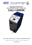
1
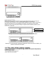
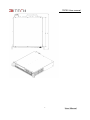
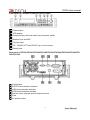
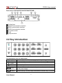
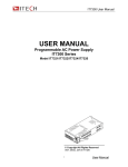
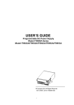
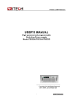
IT6700 User manual USER’S MANUAL Programmable HV Power Supply Model IT6700 Series IT6723/IT6724/IT6723C /IT6724C/IT6723B/IT6724B/IT6726B /IT6723H/IT6724H/IT6726H /IT6723G/IT6724G/IT6726G/IT6726V ©Copyright All Rights Reserved Ver1.1/OCT, 2012/ IT6700 1 User Manual IT6700 User manual IT6700 Series Programmable HV Power Supplies ............................................................... 3 Security ................................................................................................................................. 3 Security regulation ................................................................................................................ 3 Safety symbols...................................................................................................................... 3 Certification and Quality Assurance ...................................................................................... 3 Introduction ........................................................................................................................... 5 Chapter1 Inspection and Installation................................................................................................ 6 1.1 Inspection .................................................................................................................................................... 6 1.2 To Rack Mount the Instrument................................................................................................................. 6 1.3 The size of the power supply ................................................................................................................... 7 Chapter 2 Quick Start .......................................................................................................... 10 2.2 Key introduction........................................................................................................................................ 12 2.3 VFD Indicator Description ....................................................................................................................... 13 Chapter 3 power on check .................................................................................................. 14 3.1 power on Pre-check ................................................................................................................................. 14 3.1.1 Power on the supply ..................................................................................................................... 14 3.1.2 System self-check......................................................................................................................... 15 3.2 Output Checkout ...................................................................................................................................... 16 Chapter4 technical specification ......................................................................................... 17 4.1 main technical parameters ..................................................................................................................... 17 4.2 supplementary characteristic ................................................................................................................. 22 Chapter5 Basic operation ................................................................................................... 23 5.1 Local/Remote Mode ................................................................................................................................ 23 5.2 Voltage Setup ........................................................................................................................................... 23 5.3 Current Setup ........................................................................................................................................... 24 5.4 Output On/Off Operation ......................................................................................................................... 24 5.5 Setup value/Actual value switching ....................................................................................................... 24 5.6 Voltage/Current/Power adjustment........................................................................................................ 24 5.7 Save/recall Operation .............................................................................................................................. 25 5.8 Trigger operation ...................................................................................................................................... 25 5.9 Menu operation ........................................................................................................................................ 25 5.9.1 Menu description .......................................................................................................................... 25 5.9.2 Menu functions .............................................................................................................................. 27 5.10 OVP function .......................................................................................................................................... 31 5.11 Key Lock function ................................................................................................................................... 31 5.12 Remote sense function ......................................................................................................................... 31 Chapter6 Remote Operation Mode ............................................................................................ 33 6.1 RS232 interface........................................................................................................................................ 33 6.2 USB interface............................................................................................................................................ 34 6.3 GPIB interface .......................................................................................................................................... 35 User Manual 2 IT6700 User manual IT6700 Series Programmable HV Power Supplies Security Please do not install replacement parts in the instrument, or perform any unauthorized modification. Please send the instrument to our company's maintenance department for maintenance, to ensure its security features. Please refer to the manual for specific information warning or precautions to avoid personal injury or equipment damage. There is no part that the operator can maintenance. If maintenance service is required, please contact a trained service personnel. Security regulation To prevent electric shock, non-authorized personnel is strictly not allowed to open the machine. This equipment is strictly prohibited for use in life support systems or any other device with security requirements. We cannot accept responsibility for any direct or indirect financial damage or loss of profit that might occur when using the electronic load. Safety symbols Warning It reminds the user, note some operating procedures, practices, conditions and other matters, that may lead to human casualties. Notes: It reminds the user of some operating procedures, practices, conditions and other matters that may result in instrument damage or data lose for ever. Connect it to safety earth ground using the wire recommended in the user manual. High voltage danger The symbol on an instrument indicates that the user should refer to the operating instructions located in the manual. Certification and Quality Assurance IT6700 series programmable DC power supply fully meet all of the technical specification in the manual. Warranty Our Company provide one year warranty for the materials and manufacturing of the product since the date of shipment. 3 User Manual IT6700 User manual Warranty Service For the warranty service or repair the product, the product must be returned to the designated maintenance units. Return the product to us for warranty service, the customer should pre-pay the one-way Freight to the maintenance department. and our company is responsible for the return shipping cost. If products are returned from other countries for maintenance service, then the customer should pay all freight, duties and other taxes. Guarantee limit The guarantee does not apply to the damage caused by the following conditions: Improper or inadequate maintenance to the products by customer; Customers use their own software or interface; Unauthorized modification or misuse; ● Operate this product not in the specified environment, or at the wrong place configuration and maintenance. ● Damage from Customer self-installation of circuit, or defects due to customers use their products . ● Product model or serial number of the fuselage has been altered, deleted, removed or made illegible; ● Damage caused by accidents including but not limited to lightning, water, fire, abuse or neglect. Notice If the content of this manual is subject to change, we will not notice additionally User Manual 4 IT6700 User manual Introduction IT6700 series power supplies are high performance single-output programmable DC power supplied with communication interface. This series of programmable DC power supply can output the maximum voltage or current with a fixed power for customers. Take IT6723H (300V/10A/850W) for example, when you select 300V for the output voltage, the output power of IT6723H is 850W , so in this case the maximum output current is 850W/300V = 2.83A. When you select 85V for the output voltage, the maximum output current 850W/85V = 10A, but when the output voltage is down to 10V, due to IT6723H maximum current is 10A, so in this case the maximum output current is 10A. IT6700 series power comes with a standard communication interface RS232/USB/GPIB, both desktop and system-based features, can be designed and tested according to your needs and provide multi-purpose solutions. Convenient bench-top features: • High visibility vacuum fluorescent display (VFD) • Output is switch control • High accuracy and high resolution • Intelligent fan control, energy conservation, noise reduction • Standard communication interface RS232/USB/GPIB • Output voltage and current values accordance with procedure • Can use the knob to adjust the voltage and current • Can adjust the knob stepping using the cursor Model Voltage Current Power IT6723 80V 40A 850W IT6724 80V 40A 1500W IT6723B 150V 20A 850W IT6724B 150V 20A 1500W IT6723H 300V 10A 850W IT6724H 300V 10A 1500W IT6726H 300V 20A 3000W IT6723G 600V 5A 850W IT6724G 600V 5A 1500W IT6726G 600V 10A 3000W IT6726V 1200V 5A 3000W IT6723C 32V 110A 850W IT6724C 32V 110A 1500W IT6726B 160V 40A 3000W Optional Accessories: IT-E151 rack mount kit.(IT6726 not available) 5 User Manual IT6700 User manual Chapter1 Inspection and Installation Power supply is a high level safety equipment, there is a protected ground terminal. Before Installation or operation, please read the safety signs and instructions in this manual 1.1 Inspection After received the power supply, follow these steps to check it: 1. Check for damage in the equipment during transport If it is the frame, panel damaged, or abnormal working, etc. Please contact immediately with our authorized dealer or service department. Do not return the instrument before positive response has not been got. 2. Check the attachment Make sure you receive the power and the following components at the same time, if any missing, please contact your nearest dealer. □ a power cord (in accordance with the standard voltage used in the region) □ an operating manual. □ a factory calibration report Kinds of power cord E E E N L L E N N L L China IT-E171 USA ,Canada IT-E172 Europe IT-E173 N UK IT-E174 3. The power input requirements Working voltage for IT6723/IT6723B/IT6723C/IT6723H/IT6723G is 110V and 220V;Working voltageforIT6724/IT6724B/IT6724C/IT6724H/IT6724G/IT6726H/IT6726G/IT6726V/IT6726B is 220V, so please pay attention to the working input voltage. There is a power cord which matches with your local power in the attachment. If that does not match, please do not hesitate to contact with our authorized dealer or service department. AC input levels : (can choose via the switch on the bottom or power supply) Option Opt.01:220VAC ± 10%, 47 to 63 Hz Option Opt.02:110VAC ± 10%, 47 to 63 Hz 1.2 To Rack Mount the Instrument You can mount IT6700 power supply in a standard 19-inch rack cabinet using the IT-E151 (except for IT6726H/IT6726G/IT6726V/IT6726B) rack mount kit. Method to remove the handle: Pull up carrying handle to each outside, rotate it to vertical direction and pull out. User Manual 6 IT6700 User manual Install method of IT-E151 Remove the carrying handle and the two pale green stickers before rack-mounting the instrument on standard 19’’ IT-E151. Mounting specification is as following: Fix a plastic fitting screwed to the original handle installation position, then fix accessories 1 and mount accessories 2 to the following icon position. The method to fix two power supplies on rack is screw two plastic fittings in original handle installation position, mount accessories 1 after that. Accessories 1 Accessories 2 Drawing1.1 To rack mount a single instrument, order rack mount kit IT-E151 Drawing1.2 To rack mount two instruments side-by-side, order rack mount kit IT-E151, you needn’t to use the front cover panel. 1.3 The size of the power supply 1.SizeofIT6723/IT6724/IT6723B/IT6724B/IT6723C/IT6724C/IT6723H/IT6724 H/IT6723G/IT6724G: 214.5mmW×88.2mmH×445mmD *refer to the Dimensions below: 7 User Manual IT6700 User manual Unit:mm Size of IT6726H/IT6726G/IT6726V/IT6726B: 439mmW×88.2mmH×462mmD User Manual 8 IT6700 User manual 9 User Manual IT6700 User manual Chapter 2 Quick Start This chapter introduces the front panel, the rear panel, key functions and VFD display function of the power supply, make sure that you can quickly know the appearance, instruction and the key function before you operate the power supply, Help you make better use of this series of power supply. 2.1 The front and rear panel description FrontpanelofIT6723/IT6724/IT6723B/IT6724B/IT6723C/IT6724C/IT6723H/IT6724H/IT672 3G/IT6724G: + 1 VFD display 2 Rotary knob 3 Compound key, the local switch key and power switch 4 Number keys and ESC 5 Function keys 6 UP、DOWN, LEFT and RIGHT key, to move cursor 7 Output terminals User Manual 10 - IT6700 User manual Front panel of IT6726H/IT6726G/IT6726V/IT6726B: 1 Power switch 2 VFD display 3 Compound key, the local switch key and power switch 4 Number keys and ESC 5 Function keys 6 UP、DOWN, LEFT and RIGHT key, to move cursor 7 Rotary knob Rear panel of IT6723/IT6724/IT6723B/IT6724B/IT6723C/IT6724C/IT6723H/IT6724H/IT67 23G/IT6724G: 1 Cooling fans 2 RS232 Communication interface 3 USB Communication interface 4 GPIB Communication interface 5 Remote sense terminal and the output terminal 6 Fuse 7 AC power socket 11 User Manual IT6700 User manual Rear panel of IT6726H/IT6726G/IT6726V/IT6726B: 1 Cooling fans 2 RS232 Communication interface 3 USB Communication interface 4 GPIB Communication interface 5 AC power socket 6 Fuse 7 Output terminal 2.2 Key introduction Key description, see the table below: Keys Name and the function Compound key,co-work with OVP、Menu、Save、Trigger、Lock Shift Local Local switch key, switch from remote mode to local operation mode Power V-set OVP Power on key Numeric keys Voltage set key, set the output voltage/over voltage protection point for the power supply I-set Menu Current set key, set the output current/menu function key, to set the 0-9 User Manual 12 IT6700 User manual relevant Parameters for the power supply Recall Save Meter Enter Trigger On/Off Lock Callback key to call up a set value of system parameters already stored / storage key, to save system parameter settings Meter key, to switch from value set panel and the actual output value Enter key, to confirm the number entered and operation / trigger button, which is used to trigger the List test. Output on (off) keys, control power output state / keypad lock function keys, used to lock the panel buttons Left and right movement keys, used to set the value, to adjust the cursor to the specified location Up and down keys, used to select a item in the menu or increase (decrease) the output voltage or current values Cancel /return keys 2.3 VFD Indicator Description VFD indicator function description as follow: Char Function description Char Function description OFF Output is off Timer Output on timer function is ON CV CC The power supply is in Sense constant voltage mode The power supply is in Ext constant current mode No No (USB GPIB)light when the address match or (RS232) received order The power supply is in remote mode The power supply has error or fault * No Adrs Meter Meter mode Rmt Shift Use compound keys Error OVP OVP function state on Prot OVP /OTP/OCP Protection OCP OCP function state on Lock Key operation is locked 13 User Manual IT6700 User manual Chapter 3 power on check This chapter will introduce the procedure of power on check, including pre-check and output check, to make sure the IT6700 series power supply can power on and work normally on the original state. 3.1 power on Pre-check Before operate the power supply, please read the following safty guide: Warning:The power supply is shipped from the factory with a power-line cord that has a plug appropriate for your location. Your power supply is equipped with a 3-wire grounding type power cord; the third conductor being the ground. The power supply is grounded only when the power-line cord is plugged into an appropriate receptacle. Warning:Use wire with appropriately rated load capacity of all load wires must be able to withstand the maximum short-circuit output current of the power without overheating. If there is more than one load, each load wire must be able to safely carry the power of full rated short-circuit output current. Warning:In order to reduce the risk of fire and electric shock, make sure that the mains supply voltage fluctuations should not exceed 10% of the operating voltage range. Note: In some cases, misconfiguration mains voltage for the instrument may cause the mains fuse disconnect. Note:If use the power supply to charge the battery, be sure to pay attention to the battery's positive and negative polarity, otherwise it will burn out the power! Power on pre-check includes two parts: power on the supply and system self check. 3.1.1 Power on the supply Use the following steps to help solve problems you might encounter when turning on the instrument. 1) Verify that there is AC power to the power supply. First, verify that the power cord is firmly plugged into the power receptacle on the rear panel of the power supply. You should also make sure that the power source you plugged the power supply into is energized. Then, verify that the power supply is turned on. 2) Verify the power-line voltage setting. The line voltage is set to the proper value for your country (220VAC) when the power supply is shipped from the factory. Change the voltage setting if it’s not correct. User Manual 14 IT6700 User manual 3) Verify that the correct power-line fuse is installed. If the fuse was damaged, please see the table below to replace the fuse for your power supply. Model Fuse Specifications(220VAC) Fuse Specifications(220VAC) IT6723/IT6723B/IT6723C/I T6723H/IT6723G T15AT 250V T15AT 250V IT6724/IT6724B/IT6724C/I T6724H/IT6724G T15AT 250V Not available IT6726H/IT6726G/IT6726V /IT6726B T20AT Not available 250V 4) How to exchange the fuse Open the fuse box: Use a screwdriver to push and turn the fuse box on the rear panel of the power supply, refer to the below picture. After the fuse box is opened, you can see the fuse in it. Please replace with a fuse of the same specification. When install, use a screwdriver to push and turn the fuse box. Refer to the picture below. 3.1.2 System self-check After power on normally, the supply will enter self check test first. If the power supply is normal, then VFD will display the output voltage and current status as below: OFF 0.0V 0.00A About 1 second after power on,If the EEPROM was damaged or the latest operation data in EEPROM was lost, the VFD will display as below: EEPROM FAIL If the last power status in EEPROM is lost, then VFD will display information (about 1 S) as below: SYST LOST 15 User Manual IT6700 User manual If the calibration data in EEPROM is lost, then VFD will display (about 1S) as below: CAL LOST If the factory calibration data in EEPROM is lost, and then the VFD will display(about 1 S) as below: FACT LOST 3.2 Output Checkout The following procedures check to ensure that the power supply develops its rated outputs and properly responds to operation from the front panel. 3.2.1 Voltage Output Checkout The following steps verify basic voltage functions without load. 1) Turn on the power supply. 2) Set the current value(≥0.01A). 3) Enable the outputs Press On/Off key( On/Off key will be lit) to let the CV annunciator turn on to light. 4) turn on Meter mode press the METER key to light the button, the Meter status Mark lights on the display is turned on. 5) Set the voltage for the power supply Set different voltage values, check the voltage value displayed on the VFD is close to the voltage value you set, and to check if the VFD displayed current value is nearly zero. 6) Ensure that the voltage can be adjusted from zero to the full rated value 3.2.2 Current Output checkout 1) Turn on the power supply 2) Press On/Off key to ensure that the output is disabled. At the same time, the OFF status mark is on the VFD. 3) Connect a short across(+) and (-) output terminals with an insulated test lead, use a wire sufficient to handle the maximum current. 4) Adjust the voltage value to 1V. 5) Turn on the power output. Press On/Off key to ensure the output is enabled, at the same time there is CC status sign on the VFD. 6) Turn on METER function key. Press METER key to light it, and the METER status sign is on the VFD. 7) Adjust the current value Set some different current values, check whether the voltage value on VFD is near 0v, and the current on it is close to the value you set. User Manual 16 IT6700 User manual 8) Make sure that the current can be adjusted from 0 to full rated value. 9) Turn off the output of the power supply, and remove the short wire. Chapter4 technical specification This chapter will introduce the main technical parameters of IT6700H/IT6700G,such as rated voltage/current/power and so on. Besides, we will introduce the working environment and storage temperature. 4.1 Main technical parameters Parameters Rated values ( 0 °C~40 °C) Load regulation (%of output+offset) Line regulation (%of output+offset) Setup resolution IT6723C IT6724C 0 ~32V 0~110A voltage current power voltage current voltage current voltage 850W 1500W ≤0.01%+10mV ≤0.1%+20mA ≤0.01%+10mV ≤0.1%+20mA 10mV current 10mA voltage current 10mV 10mA Setup accuracy (one year)(25°C±5°C) (%of output+offset) voltage ≤0.01%+10mV current ≤0.1%+20mA Readback accuracy (one year)(25°C±5°C) (%of output+offset) voltage ≤0.01%+10mV current ≤0.1%+20mA Ripple voltage ≤80mVp-p current ≤150mA rms voltage ≤0.01%+10mV current ≤0.1%+20mA Readback resolution Temp.coefficient ( 0 °C~40 °C) Working temperature Dimension(mm) Weight(net) 0 °C~40 °C 214.5mmW×88.2mmH×445mmD 6Kg 17 User Manual IT6700 User manual Parameters Rated values ( 0 °C~40 °C) Load regulation (%of output+offset) Line regulation (%of output+offset) Setup resolution IT6723 IT6724 0~80V 0~40A voltage current power voltage current voltage current voltage 850W 850W ≤0.01%+10mV ≤0.1%+20mA ≤0.01%+10mV ≤0.1%+20mA 10mV current 10mA voltage current 10mV 10mA Setup accuracy (one year)(25°C±5°C) (%of output+offset) voltage ≤0.01%+10mV current ≤0.1%+20mA Readback accuracy (one year)(25°C±5°C) (%of output+offset) voltage ≤0.01%+10mV current ≤0.1%+20mA Ripple voltage ≤80mVp-p current ≤50mArms voltage ≤0.01%+10mV current ≤0.1%+20mA Readback resolution Temp.coefficient ( 0 °C~40 °C) Working temperature Dimension(mm) Weight(net) User Manual 0 °C~40 °C 214.5mmW×88.2mmH×445mmD 6Kg 18 IT6700 User manual Parameters Rated values ( 0 °C~40 °C) voltage current power voltage current voltage current voltage IT6723B 0~80V 0~40A 850W IT6724B IT6726B 160V 40A 3000W 3000W ≤0.01%+10mV ≤0.1%+20mA ≤0.01%+10mV ≤0.1%+20mA ≤0.01%+60mV 10mV 100mV current 10mA 10mA voltage current 10mV 10mA 100mV 10mA Setup accuracy (one year)(25°C±5°C) (%of output+offset) voltage ≤0.01%+10mV ≤0.01%+60mV current ≤0.1%+20mA ≤0.1%+20mA Readback accuracy (one year)(25°C±5°C) (%of output+offset) voltage ≤0.01%+10mV ≤0.01%+60mV current ≤0.1%+20mA ≤0.1%+20mA Ripple voltage ≤80mVp-p ≤200mVp-p current ≤50mArms ≤50mA rms voltage ≤0.01%+10mV ≤0.01%+60mV current ≤0.1%+20mA ≤0.1%+20mA Load regulation (%of output+offset) Line regulation (%of output+offset) Setup resolution Readback resolution Temp.coefficient ( 0 °C~40 °C) Working temperature 0 °C~40 °C Dimension(mm) 214.5mmW×88.2mmH×445mmD 6Kg Weight(net) 19 ≤0.1%+20mA ≤0.01%+60mV ≤0.1%+20mA 0~40°C 439mmW×88.20m mH ×462mmD 13Kg User Manual IT6700 User manual Parameters Rated values ( 0 °C~40 °C) Load regulation (%of output+offset) Line regulation (%of output+offset) Setup resolution IT6723H voltage current power voltage current voltage current voltage IT6724H 0 ~300V 0~10A 850W 1500W ≤0.01%+60mV ≤0.1%+20mA ≤0.01%+60mV ≤0.1%+20mA 100mV current 10mA voltage current 100mV 10mA Setup accuracy (one year)(25°C±5°C) (%of output+offset) voltage ≤0.01%+60mV current ≤0.1%+20mA Readback accuracy (one year)(25°C±5°C) (%of output+offset) voltage ≤0.01%+60mV current ≤0.1%+20mA Ripple voltage ≤150mVp-p current ≤30mA rms voltage ≤0.01%+60mV current ≤0.1%+20mA Readback resolution Temp.coefficient ( 0 °C~40 °C) Working temperature Dimension(mm) Weight(net) User Manual 0 °C~40 °C 214.5mmW×88.2mmH×445mmD 6Kg 20 IT6700 User manual Parameters Rated values ( 0 °C~40 °C) Load regulation (%of output+offset) Line regulation (%of output+offset) Setup resolution Readback resolution Setup accuracy (one year)(25°C±5°C) (%of output+offset) Readback accuracy (one year)(25°C±5°C) (%of output+offset) Ripple voltage current power voltage current voltage current voltage 0~600V 0~5A 850W ≤0.01%+100mV ≤0.1%+10mA ≤0.01%+100mV ≤0.1%+10mA 100mV 10mA voltage current 100mV 10mA voltage ≤0.01%+100mV current ≤0.1%+10mA voltage ≤0.01%+100mV current ≤0.1%+10mA voltage ≤150mVp-p ≤20mA rms ≤30mA rms voltage ≤0.01%+100mV current ≤0.1%+10mA 0-40℃ Working temperature Dimension(mm) 1500W current current Temp.coefficient 0-40℃ IT6724G IT6723G 214.5mmW×88.2mmH×445mmD 6Kg Weight(net) 21 User Manual IT6700 User manual voltage current power IT6726H 0 ~300V 0~20A 3000W IT6726G 0 ~600V 0~10A 3000W Load regulation (%of output+offset) voltage ≤0.01%+60mV ≤0.01%+100mV current ≤0.1%+20mA ≤0.1%+20mA Line regulation (%of output+offset) voltage ≤0.01%+60mV ≤0.01%+100mV current voltage ≤0.1%+20mA 100mV ≤0.1%+20mA 100mV IT6726V 0~1200V 0~5A 3000W ≤0.01%+200m V ≤0.1%+20mA ≤ 0.01%+200mV ≤0.1%+20mA 100mV current 10mA 10mA 10mA voltage current 100mV 10mA 100mV 10mA voltage ≤0.01%+60mV ≤0.01%+100mV current ≤0.1%+20mA ≤0.1%+10mA 100mV 10mA ≤0.01%+200m V ≤0.1%+10mA voltage ≤0.01%+60mV ≤0.01%+150mV current ≤0.1%+20mA ≤0.1%+10mA ≤0.01%+200m V ≤0.1%+10mA voltage ≤250mVp-p ≤300mVp-p ≤600mVp-p current ≤30mA rms ≤30mA rms voltage ≤0.01%+60mV ≤0.01%+100mV current ≤0.1%+20mA ≤0.1%+20mA ≤0.01%+200m V ≤0.1%+30mA 0-40℃ 0-40℃ Parameters Rated values ( 0 °C~40 °C) Setup resolution Readback resolution Setup accuracy (one year)(25°C±5°C) (%of output+offset) Readback accuracy (one year)(25°C±5°C) (%of output+offset) Ripple Temp.coefficient 0-40℃ Working temperature 0-40℃ 439mmW×88.20mmH×462mmD 439mmW×88.20mmH×462mmD Dimension(mm) Weight(net) 13Kg 13Kg 4.2 Supplementary parameters Memory :9×8 groups suggested calibrationfrequency:1time/year Max input AC power IT6723/IT6723B/IT6723H/T6723G 1100VA IT6723C 1150VA IT6724/IT6724B/IT6724H/IT6724G 1850VA IT6724C 1900VA IT6726H/IT6726G/IT6726V/IT6726B 3700VA User Manual 22 ≤30mA rms IT6700 User manual Radiating mode :Fans Operation temperature:0 to 40 °C Storage temperature:-20 to 70 °C. Humidity :Max humidity: 80% Chapter5 Basic operation This chapter will introduce the basic operation of IT6700 series power supply,including the following subdivisions: Local/remote mode Voltage setup Current setup Output on/off operation Setup value/actual value switching Voltage/current/power adjustment Save/recall operation Trigger operation Menu operation OVP protection function Key lock function Remote sense function 5.1 Local/Remote Mode Local button can enable you switch mode from remote to local mode. After you power on the power supply, the power supply’s default mode is local mode, all the buttons can be used in this mode. While in remote mode, you can’t operate through front panel directly except Meter and Local keys. Local and remote mode can be controlled through PC. In addition, the mode changing will not influence the output parameters. 5.2 Voltage Setup You can set voltage within the range of rated voltage value. When you press V-set button, the button will be lit. This indicates that you can set voltage. There are three ways to set output voltage through front panel. button, pressing The first way: press V-set ,adjust cursor location through and will enable you to adjust the setting voltage value. The second way: press V-set , adjust cursor location through button, adjust rotary knob to change the setting voltage value. The third way: press V-set button and number key( 23 0 to 9 ) to set voltage value User Manual IT6700 User manual 5.3 Current Setup You can set current within the range of rated current value. When you press I-set button, the button will be lit. This indicates that you can set current. There are three ways to set output current through front panel. The first way: press I-set ,adjust cursor location through button, push and will enable you to adjust the setting current value. The second way: press I-set ,adjust cursor location through button, adjust rotary knob to change the setting current value. The third way: press I-set button and number key( 0 to 9 ) to set current value 5.4 Output On/Off Operation On/Off button is used to control the output state of power supply. When On/Off button is lit, this indicates the output is in on mode. When output is open, the working state indicator light(CV/CC) will be lit. Note: make sure you have connected power supply and the test unit well, then press On/Off button. If there is no voltage output, you should first check the voltage and current set. 5.5 Setup value/Actual value switching You can switch the display between setting value and actual value by pressing Meter button. When this button is lit, screen displays actual output value and the indicator light “Meter” will be lit on the VFD. In other words, when the button is not lit, the front panel displays setting value. 5.6 Voltage/Current/Power adjustment The output current value is determined by output voltage of power supply and electronic load’s resistance. Only when the actual current value is lower than the setting current value, can power supply work in CV mode and the will CV indicator light be lit. If output current is higher than the setting value, then power supply will function in CC mode. And the CC indicator light will be lit. The output voltage and current value are also influenced by the upper limit of output power. Take IT6723H (300V/10A/850W) for example, suppose you set the voltage to 100V, then the current can just reach 8.5A(limited by the power). User Manual 24 IT6700 User manual 5.7 Save/recall Operation Customer can save some often-used parameters in nonvolatile memory. You can use the button (Shift)、 Recall (Save) button or SCPI order *SAV、*RCL to achieve this function. Saving parameters include: 1. setting voltage 2. setting current 3. OVP value 4. OCP value Saving operation: Press (Shift)+ Recall (save) button( Recall button will flash), and then input the group number you want to save through number key board. Press Enter button to confirm. Recall operating: Press Recall button( Recall button will lit), and press corresponding group number(number1-9).At last press Enter button to confirm. Note: the memory capacity is 9*8, which indicate 8 memory groups and 9 memory in each group. The memory group you use at the present should be selected in the Menu(MEM GROUP)., refer to chapter 5.9. 5.8 Trigger operation The trigger source of IT6700 include manual and BUS, manual means trigger by button of the front panel, and BUS means trigger by command from the PC. You need to select the trigger source(TRIG) from the menu before using this function. (Shift)+ Enter (Trigger)to give a trigger signal. After you edit a list file, press During the running process, Enter button will flash all the time. 5.9 Menu operation 5.9.1 Menu description Press (Shift)+ I-set (Menu) to enter the menu. You will see a optional items on the screen, through direction keys and rotary knob to overturn VFD display, then the screen will display the following functions .Press Enter button will enter corresponding items. Press ESC button will return to previous menu. MAX VOLT OCP SET SYST SET Set the max voltage output limit OFF Disable the OCP function ON enable the OCP function Power on parameter is restored to factory Reset P-MEM setting (RESET) Set the power-on parameter as the last Keep power off state OFF Set the power-on output state to be Offt P-OUT (OFF) Set the power-on output state to be the last Keep power-off output state 25 User Manual IT6700 User manual Address can be set within 0-30 4800 9600 19200 BAUD 38400 57600 115.2K RS232 NONE 8BIT NONE 8BIT EVEN 8BIT ODD 8BIT SIGNAL MODE Address can be set within MUX 0-30 USB Select USBcommunication interface OFF Disable the key sound ON Enable the key sound LOCK Lock the rotary knob function ON Un-lock the rotary knob function MANU Local keyboard trigger BUS Trigger by command Select memory group for Save and recall GRP1-8 operation OFF Disable the timer function Enable the timer function, time range ON 0.1-99999S NO keep the present settings YES restore the factory setting Quit the menu setting OFF Set the LIST state as OFF ON Set the LIST state as ON Re-load the LIST file(FILE0-FILE9) SEC Second TIME (SEC) MIN Minute VSET Set the voltage for present step ISET Set the current for present step SEC Setup single step delay time (0.1-9999) YES continue the edit of next step NEXT (YES) NO End up the list file edit REPET 1-65535 Set the cycle count of list file NO Un-save the current LIST file SAVE Save the list file to appointed FILE0-FILE9 memory Exit the system menu Unit model the software version GPIB COMM (GPIB) BEEP (ON) KNOB (ON) TRIG (MANUAL) MEM (GROUP1) TIMER SET RESET EXIT LIST SET LIST STATE LIST LOAD LIST EDIT POWER INFO User Manual EXIT MODEL ITXXXX VER ADDR 26 IT6700 User manual the first six number of SN the middle six number of SN the last six number of SN Exit the information menu Exit the main menu SN-1 XXXXXX SN-2 XXXXXX SN-3 XXXXXX EXIT EXIT MENU Note:Pressing 5.9.2 ESC button can enable you to quit any function setting. Menu functions Maximum voltage set(MAX VOLT) The range of setting voltage is from 0V to rated voltage. You can press (Shift)+ I-set (Menu) button to enter the menu, then press 、 key to select >MAX Enter VOLT item. Press button to confirm. After you set the max voltage value, the output voltage value can only be set within the max voltage. The default max voltage value is the rated value. Over current protection set(OCP SET) Over current protection feature allows the user to set an over current protection point, when the current in the circuit is larger than the current protection point, the power supply will enter OCP protection. Over current protection, power output will be off, and accompanied by the chirping of the buzzer, the VFD mark Prot will be lit, and the emergence of "OVER CURR" alarm The operation to set the OCP point: Press (Shift)+ I-set (Menu)button to menu, press 、 to overturn to OCP SET , 、 to select ON,press Enter to confirm, set OCP point by press Enter button,and Esc pressing numeric keys, then press Enter . At last, press to escape. Esc Power-on parameters set (P-MEM) This item can set power on parameters. If you select RESET item, then all the parameters will be initialized to the factory setting. Output voltage and current will always be 0V/max rated current; if set to Keep, the output value will be the same with last power off state. The default setting is RESET item. Power On Output State(P-OUT ) This item can set the power on output state. If you select KEEP item, that indicates the power on output state is the same with output state before this item is set. If you select Off item, unit will automatically in off mode when you power on. Default setting is Off item. 27 User Manual IT6700 User manual Communication (COMM ) Our unit has provided three standard communication interfaces: RS232/USB/GPIB.In this option, you can select the communication interface according to your demands. The range of GPIB address is 0-30. Besides, we have multi-baudrate to be chosen in RS232 mode---4800,9600,19200,38400,57600,115.2K.Data bit is 8,Check digit have three choices: NONE,ODD,EVEN.Before you begin to carry out communication,please make sure the configure in our unit agrees with PC configure. Key Sound Set(BEEP ) This item can set the key sound state.If in On mode, the power supply will issue beeper sound when you press any button.If in Off mode,the beeper will not make a sound.The default set is in on mode. Rotary Knob Set(KNOB ) This item is used to set rotary knob state.In On mode,you can use this rotary knob to set the output value and overturn the menu items.In Lock mode,this knob can’t be used.The default setting is in On mode. Trigger source(TRIG ) Before you running a list file, you need a trigger signal.Thus you must set the trigger mode first: keyboard trigger or command trigger. In MANU trigger mode,press (Shift)+ Enter button can generate a trigger signal. In BUS trigger mode,you can only trigger through sending command. The default set is MANU option. Memory Group Set(MEM GROUP) Power supply can save some often-used parameters in a nonvolatile memory(capacity is 9*8 groups).This function can make the operations more convenient. Customer can save and recall parameters quickly. GRP1:This indicates saving power supply parameters in 1-9 groups.Press (Shift)+ Recall (Save) and the group number(1-9) can save the parameters in corresponding groups. GRP2:This indicates saving the parameters in 10-18 groups.Press (Shift) + Recall (Save)+saved group number(1-9)can save related parameters.Note that the current number “1” represents parameters are saved in 10th groups.Number “2” represents the parameters are saved in 11th groups. User Manual 28 IT6700 User manual GRP3-GRP8 by parity of reasoning. Detailed Save and Recall operation refer to chapter 5.7. Timer Set(TIMER SET) This item is used to set the “time on- load” function, time range 0.1-99999S .In ON mode,the indicator light “Timer” will be lit on the VFD screen.When output of power supply is opened,timer will begin to work,after reaching the definite time,output will be off automatically.If in OFF mode,the timer function will not be enabled.The default set is OFF Reset(RESET) This item is used to reset all items in the menu.If you select YES,then unit will restored to factory setting.If you select NO,all settings in the menu will remain unchanged. List(List Set) IT6700 series power supply provides 9 list files,each list file includes 150 steps. Before you edit a list file,please set the trigger mode:manual mode. (Shift)+ I-set (Menu)button to enter the menu,then press direction key to Press select >SYST SET option,after that please push Enter button to confirm.At last to press direction key to select >Trig MANUAL and push Enter button to confirm. You can make the output change order by editing every step value of list operation. The parameters you need to edit includes:single-step voltage,single-step current,single-step delay time and whether to go on the next step.Besides,you also need to set the repeat times and save list sequence file.After the editing process,at this time if a trigger signal is received,power supply will begin to work according to the sequence steps you’ve edit. Now we take five steps for an example: Operation steps: (1) Press (Shift)+ I-set (Menu)button to enter the menu (2) VFD display >MAX VOLT,press to select >LIST SET,press Enter to confirm Enter to confirm (3) VFD display >LIST STATE,press to select >LIST EDIT, press Enter to confirm,go to the next step,you can also (4) VFD display >TIME SEC,press through Enter button to select >TIME MIN time unit,press (5) VFD display >VSET 0.0,press number key voltage,after that press Enter to confirm. (6) VFD display ISET 0.00, press number key single-step current, press Enter to confirm. 0 to 0 to 9 to confirm. or through rotary knob to set 9 or rotary knob to set the (7) VFD display SEC 0.100,press number key 0 to 9 or rotary knob to set single-step delay time,press Enter to confirm(range is 0.1-9999). If you choose MIN for the 4th step, VFD will display MIN 0.100 for this step, time range 0.1~9999min. 29 User Manual IT6700 User manual (8) VFD display NEXT >YES,press Enter to confirm. (9) Repeat the steps from 5) to 8) and set the four steps’ voltage/current and delay time separately. When screen display NEXT>YES in the fourth step edit process,please press to select NEXT >NO,press Enter to confirm. (10) VFD display REPET 1,press number key 0 to 9 or rotary knob to set the repeat times,press Enter to confirm. (11) VFD display SAVE >NO,press Enter to confirm,in this circumstance,the list file is not saved but can run for one time,or you can press button to select >SAVE Enter to confirm.You can recall the FILE0,saving the list test file in FILE0~FILE9,press file in the following utilization. (12) If you do not save the list test file,VFD will display LIST EDIT;if you select to save the test file,VFD will display SAVE DONE for three seconds,and then display LIST EDITL. Set List State to select >LIST STATE item,press (13) Press Enter to confirm. (14) VFD display LIST >OFF, press to select >LIST >ON, press Enter to Enter button will be lit.This indicates that list operation function has been confirm.Now opened. (15) VFD display >LIST STATE,pressing Run list file (16) Press On/Off a trigger signal. Esc button can quit the operation. button to open the output,press (Shift)+ Enter (Trigger)to give Recall list file (17) If you have edited several list files,you can select LIST LOAD item to recall the file Esc to quit this operation.Press On/Off button to open the you need.And then press output.Now you only need to press (Shift)+ Enter (Trigger) to give a trigger signal,the list file can be ran. Quit list file (18) In LIST mode,voltage set and current set button can’t be used,In LIST STATE item,choose LIST>OFF will enable you to quit list mode. User Manual 30 IT6700 User manual Trigger Trigger 5.10 OVP function IT6700 series power supply provide OVP function,press (Shift)+ V-set button can enable you to set the over voltage protection level.Over voltage may caused by internal defect or customer’s incorrect operation(such as output voltage rising),or a too high external voltage.Once OVP function is triggered,the output will be off immediately and “OVP” indicator light will be lit,the VFD display “OVER VOLT”。 Avoid external voltage that across the output terminals exceeding the 120% of rated voltage or it will damage out power supply! When power supply in OVP state,please check the external factors first, after you exclude the external factors, press ON/OFF button to open output again.If in communication state originally, you should by sending order OUTP ON order to open output. 5.11 Key Lock function Press (Shift)+ On/Off (Lock)button to set the key lock state.If keyboard has been locked,the indicator light Lock will display on the VFD screen.In addition,when key board are lock,all butttons can’t be used but ON/OFF、Meter buton、shift button.Press this button once again will relieve key lock function. 5.12 Remote sense function Vo+,Vo- :output terminals,the same with front pannel output terminals ; Vs+,Vs- :remote sense pins. Disconnect the wires between “+,-”pins if you want to use remote sense function.Then lead a wire from S+,S- pins and connect to the under test objects. 31 User Manual IT6700 User manual Remote sense function Remote sense can adjusted at the output voltage of the device under test, this feature allows to compensate the voltage drop on the wire between the front panel terminals of the power supply and the device under test. Use local sense: Local sense doesn’t compensate the voltage drop on the connection wire, the operation is: 1. Use the short clips on the back panel of the instrument, or install wire between Vo+ and Vs+ 、Vo- and Vs2. Connect the the positive and negative terminals of the front panel to the device under test Use remote sense: 1. Disconnect the wires/short clips between Vo+ and Vs+、 Vo- and Vs2. Connect wires from Vs+ 、Vs- to the device usder test 3. Connect wires from Vo+ 、Vo- to the device under test Note: In order to ensure the stability of the system, using armored twisted pair cable between the remote sense terminal of IT6700 and load. Please note that the positive and negative polarity when wiring, otherwise it will damage the instrument! Vo+ Vs+ Vs- Vo- User Manual 32 IT6700 User manual Chapter6 Remote Operation Mode IT6700 series power supply three standard communication interface: RS232, USB, GPIB, the user can choose any one of them to implement a communication with the computer. 6.1 RS232 interface There is a DB9 connector at the rear of the power supply, when connect to computer, you need to select a cable with COM port on both side; To active communication,you need to enable the settings in menu to be the same with the PC communication configuration. Note:The RS232 settings must match the settings in front panel system information. If any change, please press (Shift)+ I-set key to modify the menu: SYST SET\COMM. RS-232 data format RS-232 data is a 10-bit words which has a start bit and a stop bit. The start bit and stop bit can’t be edited. However, you can select the parity items with (Shift)+ I-set key on the front panel. Parity options are stored in nonvolatile memory Baud Rate The front panel (Shift)+ I-set button allows the user to select a baud rate which is stored in the non-volatile memory: 4800,9600,19200 38400,57600,115200 RS-232 connection cable Use a RS232 cable with DB-9 interface, RS-232 serial port can connect with the controller (eg PC). Do not use blank Modem cable. Below Table shows the plug pins. If your computer is using a RS-232 interface with DB-25 connector, you need an adapter cable with a DB-25 connector at one end and the other side is a DB-9(not blank modem cable) 33 User Manual IT6700 User manual RS-232 plug pins Pin number Description 1 No connection 2 TXD, transfer date 3 RXD, receive data 4 No connection 5 GND, ground 6 No connection 7 CTS, clear transfer 8 RTS, ready to transfer 9 No connection RS-232 Troubleshooting: If there is RS-232 connection problem, check the following: Computer and power supply must configure the same baud rate, parity, data bits and flow control options. Note that the power configuration as a start bit and a stop bit (these values are fixed). As described before in RS-232 connector, you must use the correct interface cable or adapter. Note that even if the cable has the right plug, the internal wiring may be wrong. Interface cable must be connected to the correct serial port on the computer (COM1, COM2, etc.). Communication Settings Before communication, you should first make the following parameters of power supply and PC matches. Baud Rate: 9600 (4800,9600,19200,38400,57600,115200). You can enter the system menu from the front panel, and then set the baud rate. Data bits: 8 Stop Bits: 1 calibration (none, even, odd) EVEN 8 data bits, have even parity ODD 8 data bits have odd parity NONE 8 data bits, no parity Local Address: (0 ~ 31, the factory default setting is 0) Parity=None Start Bit 8 Data Bits Stop Bit 6.2 USB interface Use a Cable with two USB port to connect the power and the computer. All power functions can be programmed via USB. The USB488 interface functions of the power supply described as below: interface is 488.2 USB488 interface. User Manual 34 IT6700 User manual Interface Receiver REN_CONTROL, GO_TO_LOCAL, and LOCAL_LOCKOUT request. Interface receive MsgID = TRIGGER USBTMC order information, and will pass TRIGGER order to the functional layer. Power USB488 device functions described as follows: devices can read all of the mandatory SCPI orders. device is SR1 enabled. device is RL1 enabled. device is DT1 enabled. 6.3 GPIB interface First, Connect the GPIB interface on the power supply and the GPIB card on computer via IEEE488 bus, must be full access and tighten the screws. Then set the address, the address range of the power : 0 to 30, can set by the function key on the front panel, press the (Shift)+ I-set key to enter the system menu function, find the GPIB address setting ▼ button, type the address, Enter key to confirm. GPIB address is stored in by nonvolatile memory line. Note: Forbidden to connect DB9 connector in power supply directly with PC or other RS232 port. 35 User Manual IT6700 User manual Support process If you have a problem , follow these steps: 1 Check the documentation that come with the product 2 Visit the ITECH online service Web site is www.itechate.com ,ITECH is avaliable to all ITECH customers. It is the fastest source for up-to-date product information and expert assistance and includes the following features : Fast access to email AE Software and driver updates for the product Call ITECH support line 025-52415098 User Manual 36