1
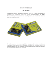
INDEX
User Manual
v1.0
Ref: DS 0085
1.
2.
3.
4.
5.
1.
2.
3.
6.
7.
8.
9.
10.
11.
12.
Introduction
Specifications
How to use
Displays and selectors
Basic set up
Power control and power maps
Brake settings and TTS
Traction control
Bidirectional wireless telemetric
Lap detector
Fuses and protection
Free downloads
FAQ’s.
Usual solutions.
Warranty.
1. Introduction
Thank you for purchasing the DS-Witec Controller, it has been developed over the last several years by us using our Slot Racing
enthusiast engineering. With DS-Witec Controller we tried to manufacture a electronic controller to provide new up today features in scale
competition. Please take several minutes to read this operation manual to get the needed knowledge on all provided controller characteristics.
After reading this operation manual you can get the maximum performance from this DS Witec. If there any questions please contact your
local shop or contact DS- Racing Products.
Yours sincerely,
DS Witec Engineering team.
2. Specifications
DS Witec electronic controller main specifications are:
• Free contact trigger with optical sensors and infrared barrier.
• Beside the traditional advanced braking system, we offer also TTS advanced braking system. This braking system works directly with the motor to reduce its speed to force it to speed down to your trigger position, and with it is much easier to improve performances in complex curved track sections. It is possible to activate or deactivate this advanced TTS braking system with an easy button to return to normal controller brake system.
• 64 pre-saved power maps stored in 4 different memory banks. Fully editable from PC software using the wireless connection through our USB receiver*
• Traction controller to allow better grip in accelerations and avoid skidding.
• Wireless telemetry on PC* allow reception data of all details on trigger use, live regulations done in the controller, lap to lap timing** and lap section timing ** on DS Witec software. Telemetric data is fully password protected by using the ISM 2.4 GHz. band.
• Motor and braking control done by PWM system.
• Minimum distance between track power supply and controller power box to avoid voltage looses on wiring.
• Low weight and compact design.
• Ergonomic and compact handle.
•1 or 2 finger trigger option supplied
Manufacturing specifications
• ROHS compliant.
Contents:
• 1 x DS WiTEC Controller.
• 1 x user manual.
* USB Emitter/receiver will be sold separately.
**Available soon with new updated DS Stop&Go track/controller connection boxes.
3. How to use
Banana plug Colors
Function
White
V+ from power supply
Black
Motor
Red
Ground
Table 1. Banana plugs colors equivalences and functions.
DS Witec Controller is designed to work on Analogical slot
tracks. It came with 3 colors 4mm banana plugs, designed to follow the
standard colors from all DS Racing Products.
Description
ENG
Value
9 volts with brake,
Minimum Voltage use 6 volts without brake
22 volts
Maximum Voltage use Maximum continuous current 3 amperes
Máximum top current allowed
7 ampers
DS WiTEC is protected with easy interchangeable fuses
assembled on wiring coming from white and red Banana plugs. It is the
best protection against damage, on electronic board when a short-circuit
or wrong track plug connection happens. This does not affecting the
maximum power or performance of the power supplied either for brakes
or acceleration to your car.
To allow full functionality of the DS-WITEC controller you
must plug in the 3 banana plugs. If you wish to disconnect the braking
system, do not unplug the red plugs, use your braking knob selector
turned to 0.
Table 2. Operation limits.
DS Witec controller maximum voltage supplied is what is provided from the power supply. On braking position, the controller
does not supply any additional negative power to the brake. This two standard facts makes this controller fully legal to all kind of races worldwide.
DS Racing Products reserves the right to cancel the warranty in case that warranty seals are damaged or there is clear evidence that
it has been incorrectly used. Examples are physic damage, internal manipulation or modification or used outside the operation range values
from table 2.
4. Displays and Selectors.
11
The controller has the following displays and selectors:
1. Contact less trigger.
2. Rotating Power map Knob Regulator with 16 positions.
3. Rotating Braking adjustment knob regulator.
4. Rotating Traction control adjustment knob regulator.
5. Wireless Telemetry on/off switch.
7
6. Power map bank selector with 2 switches for a total 4
memory banks.
7. Multifunction button:
• TTS on/off function.
• Telemetry channel change
• Starting wireless data reception from PC Software.
8. LED display with alphanumeric indicator
9. LED power indicator.
10. Stereo 3.5mm jack connector for lap synchronizing.
11. RPSMA antenna plug.
8
1
5
6
2
3
4
10
9
5. Basic Setup
5.1. Power control and power maps.
Bank number
Slot Racing discipline
1
2
3
4
16 rallyslot 1/32 power maps
16 rallyslot 1/24 power maps
16 sprint or endurance 1/32 power maps
16 sprint or endurance 1/24 power maps
DS WiTEC has a total of 64 power maps in 4 different memory banks. Those power maps are fully wireless editable by the user
using a USB accessory sold separately. Each of the 4 bank contains 16
preset factory optimized power maps. According to table 3 indications.
Table 3. DS Witec memory banks.
Memory bank selection is made through Micro DIP selector 1
and 2.
Memory bank
1
2
3
4
Micro DIP selector
Dip. 1
Dip. 2
OFF
ON
OFF
ON
OFF
OFF
ON
ON
Table 3 b. DIP configuration for memory bank selection.
While memory bank selection is being done, bank number is visible on LED alphanumeric display blinking for 1 second.
Each power map is identified with a number or letter, and it is visible on the LED alphanumeric display permanently, when rotative power
map know selector is being used the LED blinks for a few seconds showing the selected curve. For a right handed driver, on a top controller
view, power map increase is done clockwise. Power map numbering starts from 0 to 9 and continues from “A” to “F”.
Picture 1. Number and letter LED display clockwise Sequence for power map
selection.
Picture 2. Number and letter LED display anticlockwise Sequence for power map
selection.
Original preset power maps are incremental, the setting of them is based in that the low number are less strong power maps and
ending up on F power map as most radical.
5.2.-Brake setting and TTS.
It is very important to set up the correct brake adjustment to obtain the best performance of your car on track. For this reason,
with DS-Witec we engineered an advanced braking system as well as fitting the traditional brake.
ENG
The new TTS braking system means “True Trigger Speed” and is a combination of acceleration and brake to force the motor to
work on trigger position without the motor inertial movement. TTS system also affects the way that current circulates inside the motor, this
makes for better motor magnetic induction, making more traction in the curves. TTS can be deactivated and then the braking works as usual
when trigger reach the rest position.
To select TTS or traditional braking system is done with the button fixed on one side of the controller, over the trigger. This selection is saved in memory, so next time you use the controller it will keep the last configuration fixed.
When TTS is active the LED display will show permanently a “period” under the power map selection
Figure 3. Sample of F power map selected with TTS activated.
With the Brake knob regulator is possible to adjust from 0% to 100% .
5.3.-Traction Control (Antispin)
Traction Control supplies better acceleration on slippery or low grip tracks, as it helps prevent spinning the wheels and helps provide maximum traction between tyres and track. The antispin knob, regulates the traction control from disconnected to maximum value. The
optimal setup depends on various factors, like driving style, track technicality, track grip and car configuration. With a lot of traction (grip)
when racing is possible that the traction control will make the car slower, in this case it is better to not activate it.
6. Bidirectional Wireless Telemetric
With the new USB receiver (Ref. DS-0089), is possible to receive on your PC all Telemetric data from the controller and send to
the controller all power map modification parameters.
6.1. Telemetry ON/OFF switch
On the DIP Switch, number 3 selector allows you to activate or disconnect the wireless telemetry. We strongly recommend that if
you will not use, disconnect it.
Off
On
6.2.How to select the communication channel
DS Witec data works in 16 different radio communications channels. Each channel allow more than 1 controller, To select the
communication channel do as follows:
• Unplug the controller from the track connection with power on.
• Push the handle button (same as TTS button).
• While button is being pushed connect the controller to track connection with the power on. Avoid touching the trigger while carrying out this procedure.
• LED display shows the actual configuration of the channel, if this is the first time of adjustment it will show the original factory channel adjustment that is 0.
• Release the button.
• With quick presses on the button you can choose the channel.
• By pushing the trigger you can select the channel chosen. Afterwards the controller operates in the new selected channel and starts with its usual working.
6.3. Telemetry Data protection.
As the Telemetry data is confidential it is protected by password fully editable by the end user. AS it is possible to forget the password, you can return to factory default password doing the following sequence. Original factory default password is: “abcde” .
To recover the factory default password:
• Unplug the controller from the track connection with power on.
• Fix all 3 DIP selectors in OFF (Memory bank and telemetry activation)
• Push the handle button (same as TTS button).
• While button is being pushed connect the controller to the track connection with power on. Avoid
touching the trigger while carrying out this procedure.
• LED display shows the actual configuration of channel.
• Release the button.
• Move down DIP num.3 to ON position.
• Move down DIP num.2 to ON position.
• Move down DIP num.1 to ON position.
• Move up DIP num.1 to OFF position.
• Move up DIP num.2 to OFF position.
• Move up DIP num.3 to OFF position.
• LED displays show “P”.
• Confirm the default factory setup by pulling the trigger. With a second pull of the trigger the controller starts working normally.
The controller has now recovered the default factory password and also the channel is changed to 0.
When you want to receive updated power maps or change the password is necessary to press the handle button for more than 1 second, when
releasing the button, an “H” letter will show on the LED display, at this moment if there is any data to receive from the PC, it will be shown
on the PC display. For more specific telemetric functions is needed to check the operation manual for DS Witec Software.
7. Lap Detector
With the new Stop& Go boxes (Ds-0118) is possible to receive lap or partial lap section signals to the DS Witec,. With these signals it is possible to analyze the telemetric more accurately and allows you to do lap by lap analysis and comparatives. To get the lap detection
you need to plug the Stereo jack 3mm. To the Ds stop and go connections.
8. Fuses and protections
ENG
DS WiTEC is equipped with protection fuses for VCC and Ground. If in any case the fuses are broken replace them for new 5Amp
ones. Do not change for higher amperage fuses as this can damage the controller and will not increase the controller performance.
9. Free Downloads
Please visit WWW.DS-RACINGPRODUCTS.COM to download updated extra features and contents for DS WiTEC, also is
possible to download optimized power maps done by professional drivers for any kind of track conditions already tested.
10. FAQ
Why does this controller brake more than other controllers ?
The plug track connection distance to the DS Witec power box is reduced, besides this design, we have selected the most efficiency
transistors to warranty the best performance. As well as the exceptional brakes, the voltage supplied when maximum power is given also has
no loss of power.
I see on the power supply readings above the voltage being supplied to the track. Does DS WiTEC generates peaks?
No, DS WiTEC do not generate any type of peaks, Overvoltage observations on voltmeters from some power supply are based in
the fact that in some circumstances the car motor acts as generator.
I’m on the track and the car is faster without TTS and without Traction Control?
When the car grip is optimal, the driving aids like traction control and TTS may not help you achieve the best lap timing. In endurance races the driving aids are better to get a constant lap timing and avoid accidents. As always the set up depend a lot on cars, track, race
style, voltage and drivers.
I have a Laptop with WIFI and Bluetooth, will this allow me to receive the Telemetry and edit DS-Witec power maps controller?
No, DS WITEC do not uses WIFI or Bluetooth, it is necessary to purchase the USB accessory (DS-0089) to get communication
with the controller.
I have an “H” on LED display while keeping the button TTS connected/disconnected.
By holding the controller button for a long time, instead of connecting or disconnect the TTS braking system you are setting up
the controller to receive telemetry data. With a trigger push the “H” disappears and starts working normally.
11. Usual Solutions
The controller Does not work, The green LED on the power box is not on.
• Wrong connection of the connection plugs. Are the banana connections correct? See table 1 from Section 3 of this operation manual.
• Fuses damaged. See Section 8.
• Voltage supply is out of range and the controller does not work properly. Check limits on table 2 from section 3.
• Wrong contact in the connection plugs.
The controller does not work but the car accelerates without control. • Wrong connection on connection bananas. Are the colors on the banana plugs correctly plugged? See table 1 and section 3..
Controller has no brakes.
The red banana is disconnected to track? The knob regulator is placed at 0, try to adjust the brakes to another position than 0 ?
The controller works fine, except in one position where the trigger has an unexpected drop in power, this happens in one
power map selection.
The power map selection edited on PC was not saved correctly, save again the power maps. Check the operation manual from the
telemetry software DS WiTEC
If this is all correct, and you have any other problems please contact your distributor or DS RACING PRODUCTS, directly.
DS RACING PRODUCTS: www.ds-racingproducts.com / [email protected]
12. Warranty
DS Witec engineering team warranty that this controller has been manufactured according to the highest quality standards and
homologation tests have been done and approved.
These controllers have a 2 year warranty after its delivery. In case of problems with this controller you the right to a replacement
or price reduction. For that, you will need to have the invoice or the delivery ticket (*) and fill the following form:
Purchase by :
Address :
City:
Country:
Region: Telephone :
Postal code :
E-mail:
Serial number:
In case of repair, or legal replacement of the controller please contact the following telephone to get the correct information in
how to proceed: Tel. +34 938 040 015. The replacement because of damages in the controller or any other piece do not extend the warranty
beyond the original expiration date.
Warranty excludes damage done because incorrect use or operation. General warranty conditions are limited for the non-correct
use of the controller, the warranty is lost in the following cases:
− Removal of warranty seal on power box or in the pcb controller.
− Overvoltage 25 Volts.
− Continuous short-circuit over 1 minute. Wrong connection to track.
− No use of fuses.
Also are excluded from warranty all damages caused by atmospheric catastrophic causes (fire, water, …) and crashes.
(*) In all cases, the rights and warranty years will be regulated by actual law.