1
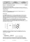
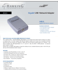
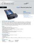
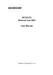
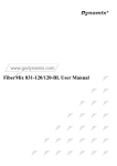
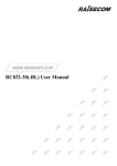
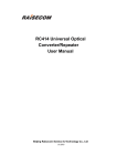
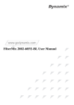
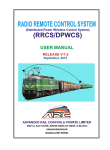
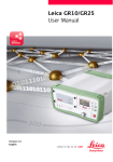
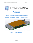
MVB BASED GRAPHICAL DRIVER DISPLAY 10.4 INCH SIZE FOR WAG9/WAP7/WAP5 CLASS LOCOMOTIVES ARC/DDU/V2 USER MANUAL ADVANCED RAIL CONTROLS PRIVATE LIMITED #59/1-2, II FLOOR (ABOVE BANK OF INDIA) G-BLOCK, SAHAKARANAGAR BANGALORE-560 092 JUNE 29, 2012 RELEASE 1.0 1/32 1.0 SCOPE This document describes the technical details of Graphic Driver Display Unit (DDU) used in 3-Phase Electric Locomotives of WAP5, WAP7, WAG9 & WAG9H classes being operated by Indian Railways. The DDU is a man machine interface device able to communicate with locomotive control system through MVB. The LED backlit 10.4” SVGA LCD screen provides better readability even during daylight conditions, thanks to brightness control. The DDU has various pre-defined screens which can be used for investigative monitoring. This Driver Display will work with the following versions (or above) of the locomotive software. It will not work with a lower version of locomotive software. Locomotive Type 2.0 Software Version WAP5 1103 WAP7 2103 WAG9 3103 WAG9H 4103 KEY DESIGN FEATURES The key design features incorporated in this DDU are listed below. SL No Features 1 LCD Display Size Values/Conformance 10.4 inch 2 Overall outer dimensions 316x214x108 mm 3 Brightness Control Available 4 Multiple Screen selection Available 5 6 Pre-loaded GIS information of Indian Railway Routes with route mapping application MVB Connectivity 7 RS422 Connectivity to DDA Available 8 PIXY Screen Zooming Available 9 USB Interface Available 10 Interface for external GPS Receiver Available 11 Ingress Protection 12 13 Cooling Keypads 14 Type of Keys 15 LCD screen resolution 16 LCD screen temperature range 17 Normative Standard Conforming Will be available in future Available Totally enclosed (IP65) External Fan with chassis cooling Function Menu Keys & PIXY screen keys arranged in separate groups High reliability tactile switches totally sealed using custom made silicon keypad 800x600 -30 to +85 degree C IEC-60571 2/32 3.0 MECHANICAL DESIGN The driver display is made out of Aluminium material and exterior is hard anodised black. The special function keys and PIXY screen keys are located on the right side of the facia. The USB interface is provided on the right side top, just above the special function key pad. The rear side of the driver display uses a milled structure with in-built heat sink for chassis cooling. Over the heat sink on the rear side houses a cooling fan (12V DC). The heat generated internally by the heat producing elements like the DC-DC converters and processor is directly transferred to the chassis. The heat generated by other small components is transferred to the chassis indirectly through convection using internal circulating fan. The external fan REAR VIEW HEAT SINK 1 2 COOLING FAN 3 4 5 6 mounted on the heat sink removes the heat from the chassis and maintains the temperature rise under control. All the field interface connectors are terminated on the rear plate on the left side as shown in Figure above. 3/32 SL No Interface Details Connector Type 1 Key Board PS2 Female (only for service engineer) 2 DDA (1/2) RS422 9 Pin Sub-D Female 3 MVB 10 Pin Circular Male (ITT KPSE00F12-10P) 4 External GPS 10 Pin Circular Female (ITT KPSE00F12-10S) 5 External Fan Supply 12V DC 3 Pin Circular Female (ITT KPSE00F12-3S) 6 Power Supply 110V DC 3 Pin Circular Male (ITT KPSE00F12-3P) The equipment can be directly mounted on the C-Panel using screws and the fully assembled C-Panel can be mounted on the driver desk. The mechanical dimensional drawings and mounting instructions are given at the end. FUNCTION KEY PAD USB ESC HOME MENU 10.4 INCH TFT LCD DISPLAY HOME PIXY KEY PAD CLEAR + - 4.0 Operator Controls The Driver Display has two sets of keypads positioned in different clusters. One set is known as “PIXY” display control key pad & another is known as “Function” keypad. The PIXY control keypad has 8 keys and provides exactly the same control as being done in the old type of 4x40 text display. The “Function” keypad has 6 keys, each assigned to a separate function. 4/32 4.01 PIXY Display Control The pixy display control keypad has 08 tactile keys of rugged type. The keys are protected from direct ingress of dust and moisture using a silicon rubber mould. As the rubber protective membrane is very soft, care must be taken to avoid use with sharp materials. The keys are suitable for operation by fingers. The function assigned to each key is given below. Clear Screen Clear Home ↑ Increase Brightness + ↓ Decrease Brightness - ↵ Invokes root menu Up Arrow Down Arrow Enter 4.02 Function Keys The function keys are 06 in number and are used for invoking special functions and screens as detailed below. ESC ↑ Up Arrow Default Screen HOME ↓ Down Arrow Screen Select MENU ↵ Previous Screen 5.0 Enter Screens The Driver display has pre-defined dedicated screens in order to monitor real time process variables pertaining to a particular section or sub-system of the locomotive. However, such screens are meant for online monitoring by technical staff whenever required. The locomotive driver, however, needs to 5/32 view the default screen only most of the times. The screens have been designed to take care of the specification requirement. The details of the screens are explained below. FLG1: 596 SLG1:1099 ALG1: 3212 O/C E/F PRIMARY E/F POWER E/F AUXILIARY 18:20:13 CONTROL Input kW 1 26/01/2012 FLG2: 596 SLG2:1099 ALG2: 3212 2 SS01 SS02 SS03 SS04 SS05 SS06 SS07 SS08 SS09 SS10 SS11 SS12 SS13 SS14 SS15 SS16 SS17 SS18 SS19 SS20 125.4 WAG9 31236 FREQ Hz PANTO W TE/BE X 600 51.2 VCB 30 Vcat 300 Ipri BPCS 80 400 200 200 120 140 40 20 20 100 0 -200 100 60 10 160 0 180 12.23 km/h 50 LSP -400 BATTERY 0 -600 25 kN 28 0 5.00 kV ANTISPIN LOCO 50.0 A BC MR BP 110.23V APPLIED < 6.4 KG 5.02 KG Main menu: Loco 31234 > 1: Vehicle Diagnostics 2: Information train bus 3: Process information EMERGENCY VIGILANCE PARKING AUTO The design philosophy followed is such that all the critical process variables and PIXY screen which are needed to be monitored always by the driver has been provided in a permanent screen area and it will always be available irrespective of any pre-defined screen selected. In any screen, the changing portion is a small area in the space of the speedometer dial of the default screen. This is because, locomotive speed can be monitored through other means also (example: standalone speedometer or the speed in the loco speed available on PIXY screen). 5.01 Default Screen (Screen 1) The driver normally uses the default screen while driving, even though, he can navigate to any other investigative screens, if required. This screen is divided into various sections. The top left portion gives the status of protective relays. When acted, the colour changes to red. Under normal conditions, the colour is not highlighted and gives a gray colour. The middle top provides a window in which processor node numbers are displayed (FLG, SLG & ALG). Right top corner displays current date and time. Please note that the date and time shown are from the driver display 6/32 processor RTC. Incase loco time is needed, the same can be viewed in the PIXY window. The first graphic mimic in the second row shows the loco type and loco number at bottom, the active cab and the direction selected. The active cab is indicated by a small green dot and the arrow indicates the direction selected. The second graphic mimic displays the status of pantograph. A block arrow is used to represent the pantograph. When both the pantographs are down, the arrow looks down in gray colour. When any one panto is raised, the arrow points upwards with green colour. The VCB is represented by three line segments. The notation used is similar to the one used for opening and closing the VCB at OHE neutral sections. When the VCB is OFF, the upper and lower line segments are vertical, middle segment is horizontal and the colour is gray. When the VCB is closed, all the three line segments becomes vertical with green colour. Right of the VCB mimic is the area for displaying input power and line frequency. Input power displays the instantaneous power at pantograph, calculated by ALG in kW. The Line frequency is also measured by ALG in Hz. In the second row right side is the sub-system status. There are 19 subsystems in three phase locomotive. The sub-system 20 does not exist and is retained for getting symmetry of the screen but always remain in gray colour. If a sub-system is isolated, the colour will change to red. A healthy sub-system will be in green colour. For getting the name of the sub-system, Screen-2 can be activated. The third row is split into two vertical halves. The left portion has three vertical meters viz. TE/BE, Catenary Voltage & Primary Current. The TE/BE meter provides demand (W) set on left side. Actual (X) value realised is shown on the right side, which is a very good scale for comparison. The actual numerical value appears at the bottom. Please note that during bad track conditions, Demand (W) and Actual (X) can vary widely,especially during wheel slip conditions. The catenary voltmeter shows the catenary voltage (0 to 30kV normal reading). During over voltage and under voltage, the colour of the numerical reading changes to red. The primary current is shown in a 0 to 300A scale. The right half side of row 3 of the display is again split into two horizontal portions. The upper portion shows the speedometer mimic. The driver display reads the loco type from the MVB (WAG9/WAG9H/WAP7/WAP5) and accordingly adjusts the maximum speed limit range. The portion upto the maximum limit is shown in green colour and above the speed limit is shown in red colour. In WAG9/9H locomotives, the speed limit is 100 km/h and in WAP5/WAP7, the speed limit is 130 km/h. These figures are automatically adjusted based on the loco type. The numerical value of the speed in km/h is displayed at the bottom. 7/32 In the right side of the speedometer dial area, an indication is given for the constant speed operation. When driver presses the constant speed button BPCS, this indication turns green. When not in constant speed mode, the colour is gray. Within the same speedometer dial area right bottom corner, an indication for wheel slip (LSP) is provided. When there is wheel slip, this indication turns orange, otherwise, the colour is gray. Below the speedometer dial, four process variables are displayed viz. battery, BC, MR & BP. The battery voltage, when normal, will be shown in green. When the value goes below 86V, it will be shown in red. The brake cylinder pressure (BC) is shown in boolean form as ʻappliedʼ or ʻreleasedʼ depending upon the brake cylinder pressure. Similarly, MR pressure is also shown in boolean form. When MR pressure builds up above 6.4 kg/sq.cm, it is shown in green and when it goes below 6.4 kg/sq.cm, it is shown as red. For brake pressure, absolute analogue value is displayed, which varies from 0 to around 5.6 kg/sq.cm. When the value is above 4.8 kg/sq.cm, it means that the brakes are in released condition and the value will be shown in green. Below 4.8 kg/sq.cm, it is a brake applied condition and hence will be shown in red. The bottom most row has two portions, the left half shows brake status and the right half is dedicated for the PIXY terminal display. The loco brake status is shown as ʻLOCOʼ. When the loco brake is not applied, the mimic will be shown in gray colour and arrows pointing away. When loco brake is applied, it turns red and arrows pointing inwards. When anti slip (anti spin) brakes comes into action, the text ʻANTISPINʼ above the loco brake mimic will light up in red. The train brake application is represented by a mimic named ʻAUTOʼ which represents auto brake. When not applied, the arrows are gray and pointing away. When brakes are applied, the colour turns red and arrows pointing inwards. During emergency brake application, the corresponding arrows turns red and points inwards. In release condition, the arrows are gray and pointing outwards. ZOOM FUNCTION IN PIXY SCREEN While in default screen, when <enter> key is pressed in the function key pad (upper group of key pad), the PIXY screen will zoom in to full screen. In the zoomed condition or in the normal condition, all the functionalities are available through the PIXY key pad (bottom group of keys). Pressing <HOME> in the upper group keypad will restore the original screen. 8/32 NAVIGATION TO OTHER SCREENS While in default screen (screen-1), when <menu> button is pressed in the upper group keypad, a new screen will appear in the place of speedometer dial. The speedometer portion has been sacrificed here to give a menu of predefined screens that can be viewed. Please note that the Driver will normally drive using default screen only. Other sub-screens are needed for investigative purpose. There are 14 pre-defined screens presently catered. LIST OF SCREENS In the above condition, if <HOME> button is pressed, default screen will appear. When the list of screen is displayed, one can navigate to a particular screen by pressing <UP> or <DOWN> arrow keys of the upper group of key pads. After selecting the particular screen, when <ENTER> is pressed, the contents of the selected screen will get displayed. Again by pressing <ESC> will take the menu one level up till the list of screens. Thereafter, by pressing <HOME> in upper group, default screen will appear. Even from any submenu, when <HOME> is pressed in the upper group, default menu will appear. FLG1: 596 SLG1:1099 ALG1: 3212 O/C E/F PRIMARY E/F POWER E/F AUXILIARY 18:20:13 CONTROL Input kW 1 2 SS01 SS02 SS03 SS04 SS05 SS06 SS07 SS08 SS09 SS10 SS11 SS12 SS13 SS14 SS15 SS16 SS17 SS18 SS19 SS20 125.4 WAG9 31236 FREQ Hz PANTO W TE/BE X 600 51.2 VCB 30 Vcat 300 Ipri SCREENS 1.SUB-SYSTEM STATUS 400 200 3.TRACTION CONVERTER 10.PRESSURES 20 100 0 -200 10 50 -400 4.AUX. CONVERTER 11.ROUTE MAP 5.TRACTION MOTOR 12.SPEED RESTRICTON 6.AUX. SYSTEM 13.DRIVER DETAILS 7.BRAKING SYSTEM 14.I/O SIGNALS BATTERY 0 -600 kN 28 0 5.00 kV ANTISPIN LOCO 8.ENERGY MONITORING 2.HIGH VOLTAGE CIRCUIT 9.TEMPERATURES 200 25 26/01/2012 FLG2: 596 SLG2:1099 ALG2: 3212 50.0 A BC MR BP 110.23V APPLIED < 6.4 KG 5.02 KG Main menu: Loco 31234 > 1: Vehicle Diagnostics 2: Information train bus 3: Process information EMERGENCY VIGILANCE PARKING AUTO 9/32 SCREEN 2.1 : SUB-SYSTEM STATUS FLG1: 596 SLG1:1099 ALG1: 3212 O/C E/F PRIMARY E/F POWER E/F AUXILIARY 18:20:13 CONTROL Input kW 1 2 SS01 SS02 SS03 SS04 SS05 SS06 SS07 SS08 SS09 SS10 SS11 SS12 SS13 SS14 SS15 SS16 SS17 SS18 SS19 SS20 125.4 WAG9 31236 FREQ Hz PANTO W TE/BE X 600 51.2 VCB 30 Vcat 300 Ipri SUB-SYSTEM STATUS SS01 SS02 SS03 HV Bogie 1 Bogie 2 400 200 200 20 100 0 -200 10 kN 28 0 5.00 kV ANTISPIN LOCO 50.0 A SS05 Hotel SS07 BUR2 SS08 BUR3 SS09 SS10 Battery Braking SS11 HBB1 SS12 HBB2 SS13 CAB1 SS14 CAB2 BATTERY 0 -600 SS04 Filter SS06 BUR1 SS16 SS17 SPEED FLG1 50 -400 25 26/01/2012 FLG2: 596 SLG2:1099 ALG2: 3212 BC SS15 Fire SS18 SS20 SS19 FLG2 Train Bus Spare MR BP 110.23V APPLIED < 6.4 KG 5.02 KG VIGILANCE PARKING AUTO Main menu: Loco 31234 > 1: Vehicle Diagnostics 2: Information train bus EMERGENCY 3: Process information In the sub-system status menu, the names of the sub-systems are listed. To navigate to default screen, press <HOME>. To navigate to list of screens, press <ESC>. The isolated sub-system will be shown in red. SCREEN 2.2: HIGH VOLTAGE CIRCUIT In the HIGH VOLTAGE CIRCUIT screen, Harmonic Filter status and Hotel Load status are additionally provided. Other variables are already available in the default screen. Hotel Load facility is available only in WAP7 & WAP5 class of locomotives. 10/32 FLG1: 596 SLG1:1099 ALG1: 3212 O/C E/F PRIMARY E/F POWER E/F AUXILIARY 18:20:13 CONTROL Input kW 1 26/01/2012 FLG2: 596 SLG2:1099 ALG2: 3212 2 SS01 SS02 SS03 SS04 SS05 SS06 SS07 SS08 SS09 SS10 SS11 SS12 SS13 SS14 SS15 SS16 SS17 SS18 SS19 SS20 125.4 FREQ Hz WAG9 31236 PANTO 51.2 VCB W TE/BE X 30 600 Vcat 300 Ipri HIGH VOLTAGE CIRCUIT Panto Up VCB Status Hotel Load Catenary Voltage 400 200 200 Primary Current 20 10 50 BATTERY -400 0 -600 25 kN 50.0 A ANTISPIN LOCO BC 110.23 APPLIED 0 5.00 kV 28 50.0A Line Frequency input Power kW Primary Over Current Filter Earth fault Power Circuit 100 0 -200 OFF OFF OFF 5.0kV 51.2 Hz 125.4kW OFF OFF OFF MR BP < 6.4 5.02 Kg/cm2 Volts Kg/cm2 VIGILANCE PARKING Main menu: Loco 31234 > 1: Vehicle Diagnostics 2: Information train bus EMERGENCY 3: Process information AUTO SCREEN 2.3 : TRACTION CONVERTER FLG1: 596 SLG1:1099 ALG1: 3212 O/C E/F PRIMARY E/F POWER E/F AUXILIARY 2 SS01 SS02 SS03 SS04 SS05 SS06 SS07 SS08 SS09 SS10 SS11 SS12 SS13 SS14 SS15 SS16 SS17 SS18 SS19 SS20 125.4 WAG9 31236 FREQ Hz PANTO W TE/BE X 600 51.2 VCB 30 Vcat 300 Ipri 200 200 INPUT CONTACTOR 20 OIL PRESSURE OIL TEMPERATURE INPUT POWER VENTILLATION LEVEL 100 0 -200 10 BATTERY 50 -400 28 0 5.00 kV ANTISPIN LOCO BC 110.23 APPLIED 0 -600 kN TRACTION CONVERTER FLG NODE SLG NODE ALG NODE PRE-CHARGE CONTACTOR 400 25 18:20:13 CONTROL Input kW 1 26/01/2012 FLG2: 596 SLG2:1099 ALG2: 3212 Volts MR BP < 6.4 5.02 Kg/cm2 Kg/cm2 50.0 A VIGILANCE PARKING AUTO Main menu: Loco 31234 > 1: Vehicle Diagnostics 2: Information train bus EMERGENCY 3: Process information 11/32 In TRACTION CONVERTER screen, converter related parameters are displayed. The screen is split into two columns, one for each traction converter. The process variables displayed include pre-charge & input contactor status, oil pressure & temperatures, input power & ventilation level. Other displayed parameters are already available on default screen. SCREEN 2.4 : AUXILIARY CONVERTER FLG1: 596 SLG1:1099 ALG1: 3212 O/C E/F PRIMARY E/F POWER E/F AUXILIARY 2 SS01 SS02 SS03 SS04 SS05 SS06 SS07 SS08 SS09 SS10 SS11 SS12 SS13 SS14 SS15 SS16 SS17 SS18 SS19 SS20 125.4 WAG9 31236 FREQ Hz PANTO W TE/BE X 600 VCB 30 Vcat 51.2 300 Ipri 200 200 OUTPUT FREQUENCY 100 0 GROUPING CONTACTORS BATTERY 10 50 kN MR 54/5 BP < 6.4 5.02 Kg/cm2 Kg/cm2 50.0 A VIGILANCE PARKING 54/4 0 5.00 kV ANTISPIN LOCO BC Volts 0 28 54/1 54/2 54/3 110.23 APPLIED -400 -600 OFF OFF OUTPUT VOLTAGE 20 -200 AUXILIARY CONVERTER AUXILIARY VOLTAGE AUXILIARY CURRENT DC LINK VOLTAGE DC LINK CURRENT 400 25 18:20:13 CONTROL Input kW 1 26/01/2012 FLG2: 596 SLG2:1099 ALG2: 3212 AUTO Main menu: > 1: Vehicle Diagnostics 2: Information train bus EMERGENCY 3: Process information Loco 31234 The Auxiliary Converter screen provides very vital process variable display about the BUR, which will help in easy trouble shooting. The variables include Auxiliary winding voltage, Total current in the auxiliary winding, dc link voltage & dc link current of each BUR, output voltage and output frequency. Please note that there is no direct signal available for the output voltage whereas the displayed value is calculated from dc link voltage and output frequency considering constant v/f relation. The screen also provides the status of BUR grouping contactors. SCREEN 2.5 : TRACTION MOTOR The traction motor screen is also vertically split into two columns, one for 3 motors belonging to one bogie. The relevant process variables like input contactor status, dc link voltage, ventilation level, converter input power, wheel slip status, speed of each traction motor reported from speed sensor 12/32 and temperature of each traction motor reported by the temperature sensor are displayed. FLG1: 596 SLG1:1099 ALG1: 3212 O/C E/F PRIMARY E/F POWER E/F AUXILIARY 18:20:13 CONTROL Input kW 1 2 SS01 SS02 SS03 SS04 SS05 SS06 SS07 SS08 SS09 SS10 SS11 SS12 SS13 SS14 SS15 SS16 SS17 SS18 SS19 SS20 125.4 WAG9 31236 FREQ Hz PANTO W TE/BE X 600 VCB 30 Vcat 51.2 300 Ipri 200 200 TRACTION MOTOR INPUT CONTACTOR DC LINK VOLTAGE VENTILLATION LEVEL SR INPUT POWER kW 400 WHEEL SLIP 20 TM SPEED km/h TM TEMPERATURE DEG C 100 0 BATTERY -200 10 Volts 0 -600 kN 28 BP < 6.4 5.02 Kg/cm2 Kg/cm2 50.0 A VIGILANCE PARKING MR 0 5.00 kV ANTISPIN LOCO BC 110.23 APPLIED 50 -400 25 26/01/2012 FLG2: 596 SLG2:1099 ALG2: 3212 AUTO Main menu: > 1: Vehicle Diagnostics 2: Information train bus EMERGENCY 3: Process information Loco 31234 SCREEN 2.6 : AUXILIARY SYSTEM The auxiliary system screen essentially displays the status of various auxiliary machines, as to whether these are OFF or ON. It also indicates the BUR status and BUR input volatge. The auxiliary machines considered are Compressors (1,2), Oil Cooling Blowers (1,2), Oil Pump Converter (1,2), Oil Pump Transformer (1,2), Traction Motor Blower (1,2) & Machine Room Blower (1,2). 13/32 FLG1: 596 SLG1:1099 ALG1: 3212 O/C E/F PRIMARY E/F POWER E/F AUXILIARY 18:20:13 CONTROL Input kW 1 26/01/2012 FLG2: 596 SLG2:1099 ALG2: 3212 2 SS01 SS02 SS03 SS04 SS05 SS06 SS07 SS08 SS09 SS10 SS11 SS12 SS13 SS14 SS15 SS16 SS17 SS18 SS19 SS20 125.4 FREQ Hz WAG9 31236 PANTO VCB W TE/BE X 30 600 51.2 Vcat 300 Ipri AUXILIARY SYSTEM AUXILIARY VOLTAGE BUR 1,2,3 STATUS COMPRESSOR 1,2 OCB 1,2 SR OIL PUMP 1,2 400 200 200 20 TFP OIL PUMP 1,2 TM BLOWER 1,2 MR BLOWER 1,2 100 0 BATTERY -200 10 50 BC MR 110.23 APPLIED -400 BP < 6.4 Volts 0 -600 25 kN 50.0 A ANTISPIN LOCO VIGILANCE PARKING Kg/cm2 0 5.00 kV 28 5.02 Kg/cm2 Main menu: > 1: Vehicle Diagnostics 2: Information train bus EMERGENCY 3: Process information AUTO Loco 31234 SCREEN 2.7 : BRAKING SYSTEM FLG1: 596 SLG1:1099 ALG1: 3212 O/C E/F PRIMARY E/F POWER E/F AUXILIARY 18:20:13 CONTROL Input kW 1 2 SS01 SS02 SS03 SS04 SS05 SS06 SS07 SS08 SS09 SS10 SS11 SS12 SS13 SS14 SS15 SS16 SS17 SS18 SS19 SS20 125.4 WAG9 31236 FREQ Hz PANTO W TE/BE X 600 VCB 30 Vcat 51.2 300 Ipri 200 200 20 REGENERATED POWER kW REGENERATED ENERGY kWh COMPRESSOR 1,2 100 0 BRAKING SYSTEM SPEED MASTER CONTROLLER BE DEMAND kN BE ACTUAL kN PNEUMATIC BRAKE DEMAND 400 BATTERY -200 10 50 BC 110.23 APPLIED -400 Volts 0 -600 25 26/01/2012 FLG2: 596 SLG2:1099 ALG2: 3212 kN 28 < 6.4 5.02 Kg/cm2 Kg/cm2 50.0 A VIGILANCE PARKING BP 0 5.00 kV ANTISPIN LOCO MR AUTO Main menu: > 1: Vehicle Diagnostics 2: Information train bus EMERGENCY 3: Process information Loco 31234 14/32 The braking system screen displays the process variables related to braking, which include locomotive speed, master controller position (traction/braking region), BE demand and BE Actual, Pneumatic Brake Effort demand (when regeneration fails), regenerated power & energy as well as status of compressor. SCREEN 2.8 : ENERGY MONITORING FLG1: 596 SLG1:1099 ALG1: 3212 O/C E/F PRIMARY E/F POWER E/F AUXILIARY 18:20:13 CONTROL Input kW 1 2 SS01 SS02 SS03 SS04 SS05 SS06 SS07 SS08 SS09 SS10 SS11 SS12 SS13 SS14 SS15 SS16 SS17 SS18 SS19 SS20 125.4 WAG9 31236 FREQ Hz PANTO W TE/BE X 600 VCB 30 Vcat 51.2 300 Ipri ENERGY MONITORING ENERGY CONSUMED CUMULATIVE 400 ENERGY REGENERATED CUMULATIVE 200 200 ENERGY CONSUMED TRIP ENERGY REGENERATED TRIP 20 REGENERATION RATIO CUMULATIVE 100 0 REGENERATION RATIO TRIP BATTERY -200 10 50 BC 110.23 APPLIED -400 Volts 0 -600 25 26/01/2012 FLG2: 596 SLG2:1099 ALG2: 3212 kN 28 < 6.4 5.02 Kg/cm2 Kg/cm2 50.0 A VIGILANCE PARKING BP 0 5.00 kV ANTISPIN LOCO MR AUTO Main menu: > 1: Vehicle Diagnostics 2: Information train bus EMERGENCY 3: Process information Loco 31234 The screen for energy monitoring displays the energy consumed and regenerated. The cumulative value is the one taken from the NVRAM of DIA computer, which is available on MVB. The trip energy is calculated by the driver display itself from the time of switching ON. This value is not saved in any memory and will vanish once the locomotive is OFF. Trip energy can be used for comparison of driver performance under identical conditions of operation. The regeneration ratio (energy regenerated/energy consumed) is calculated by the driver display and displayed. This factor also provides a measure of the efficiency of regeneration and is a good comparison tool. 15/32 SCREEN 2.9 : TEMPERATURES FLG1: 596 SLG1:1099 ALG1: 3212 O/C E/F PRIMARY E/F POWER E/F AUXILIARY 18:20:13 CONTROL Input kW 1 2 SS01 SS02 SS03 SS04 SS05 SS06 SS07 SS08 SS09 SS10 SS11 SS12 SS13 SS14 SS15 SS16 SS17 SS18 SS19 SS20 125.4 WAG9 31236 FREQ Hz PANTO W TE/BE X 600 VCB 30 Vcat 51.2 300 Ipri TEMPERATURES TFP OIL 1,2 DEG C 400 SR OIL 1, 2 DEG C 200 200 TM1 1,2 DEG C TM2 1,2 DEG C 20 TM3 1,2 DEG C 100 0 INPUT POWER 1,2 kW BATTERY -200 10 50 BC 110.23 APPLIED -400 Volts 0 -600 25 26/01/2012 FLG2: 596 SLG2:1099 ALG2: 3212 kN 28 < 6.4 5.02 Kg/cm2 Kg/cm2 50.0 A VIGILANCE PARKING BP 0 5.00 kV ANTISPIN LOCO MR AUTO Main menu: > 1: Vehicle Diagnostics 2: Information train bus EMERGENCY 3: Process information Loco 31234 The temperature screen provides various temperatures recorded by sensors and the same can be compared with the converter input power. The temperatures of transformer oil, traction converter oil and traction motors are displayed alongwith converter input power for each bogie. SCREEN 2.10 : PRESSURES This screen shows the pressure variables. It include Transformer oil pressure, converter oil pressure, MR pressure, BP pressure and status of BC1 & BC2. 16/32 FLG1: 596 SLG1:1099 ALG1: 3212 O/C E/F PRIMARY E/F POWER E/F AUXILIARY 18:20:13 CONTROL Input kW 1 2 SS01 SS02 SS03 SS04 SS05 SS06 SS07 SS08 SS09 SS10 SS11 SS12 SS13 SS14 SS15 SS16 SS17 SS18 SS19 SS20 125.4 WAG9 31236 FREQ Hz PANTO W TE/BE X 600 VCB 30 Vcat 51.2 300 Ipri PRESSURES TFP OIL 1,2 bar 400 SR OIL 1, 2 bar 200 200 MR PRESSURE > 6.4 BP PRESSURE KG/SQ CM 20 BC1 PRESSURE 100 0 BC2 PRESSURE BATTERY -200 10 50 BC 110.23 APPLIED -400 MR 0 -600 kN ANTISPIN LOCO Kg/cm2 50.0 A VIGILANCE PARKING 5.02 Kg/cm2 0 5.00 kV 28 BP < 6.4 Volts 25 26/01/2012 FLG2: 596 SLG2:1099 ALG2: 3212 AUTO Main menu: > 1: Vehicle Diagnostics 2: Information train bus EMERGENCY 3: Process information Loco 31234 SCREEN 2.11 : ROUTE MAP KM CHAINAGE:............... DIST TO NEXT STATION:............... MATUNGA DIST TO NEXT NEUTRAL SECTION:.............. DIST TO NEXT SPEED RESTRICTION:............. MAHIM (NOT IMPLEMENTED PRESENTLY) BANDRA The route map is a futuristic provision given as per the specification. In the driver display, already a serial interface is provided to connect an external GPS receiver for getting the GPS co-ordinates of the location. Based on the received GPS latitude and longitude, a map can be generated using the 17/32 SIMRAN data base. This feature would be available in the future versions, when an external GPS receiver is connected and corresponding software is loaded. For full fledged implementation railway has to provide database of SIMRAN and that of neutral section locations & permanent speed restriction locations. SCREEN 2.12 : PERMANENT SPEED RESTRICTION KM CHAINAGE FROM TO PERMITTED SPEED (NOT IMPLEMENTED PRESENTLY) This function is futuristic and not implemented presently. For full fledged implementation, railways have to device a mechanism to feed the en-route permanent speed restrictions into the driver display. It would also require logistics for transferring the speed restrictions en-route from a base station to a moving train. Presently, a USB interface is provided for reading in such data. When railway is ready with a workable mechanism, this function can be activated. However, this also needs connecting a GPS receiver. SCREEN 2.13 : DRIVER / JOURNEY DETAILS This screen is not made active, and is reserved for future implementations. The full-fledged implementation would be available in future versions through an authentication device like a USB stick. The data has to be entered by the driver before the start of the journey. It is not mandatory to enter the data for the functioning of the equipment. This feature can help in comparison of driving performance, specific energy consumption etc. 18/32 DRIVER / JOURNEY DETAILS DRIVER NAME / ID : (input) TRAIN NAME : (input) TRAIN LOAD TONS : (input) ORIGIN CODE : (input) DESTINATION CODE : (input) SIGN IN TIME/DATE : (input) TRIP KM : (calculated by system) SPECIFIC ENERGY : (calculated by system) SCREEN 2.14 : INPUT/OUTPUT SIGNALS The physical input/output signals, both analog and digital, can be viewed using this multi-level screen. In this screen, the description of the signal, name used in FUPLA and the location of the signals and the actual value can be viewed (channel+slot+connector+pin number eg: 12/EA05 : means channel-12, E slot, A connector, pin-5). These screens will be quite useful for troubleshooting. INPUT/OUTPUT SIGNALS ANALOG SIGNALS DIGITAL SIGNALS 19/32 SCREEN 2.14.1 : ANALOG SIGNALS ANALOG SIGNALS FLG-1 FLG-2 SLG-1 SLG-2 SCREEN 2.14.1.1 ANALOG SIGNALS – FLG1 FLG1 INPUT SIGNALS SIGNAL DESCRIPTION Angle Transmitter Pressure Auto Brake FLG1 OUTPUT SIGNALS TE/BE Meter Bogie-1 TE/BE Meter Bogie-2 SIGNAL NAME IN FUPLA CHANNEL/ SLOT:CONNECTOR:PIN 0101-XAngTrans 0101-XPrAutoBkLn 12/EA05 6/EC01 0201-XMeterT/B1 0201-XMeterT/B2 2/EG01 4/EI01 SCREEN 2.14.1.2 ANALOG SIGNALS – FLG2 FLG2 INPUT SIGNALS SIGNAL DESCRIPTION Angle Transmitter Pressure Auto Brake FLG2 OUTPUT SIGNALS TE /BE Meter Bogie-1 TE/BE Meter Bogie-2 Pneumatic Brake Demand SIGNAL NAME IN FUPLA CHANNEL/ SLOT:CONNECTOR:PIN 0101-XAngTrans 0101-XPrAutoBkLn 12/EA05 6/EC01 0201-XMeterT/B1 0201-XMeterT/B2 0201-WPnBEdem 2/EG01 4/EI01 1/EC05 20/32 SCREEN 2.14.1.3 ANALOG SIGNALS – SLG1 (INPUTS) SLG1 ANALOG SIGNALS SIGNAL DESCRIPTION Primary Current Total BUR Current Filter Current Pressure TFP Oil Pressure SR Oil Temperature 1 TFP Oil Temperature 2 TFP Oil Temperature1 SR Oil Temperature2 SR Oil TM1 Temperature (sensor 1) TM1 Temperature (sensor 2) TM2 Temperature (sensor 1) TM2 Temperature (sensor 2) TM3 Temperature (sensor 1) TM3 Temperature (sensor 2) SIGNAL NAME IN FUPLA CHANNEL/SLOT:CONNECTOR:PIN 0104-XAIpr 0104-XAIBUR 0104-XAIFilts 0106-XADruckTR 0106-XADruckSR 0106-XATmp1OelTR 0106-XATmp2OelTR 0106-XATmp1OelSR 0106-XATmp2OelSR 0106-XATmp1Mot1 0106-XATmp2Mot1 0106-XATmp1Mot2 0106-XATmp2Mot2 0106-XATmp1Mot3 0106-XATmp2Mot3 1/AA06 2/AC06 3/AE06 8/AI06 12/DK07 11/DI05:09 10/DI06:01 11/DG05:09 10/DG06:01 7/DA05:09 6/DA06:01 9/DC05:09 8/DC06:01 7/DE05:09 6/DE06:01 SCREEN 2.14.1.4 ANALOG SIGNALS – SLG2 SLG2 ANALOG SIGNALS SIGNAL DESCRIPTION Primary Current Total BUR Current Filter Current Pressure TFP Oil Pressure SR Oil Temperature 1 TFP Oil Temperature 2 TFP Oil Temperature1 SR Oil Temperature2 SR Oil TM1 Temperature (sensor 1) TM1 Temperature (sensor 2) TM2 Temperature (sensor 1) TM2 Temperature (sensor 2) TM3 Temperature (sensor 1) TM3 Temperature (sensor 2) SIGNAL NAME CHANNEL/SLOT:CONNECTOR:PIN 0104-XAIpr 0104-XAIBUR 0104-XAIFilt 0106-XADruckTR 0106-XADruckSR 0106-XATmp1OelTR 0106-XATmp2OelTR 0106-XATmp1OelSR 0106-XATmp2OelSR 0106-XATmp1Mot1 0106-XATmp2Mot1 0106-XATmp1Mot2 0106-XATmp2Mot2 0106-XATmp1Mot3 0106-XATmp2Mot3 1/AA06 2/AC/06 3/AE06 8/AI06 12/DK07 11/DI05:09 10/DI06:01 11/DG05:09 10/DG06:01 7/DA05:09 6/DA06:01 9/DC05:09 8/DC06:01 7/DE05:09 6/DE06:01 21/32 SCREEN 2.14.2 DIGITAL SIGNALS DIGITAL SIGNALS HBB1 HBB2 STB1 STB2 SLG1 SLG2 SCREEN 2.14.2.1 DIGITAL SIGNALS HBB1 HBB1 INPUT SIGNALS GROUP 1 GROUP 2 GROUP 1 GROUP 2 OUTPUT SIGNALS SCREEN 2.14.2.1.1 DIGITAL SIGNALS HBB1 INPUT GROUP 1 HBB1 DIGITAL INPUTS GROUP 1 SIGNAL DESCRIPTION Relay Control Electronics ON Emergency Stop MR Blower OK Max TE Limit Banking Operation Compressor ON Compressor Direct Foot Switch Loco Brake Driving Direction Forward Driving Direction Reverse Throttle in Traction Mode Throttle in Braking Zone TE/BE Demand Switch > 1/3 TE/BE Demand Switch > 2/3 Push Button Fault Acknowledge SIGNAL NAME IN FUPLA 0101-MRelMCEOn 0101-LEmgStop 0101-MMRBlowerOk 0101-LMaxTELimit 0101-LSwBankOp 0101-LSwComprOff 0101-LSwComprDir 0101-LFootSwLoBk 0101-LTrvDirFor 0101-LTrvDirRev 0101-LTEDemand 0101-LBEDemand 0101-LT/BDem>1/3 0101-LT/BDem>2/3 0101-LPBFaultAck CHANNEL/ SLOT:CONNECTOR:PIN 2/OA09 3/OA02 4/OA10 5/OA03 6/OA11 7/OA04 8/OA12 9/OD01 10/OD9 11/OD02 12/OD10 13/OD03 14/OD11 15/OD04 16/OD12 22/32 SCREEN 2.14.2.1.2 DIGITAL INPUTS HBB1 GROUP 2 HBB1 DIGITAL INPUTS GROUP 2 SIGNAL DESCRIPTION SIGNAL NAME IN FUPLA CHANNEL/ SLOT:CONNECTOR:PIN Auxiliary Supply Fuse Status MCB Oil Cooling Blower 1 MCB Machine Room Blower 1 MCB Scavenge Blower to MR1 MCB Oil Pump SR1 MCB TFP Pump 1 MCB TM Blower 1 MCB Scavenge to TM Blower 1 Earth Fault in 400/110V AC Circuit Earth Fault in Hotel Load Circuit VCB Status VCB ON Command Earth Fault in Filter Circuit Earth Fault in Control Circuit CoCo Detect BEF Model 0102-MFuseAux 0102-MMCBBloCT1 0102-MMCBBloMR1 0102-MMCBMScBlo1 0102-MMCBPumpC1 0102-MMCBPumpT1 0102-MMCBBloTM1 0102-MMCBTScBlo1 0102-MEFR415/110 0102-MEFRHotel 0102-MAuxConVCB 0102-LVCBOn 0102-MEFRFilter 0102-MEFRContrl 0102-BDetCoCo 0102-MBEFModel 1/QA01 2/QA09 3/QA02 4/QA10 5/QA03 6/QA11 7/QA04 8/QA12 9/QD01 10/QD09 11/QD02 12/QD10 13/QD03 14/QD11 15/QD04 16/QD12 SCREEN 2.14.2.1.3 DIGITAL SIGNALS HBB1 OUTPUT GROUP 1 HBB1 DIGITAL OUTPUTS GROUP 1 SIGNAL DESCRIPTION Fault Indication Lamp Fault Status Lamp Buzzer Black Command Self MCE Contactor Compressor 1 Buzzer Red SIGNAL NAME IN FUPLA 0201-MLampFInd 0201-MLampFault 0201-BBuzzBlack 0201-BSelfMCE 0201-BContCP1 0201-BBuzzRed CHANNEL/ SLOT:CONNECTOR:PIN 1/OG19 2/OG20 8/OG03 12/OJ03 14/OJ09 16/OG14 23/32 SCREEN 2.14.2.1.4 DIGITAL SIGNALS HBB1 OUTPUT GROUP 2 HBB1 DIGITAL OUTPUTS GROUP 2 SIGNAL DESCRIPTION SIGNAL NAME IN FUPLA VCB ON Command (EFDJ) Contactor Self Hold VCB ON Command (MTDJ) Contactor VCB Disable 0202-BVCBOnPulse 0202-BContSelfH 0202-BVCBOn 0202-BVCBDisable CHANNEL/ SLOT:CONNECTOR:PIN 7/QJ06 12/QJ03 13/QJ12 14/QJ09 SCREEN 2.14.2.2 DIGITAL SIGNALS HBB2 SCREEN 2.14.2.2.1 DIGITAL SIGNALS HBB2 INPUT GROUP 1 HBB2 DIGITAL INPUT GROUP 1 SIGNAL DESCRIPTION MCB Compressor 2 Emergency Stop MR Blower OK Max TE Limit Switch Switch Banking Operation Switch Compressor OFF Switch Compressor Direct Foot Switch Loco Brake Direction Forward Direction Reverse Throttle in Traction Mode Throttle in Brake Mode TE/BE Demand > 1/3 Switch TE/BE Demand > 2/3 Switch Push Button Fault Acknowledge SIGNAL NAME IN FUPLA 0101-MMCBCompr2 0101-LEmgStop 0101-MMRBlowerOk 0101-LMaxTELimit 0101-LSwBankOp 0101-LSwComprOff 0101-LSwComprDir 0101-LFootSwLoBk 0101-LTrvDirFor 0101-LTrvDirRev 0101-LTEDemand 0101-LBEDemand 0101-LT/BDem>1/3 0101-LT/BDem>2/3 0101-LPBFaultAck CHANNEL/ SLOT:CONNECTOR:PIN 1/OA01 3/OA02 4/OA10 5/OA03 6/OA11 7/OA04 8/OA12 9/OD01 10/OD09 11/OD02 12/OD10 13/OD03 14/OD11 15/OD04 16/OD12 24/32 SCREEN 2.14.2.2.2 DIGITAL SIGNALS HBB2 INPUT GROUP 2 HBB2 DIGITAL INPUT GROUP 2 SIGNAL DESCRIPTION Pressure Switch Pan1 Pressure Switch Pan2 Pressure Switch Park Brake Brake Electronics OK Cock Brake Control Emergency Brake Out Pressure Switch Loco Brake Pressure Switch Emergency Brake Pressure Switch Air Flow Driver Command Pan Up MR Pressure > 7.5 Bar Fire Alarm Pressure Switch Brake Cylinder 2 Pressure Switch Low MR MR Pressure > 8 bar Pressure Switch Brake Feed Pipe SIGNAL NAME IN FUPLA 0102-MPrSwPan1 0102-MPrSwPan2 0102-MPrSwParkBk 0102-MBrakElecOK 0102-LCockBkCon 0102-LEmgBkOut 0102-MPrSwLocoBk 0102-MPrSwEmgBk 0102-MPrSwAFlow 0102-LPanUp 0102-MPrSw75bar 0102-MFireAlarm 0102-MPrSwBkCyl2 0102-MPrSwLowMR 0102-MPrSw8bar 0102-MPrSwBkFP CHANNEL/ SLOT:CONNECTOR:PIN 1/QA01 2/QA09 3/QA02 4/QA10 5/QA03 6/QA11 7/QA04 8/QA12 9/QD01 10/QD09 11/QD02 12/QD10 13/QD03 14/QD11 15/QD04 16/QD12 SCREEN 2.14.2.2.3 DIGITAL SIGNALS HBB2 OUTPUT GROUP 1 HBB2 DIGITAL OUTPUT GROUP 1 Fault Indication Lamp Fault Status Lamp EP Valve Auto Brake Out Reset Vigilance Penalty Brake Buzzer Black EP Valve Anti Spin 2 Vigilance Reset Vigilance Control Buzzer Red 0201-MLampFInd : 1/OG19 0201-MLampFault : 2/OG20 0201-MLampFault : 4/OJ07 0201-BResVigPeBk : 7/OJ13 0201-BBuzzBlack : 8/OG03 0201-BEPAntSpin2 : 12/OJ03 0201-BVigReset : 13/OJ12 0201-BVigControl : 14/OJ09 0201-BBuzzRed : 16/OG14 25/32 SCREEN 2.14.2.2.4 DIGITAL SIGNALS HBB2 OUTPUT GROUP 2 HBB2 DIGITAL OUTPUT GROUP 2 SIGNAL DESCRIPTION EP Valve Release Parking Brake EP Valve Compressor Unload EP Valve sanding 1-3 EP Valve Panto1 EP Valve Sanding 2-4 Contactor Compressor 2 Panto Disable EP Valve Parking Brake EP Valve Loco Brake Out SIGNAL NAME IN FUPLA 0202-BEPRelPBk 0202-BEPCPUnload 0202-BEPSand13 0202-BEPPan1 0202-BEPSand24 0202-BContCompr2 0202-BPanDisable 0202-BEPApplyPBk 0202-BEPLBkOut CHANNEL/ SLOT:CONNECTOR:PIN 6/QG18 8/QG03 9/QG17 10/QG23 11/QG12 12/QJ10 14/QJ09 15/QG22 16/QG14 SCREEN 2.14.2.3 DIGITAL SIGNALS STB1 SCREEN 2.14.2.3.1 DIGITAL SIGNALS STB1 INPUT GROUP 1 STB1 DIGITAL INPUT GROUP 1 SIGNAL DESCRIPTION MCB Status Compressor 1 Apply Parking Brake Hotel Load Contactor Status Cab Activating Switch in Driving Cab Activating Switch in Cooling Constant Speed Button Hotel Load Off Foot Switch Sanding Direction Forward Direction Reverse SIGNAL NAME IN FUPLA CHANNEL/ SLOT:CONNECTOR:PIN 0101-MMCBCompr1 0101-LParkBrake 0101-LHotelOn 0101-LActKSwD 0101-LActKSwC 0101-LConstSpeed 0101-LHotelOff 0101-LFootSwSand 0101-LTrvDirFor 0101-LTrvDirRev 1/JA01 2/JA09 4/JA10 5/JA03 6/JA11 7/JA04 8/JA12 9/JD01 10/JD09 11/JD02 26/32 SCREEN 2.14.2.3.2 DIGITAL SIGNALS STB1 INPUT GROUP 2 STB1 DIGITAL INPUT GROUP 2 SIGNAL DESCRIPTION Temp Relay Control Electronics Cutout Switch Bogie-1 Cutout Switch Bogie-2 Switch Configuration Switch Fail Mode Relay MCE On Command VCB On Key Switch Simulation Contactor Hotel Load VCB Status CoCo Detect Primary Current High SIGNAL NAME IN FUPLA 0102-MReTempCEL 0102-LSwBogOut1 0102-LSwBogOut2 0102-LSwConfig 0102-LSwFailMode 0102-MRelMCEOn 0102-LVCBOn 0102-LSwKSim 0102-MContHotel 0102-MAuxConVCB 0102-BDetCoCo 0102-MIPrimHigh CHANNEL/ SLOT:CONNECTOR:PIN 1/LA01 2/LA09 3/LA02 4/LA10 5/LA03 6/LA11 10/LD09 11/LD02 12/LD10 13/LD03 14/LD11 15/LD04 SCREEN 2.14.2.3.3 DIGITAL SIGNALS STB1 OUTPUT GROUP 1 STB1 DIGITAL OUTPUT GROUP 1 SIGNAL DESCRIPTION Lamp Wheel Slip Indication Lamp Constant Speed Lamp Parking Brake Lamp Hotel Load Air Drier Release Valve EP Valve Anti Spin 1 Contactor Hotel Load Lamp Train Parting Indication SIGNAL NAME IN FUPLA 0201-MLampWSlip 0201-MLampCSpeed 0201-MLampParkBk 0201-MLampHotel 0201-BAirDryer 0201-BEPAntSpin1 0201-BContHotel 0201-MLampTPart CHANNEL/ SLOT:CONNECTOR:PIN 1/JG19 2/JG20 6/JG18 10/JG23 12/JJ03 13/JJ12 14/JJ09 15/JG09 27/32 SCREEN 2.14.2.3.4 DIGITAL SIGNALS STB1 OUTPUT GROUP 2 STB1 DIGITAL OUTPUT GROUP 2 SIGNAL DESCRIPTION Relay MCE Off Contactor Self MCE Lamp Configuration Lamp Test VCB On Command (MTDJ) VCB On Pulse (EFDJ) Contactor Compressor 1 VCB Disable Contactor Self Hold SIGNAL NAME IN FUPLA 0202-BRelMCEOff 0202-BSelfMCE 0202-MLampConfig 0202-BLampTest 0202-BVCBOn 0202-BVCBOnPulse 0202-BContCompr1 0202-BVCBDisable 0202-BContSelfH CHANNEL/ SLOT:CONNECTOR:PIN 1/LG07 6/LG18 8/LG03 9/LG17 10/LG23 11/LG24 14/LJ02 15/LG09 16/LG14 SCREEN 2.14.2.4 DIGITAL SIGNALS STB2 SCREEN 2.14.2.4.1 DIGITAL SIGNALS STB2 INPUT GROUP 1 STB2 DIGITAL INPUT GROUP 1 SIGNAL DESCRIPTION Apply Parking Brake Hotel Load On Cab Activating Switch in Drive Cab Activating Key in Cooling Constant Speed Button On Hotel Load Off Foot Switch Sanding Direction Forward Direction Reverse Loco Speed > 105% Loco Speed > 110% Speed Alarm SIGNAL NAME IN FUPLA 0101-LParkBrake 0101-LHotelOn 0101-LActKSwD 0101-LActKSwC 0101-LConstSpeed 0101-LHotelOff 0101-LFootSwSand 0101-LTrvDirFor 0101-LTrvDirRev 0101-MSpeed105% 0101-MSpeed110% 0101-MSpeedAlarm CHANNEL/ SLOT:CONNECTOR:PIN 2/JA09 4/JA10 5/JA03 6/JA11 7/JA04 8/JA12 9/JD01 10/JD09 11/JD02 13/JD03 14/JD11 16/JD12 28/32 SCREEN 2.14.2.4.2 DIGITAL SIGNALS STB2 INPUT GROUP 2 STB2 DIGITAL INPUT GROUP 2 SIGNAL DESCRIPTION SIGNAL NAME IN FUPLA MCB Oil Cooling Blower MCB MR2 Blower MCB Scavenge MR MCB Oil Pump SR2 MCB Oil Pump2 TFP MCB TM Blower 2 MCB Scavenge TM Blower Earth Fault BUR Wish Pan Up Pressure Switch BC1 Smoke Warning Fire Equipment Failed Pressure Switch Emergency Brake Pressure Switch Park Brake Vigilance Warning Emergency Brake Vigilance 0102-MMCBBloCT2 0102-MMCBBloMR2 0102-MMCBMScBlo2 0102-MMCBPumpC2 0102-MMCBPumpT2 0102-MMCBBloTM2 0102-MMCBTScBlo2 0102-MEFRBUR 0102-LPanUp 0102-MPrSwBkCyl1 0102-MSmogWarn 0102-MFailFireEq 0102-MPrSwEmgBk 0102-MPrSwParkBk 0102-MVigWarn 0102-MEmgBkVig CHANNEL/ SLOT:CONNECTOR:PIN 1/LA01 2/LA09 3/LA02 4/LA10 5/LA03 6/LA11 7/LA04 8/LA12 9/LD01 10/LD09 11/LD02 12/LD10 13/LD03 14/LD11 15/LD04 16/LD12 SCREEN 2.14.2.4.3 DIGITAL SIGNALS STB2 OUTPUT GROUP 1 STB2 DIGITAL OUTPUT GROUP 1 SIGNAL DESCRIPTION Lamp Wheel Slip Lamp Constant Speed Lamp Park Brake Lamp Test Output Lamp Hotel Load Contactor Compressor 2 Lower Panto Lamp Train Part SIGNAL NAME IN FUPLA 0201-MLampWSlip 0201-MLampCSpeed 0201-MLampParkBk 0201-BLampTest 0201-MLampHotel 0201-BContCompr2 0201-BPanDisable 0201-MLampTPart CHANNEL/ SLOT:CONNECTOR:PIN 1/JG19 2/JG20 6/JG18 7/JJ13 10/JG23 13/JJ12 14/JJ09 15/JG09 29/32 SCREEN 2.14.2.4.4 DIGITAL SIGNALS STB2 OUTPUT GROUP 2 STB2 DIGITAL OUTPUT GROUP 2 SIGNAL DESCRIPTION EP Valve Loco Brake Out EP Valve Compressor Unload EP Valve Panto 2 SIGNAL NAME IN FUPLA 0202-BEPLBkOut 0202-BEPCPUnload 0202-BEPPan2 CHANNEL/ SLOT:CONNECTOR:PIN 12/LJ03 13/LJ12 14/LJ09 SCREEN 2.14.2.5 DIGITAL SIGNALS SLG1 SLG1 DIGITAL SIGNALS INPUT SIGNALS OUTPUT SIGNALS SCREEN 2.14.2.5.1 DIGITAL SIGNALS SLG1 INPUT SLG1 DIGITAL INPUTS SIGNAL DESCRIPTION Input Contactor Filter Discharge Contactor Filter Contactor Filter Adaptation Contactor Protective Shutdown Wire DC Link Capacitor Pressure Pre-Charging Contactor External Protective Turn Off Wire SIGNAL NAME IN FUPLA 0103-MLdSEin 0103-MFiltDhcOn 0103-MFiltOn 0103-MFiltAdpOn 0103-MHS-HalteKr 0102-MDruCZK 0103-MSRSEin 0103-MExtRLgez CHANNEL/ SLOT:CONNECTOR:PIN 9/WD01 10/WD09 11/WD02 12/WD10 13/WD03 14/WD11 15/WD04 16/WD13 SCREEN 2.14.2.5.2 DIGITAL SIGNALS SLG1 OUTPUT SLG1 DIGITAL OUTPUTS SIGNAL DESCRIPTION Filter Contactor Filter Adaptation Contactor Filter Discharge Contactor Pre-Charging Contactor Input Contactor Protective Turn Off Wire GUSP Contactor External Protective Turn Off SIGNAL NAME IN FUPLA 8501-BFiltOn 8501-BFiltAdpOn 8501-BFiltDhcOn 8702-BSRSEin 8701-BLdSEin 0870-BExtRLabtr 8601-BGUSpEin 0870-BHS-HalteKr CHANNEL/ SLOT:CONNECTOR:PIN 1/WG19:07 2/WG20:07 3/WG08:07 4/WG02 5/WG24:12 6/WG21:09 7/WG10:23 8/WG06:18 30/32 SCREEN 2.14.2.6 DIGITAL SIGNALS SLG2 SLG2 DIGITAL SIGNALS INPUT SIGNALS OUTPUT SIGNALS SCREEN 2.14.2.6.1 DIGITAL SIGNALS SLG2 INPUT SLG2 DIGITAL INPUTS SIGNAL DESCRIPTION Input Contactor Filter Discharge Contactor Filter Contactor Filter Adaptation Contactor Protective Shutdown Wire DC Link Capacitor Pressure Pre-Charging Contactor External Protective Turn Off Wire SIGNAL NAME IN FUPLA 0103-MLdSEin 0103-MFiltDhcOn 0103-MFiltOn 0103-MFiltAdpOn 0103-MHS-HalteKr 0102-MDruCZK 0103-MSRSEin 0103-MExtRLgez CHANNEL/ SLOT:CONNECTOR:PIN 9/WD01 10/WD09 11/WD02 12/WD10 13/WD03 14/WD11 15/WD04 16/WD13 SCREEN 2.14.2.6.2 DIGITAL SIGNALS SLG2 OUTPUT SLG1 DIGITAL OUTPUTS SIGNAL DESCRIPTION Filter Contactor Filter Adaptation Contactor Filter Discharge Contactor Pre-Charging Contactor Input Contactor Protective Turn Off Wire GUSP Contactor External Protective Turn Off SIGNAL NAME IN FUPLA 8501-BFiltOn 8501-BFiltAdpOn 8501-BFiltDhcOn 8702-BSRSEin 8701-BLdSEin 0870-BExtRLabtr 8601-BGUSpEin 0870-BHS-HalteKr CHANNEL/ SLOT:CONNECTOR:PIN 1/WG19:07 2/WG20:07 3/WG08:07 4/WG02 5/WG24:12 6/WG21:09 7/WG10:23 8/WG06:18 31/32 Screen 15 : Context Sensitive Trouble Shooting Guide The driver display is loaded with a context sensitive trouble shooting guide. Whenever a fault is triggered, the corresponding trouble shooting instructions, as approved by RDSO, will get popped up on the screen. This will help the driver in dealing with the situation effectively. 6. IMPORTANT This is a sophisticated microprocessor based equipment and can be serviced only by trained skilled personnel. Opening the equipment by any unauthorized person can partially or fully damage the equipment and will make the warranty null and void. 32/32