1
User’s Manual
2
EU Declaration of Conformity
EU Declaration of Conformity
EU Übereinstimmugserklärung
Déclaration de conformité UE
Declaración de conformidad de la UE
Dichiarazione di conformità UE
EU Försäkran om Överensstämmelse
Declares, that the product: conforms to the following Standards:
Erklärt, daß das Produkt: folgenden Normen entspricht:
Déclarent que le produit cité ci-dessocus: est conforme aux
normes suivantes:
Declaran que el producto: cumple los sigulentes estándares:
Dichiara, che il prodotto:è conforme alle seguenti norme:
Intygar att produkten: överensstämmer med föijande normer:
Supplementary Information:
“The product complies with
the requirements of the Low
Voltage Directive 73/23/EEC
and the EMC Directive
89336/EEC.”
Weitere Informationen:
“Das Produkt entspricht den
Anforderungen der
Niederspannungs-Richtlinie
73/23/EG undd der EMCRichtlinie 89/ 336/EG.”
3
Informations complérnentaires: “Ce produit est conforme aux
exigences de la directive sur
les basses tensions 73/23/
CEE et de la directive EMC
89/336/CEE.”
Información complementaria:
“El Producto cumple los
requistos de baja tensión de la
Directiva 73/23/CEE y la
Directiva EMC 89/336/CEE.”
Ulteriori informazioni:
“Il prodotto é conforme ai
requisiti della direttiva sulla
bassa tensione 73/23/EG e la
direttiva EMC 89/336/EG.”
Ytteligare information:
“Produkten uppfyller kraven
enligt lägspänningsdirektiver 73/
23EEC och EMC-direktiv 89/
336/EEC.”
Working environment
This product was designed to fulfil the EMC (electromagnetic
compatibility) requirement to be observed for so-called “Residential,
commercial and light industry environments”.
Do not approve the use of this product in working environments
other than the above-mentioned “Residential, commercial and light
industry environments”.
For example, the following environments are not approved:
• Industrial Environments (environments with a mains volt age
>230V~)
• Medical Environments
• Automotive Environments
• Aircraft Environments
4
NOTE: If this product is supplied with a network port, please
refer to the paragraph «Network connection».
Any consequences resulting from the use of this product in working
environments that are not approved are not the responsibility of
Corporation.
The consequences of the use of this product in non-approved
working environments maybe:
• Interference with other devices or machines in the near
surrounding area.
• Malfunction of, or data loss from, this product caused by
disturbances generated by other devices or machines in the near
surrounding area.
Therefore strongly recommend that the electromagnetic
compatibility of this product should be suitably tested in all nonapproved working environments before use. In the case of
automobiles or aircraft, the manufacturer or airline respectively
should be asked for permission before use of this product.
Furthermore, for general safety reasons, the use of this product
in environments with explosive atmospheres is not permitted.
5
Network connection (class A
warning)
If this product has networking capabilities and will be connected to
a network, Class A radiation limits will be observed (in accordance
with technical conventions). This means that if the product will be
used in a domestic environment, other devices in the near
surrounding may suffer interference. Consequently, please do not
use this product in such environments (for example a living room),
otherwise you could be held responsible for any ensuing
interference.
CE compliance
This product and the original options are designed to observe the
related EMC (Electromagnetic compatibility) and safety standards.
However, should not guarantee that this product still observes these
EMC standards if options or cables not produced by are connected
or implemented In this case the persons who have connected/
implemented those options / cables have to assure that the system
(PC plus options / cables) still fulfils the required standards. To
avoid in general EMC problems following advice should be
observed:
• Only CE marked options should be connected / implemented
• Only best shielded cables should be connected
6
Conformity Statement
The equipment has been approved to [Commission Decision
CTR21 ] for pan-European single terminal connection to the Public
Switched Telephone Network (PSTN).
However, due to differences between the individual PSTNs
provided in different countries the approval does nod of itself,
give an unconditional assurance of successful operation on every
PSTN network termination point.
In the event of problems, you should contact your equipment
supplier in the first instance.
Pursuant to FCC CFR 47, Part 68
When you are ready to install or use the modem, call your local
telephone company and give them the following information:
• The telephone number of the line to which you will connect the
modem
• The registration number that is located on the device
The FCC registration number of the modem will be found on
either the device which is to be installed, or, if already installed,
on the bottom of the computer outside of the main system label.
• The Ringer Equivalence Number (REN) of the modem, which
can vary. For the REN of your modem, refer to your computer’s
user’s guide.
The Ringer Equivalence Number of this device is 0.6B
The modem connects to the telephone line by means of a standard
jack called the USOC RJ11C.
7
Type of service
Your modem is designed to be used on standard-device telephone
lines. Connection to telephone company-provided coin service
(central office implemented systems) is prohibited. Connection to
party lines service is subject to state tariffs. If you have any
questions about your telephone line, such as how many pieces of
equipment you can connect to it, the telephone company will
provide this information upon request.
Telephone company procedures
The goal of the telephone company is to provide you with the best
service it can. In order to do this, it may occasionally be necessary
for them to make changes in their equipment, operations, or
procedures. If these changes might affect your service or the
operation of your equipment, the telephone company will give you
notice in writing to allow you to make any changes necessary to
maintain uninterrupted service.
If problems arise
If any of your telephone equipment is not operating properly, you
should immediately remove it from your telephone line, as it may
cause harm to the telephone network. If the telephone company
notes a problem, they may temporarily discontinue service. When
practical, they will notify you in advance of this disconnection. If
advance notice is not feasible, you will be notified as soon as
possible. When you are notified, you will be given the opportunity
to correct the problem and informed of your right to file a complaint
with the FCC. In the event repairs are ever needed on your modem,
they should be performed by Corporation or an authorized
representative of Corporation.
8
Disconnection
If you should ever decide to permanently disconnect your modem
from its present line, please call the telephone company and let
them know of this change.
Fax branding
The Telephone Consumer Protection Act of 1991 makes it unlawful
for any person to use a computer or other electronic device to
send any message via a telephone fax machine unless such
message clearly contains in a margin at the top or bottom of
each transmitted page or on the first page of the transmission,
the date and time it is sent and an identification of the business,
other entity or individual sending the message and the telephone
number of the sending machine or such business, other entity
or individual. In order to program this information into your fax
modem, you should complete the setup of your fax software before
sending messages.
Instructions for IC CS-03 certified equipment
1. NOTICE: The Industry Canada label identifies certified
equipment This certification means that the equipment meets
certain telecommunications network protective, operational and
safety requirement as prescribed in the appropriate Terminal
Equipment Technical Requirement document(s). The Department
does not guarantee the equipment will operate to the user’s
satisfaction.
Before installing this equipment, users should ensure that it is
permissible to be connected to the facilities of the local
telecommunications company. The equipment must also be
installed using an acceptable method of connection. The customer
should be aware that compliance with the above conditions might
not prevent degradation of service in some situations.
Repairs to certified a representative designated by the supplier
should coordinate equipment. Any repairs or alterations made
by the user to this equipment, or equipment malfunctions, may
give the telecommunications company cause to request the user
to disconnect the equipment.
9
Users should ensure for their own protection that the electrical
ground connections of the power utility, telephone lines and internal
metallic water pipe system, if present, are connected together.
This precaution may be particularly important in rural areas.
CAUTION: Users should not attempt to make such connections
themselves, but should contact the appropriate electric inspection
authority, or electrician, as appropriate.
2. The user manual of analog equipment must contain the
equipment’s Ringer Equivalence Number (REN) and an explanation
notice similar to the following:
The Ringer Equivalence Number (REN) of this device is 0.3B.
NOTICE: The Ringer Equivalence Number (REN) assigned to each
terminal device provides an indication of the maximum number of
terminals allowed to be connected to a telephone interface. The
termination on an interface may consist of any combination of
devices subject only to the requirement that the sum of the Ringer
Equivalence Numbers of all the devices does not exceed 5.
3. The standard connecting arrangement (telephone jack type)
for this equipment is jack type(s): USOC RJ11C.
10
Notes for Users in Australia & New
Zealand
Modem warning notice for Australia
Modems connected to the Australian telecom network must have
a valid Austell permit. This modem has been designed to
specifically configure to ensure compliance with Austell standards
when the country selection is set to Australia. The use of other
country setting while the modem is attached to the Australian
PSTN would result in you modem being operated in a noncompliant manner. To verify that the country is correctly set,
enter the command ATI9 that displays the currently active setting.
To set the country permanently to Australia, enter the following:
AT%TE=1
ATS133=1
AT&F
AT&W
AT%TE=0
ATZ
Failure to set the modem to the Australia country setting as shown
above will result in the modem being operated in a non-compliant
manner. Consequently, there would be no permit in force for
this equipment and the Telecom Act 1991 prescribes a penalty
of $12,000 for the connection of non-permitted equipment.
11
Notes for use of this device in New
Zealand
• The grant of a Telepermit for a device in no way indicates
Telecom acceptance of responsibility for the correct operation of
that device under all operating conditions. In particular the higher
speeds at which this modem is capable of operating depend on a
specific network implementation, which is only one of many ways
of delivering high quality voice telephony to customers. Failure to
operate should not be reported as a fault to Telecom.
• In addition to satisfactory line conditions a modem can only
work properly if:
a/ It is compatible with the modem at the other end of the call
and
b/ The application using the modem is compatible with the
application at the other end of the call - e.g., accessing the Internet
requires suitable software in addition to a modem.
• This equipment shall not be used in any manner, which could
constitute a nuisance to other Telecom customers.
• Some parameters required for compliance with Telecom’s PTC
Specifications are dependent on the equipment (PC) associated
with this modem. The associated equipment shall be set to operate
within the following limits for compliance with Telecom
Specifications:
a/ There shall be no more than 10 call attempts to the same number
within any 30 minute period for any single manual call initiation,
and
b/ The equipment shall go on-hook for a period of not less than 30
seconds between the end of one attempt and the beginning of the
next.
12
c/ Automatic calls to different numbers shall be not less than
5 seconds apart.
• Immediately disconnect this equipment should it become
physically damaged, and arrange for its disposal or repair.
• The correct settings for use with this modem in New Zealand
are as follows:
ATB0 (CCITT operation)
AT&G2 (1800 Hz guard tone)
AT&P1 (Decadic dialing make-break ratio =33%/67%
ATS0=0 (not auto answer)
ATS10=less than 150 (loss of carrier to hangup delay, factory
default of 15recommended)
ATS11=90 (DTMF dialing on/off duration=90 ms)
ATX2 (Dial tone detect, but not (U.S.A.) call progress detect)
• When used in the Auto Answer mode, the S0 register must be
set with a value of 3 or 4. This ensures:
(a) a person calling your modem will hear a short burst of
ringing before the modem answers. This confirms that
the call has been successfully switched through the network.
(b) caller identification information (which occurs between
the first and second ring cadences) is not destroyed.
• The preferred method of dialing is to use DTMF tones (ATDT...)
as this is faster and more reliable than pulse (decadic) dialing. If
for some reason you must use decadic dialing, your
communications program must be set up to record numbers using
the following translation table as this modem does not implement
the New Zealand “Reverse Dialing” standard.
13
Number to be dialed: 0 1 2 3 4 5 6 7 8 9
Number to program into computer: 0 9 8 7 6 5 4 3 2 1
Note that where DTMF dialing is used, the numbers should be
entered normally.
• The transmit level from this device is set at a fixed level and
because of this there may be circumstances where the
performance is less than optimal. Before reporting such
occurrences as faults, please check the line with a standard
Telepermitted telephone, and only report a fault if the phone
performance is impaired.
• It is recommended that this equipment be disconnected from
the Telecom line during electrical storms.
• When relocating the equipment, always disconnect the Telecom
line connection before the power connection, and reconnect the
power first.
• This equipment may not be compatible with Telecom Distinctive
Alert cadences and services such as Fax Ability.
(NOTE THAT FAULT CALLOUTS CAUSED BY ANY OF THE
ABOVE CAUSES MAY INCUR A CHARGE FROM TELECOM)
General conditions
As required by PTC 100, please ensure that this office is advised
of any changes to the specifications of these products, which
might affect compliance with the relevant PTC Specifications.
The grant of this Telepermit is specific to the above products with
the marketing description as stated on the Telepermit label artwork.
The Telepermit may not be assigned to other parties or other
products without Telecom approval.
A Telepermit artwork for each device is included from which you
may prepare any number of Telepermit labels subject to the general
instructions on format, size and color on the attached sheet.
14
The Telepermit label must be displayed on the product at all times
as proof to purchasers and service personnel that the product is
able to be legitimately connected to the Telecom network.
The Telepermit label may also be shown on the packaging of the
product and in the sales literature, as required in PTC 100.
The charge for a Telepermit assessment is $337.50. An additional
charge of $337.50 is payable where an assessment is based on
reports against non-Telecom New Zealand Specifications. $112.50
is charged for each variation when submitted at the same time
as the original.
An invoice for $NZ1237.50 will be sent under separate cover.
15
FCC Notice “Declaration of
Conformity Information”
This equipment has been tested and found to comply with the
limits for a Class B digital device, pursuant to part 15 of the FCC
Rules. These limits are designed to provide reasonable protection
against harmful interference in a residential installation. This
equipment generates, uses and can radiate radio frequency
energy and, if not installed and used in accordance with the
instructions, may cause harmful interference to radio
communications. However, there is no guarantee that interference
will not occur in a particular installation. If this equipment does
cause harmful interference to radio or television reception, which
can be determined by turning the equipment off and on, the user
is encouraged to try to correct the interference by one or more of
the following measures:
• Reorient or relocate the receiving antenna.
• Increase the separation between the equipment and receiver.
• Connect the equipment into an outlet on a circuit different from
that to which the receiver is connected.
• Consult the dealer or an experienced radio/TV technician for
help.
WARNING: Only peripherals complying with the FCC class B
limits may be attached to this equipment. Operation with noncompliant peripherals or peripherals not recommended by is
likely to result in interference to radio and TV reception.
Shielded cables must be used between the external devices
and the computer’s USB ports, external monitor port, PS/2
keyboard port and PS/2 mouse port.
Changes or modifications made to this equipment, not
expressly approved by or parties authorized by could void the
user ’s authority to operate the equipment.
16
This device complies with part 15 of the FCC Rules. Operation is
subject to the following two conditions:
1. This device may not cause harmful interference, and
2. This device must accept any interference received, including
interference that may cause undesired operation.
Canadian Regulatory Information
(Canada Only)
This digital apparatus does not exceed the Class B limits for
radio noise emissions from digital apparatus as set out in the
Radio Interference Regulation of the Canadian Department of
Communications.
Note that Canadian Department of Communications (DOC)
regulations provide, that changes or modifications not expressly
approved by Corporation could void your authority to operate
this equipment.
This Class B digital apparatus meets all requirements of the
Canadian Interference-Causing Equipment Regulations.
Cet appareil numérique de la class B respecte toutes les exgences
du Règlement sur le matériel brouilleur du Canada.
BSMI Notice (Taiwan Only)
17
VCCI Notice (Japan Only) Class
BITE
This is a Class B product based on the standard of the Voluntary
Control Council for Interference (VCCI) for information technology
equipment. If this equipment is used near a radio or television
receiver in a domestic environment, it may cause radio
interference. Install and use the equipment according to the
instruction manual.
DGT Short Range Devices
Application document
1. DGT short range type approval documentation
• 4 copies of product and color photos larger than 4x6 inches
• 1 copy of user manual with instructions and technical specs (Must
be stamped with Manufacturer’s seal.)
• 1 copy of block digram
• 1 copy of circuit diagram
•
A copy of the licensing permit for the operation of controlled
telecommunications equipment
• Authorization letter (power of attorney) (Must be stamped with the
Manufacturer’s seal.)
• Application forma are to be completed in Chinese. (Must be stamped
with the Manufacturer’s seal.)
18
2. DGT Label illustrstion
3. The following is the statement that should be printed in user
manual.
19
FCC Class B Digital Devices &
Peripheral Devices (Declaration of
Conformity or Certification
Authorization)
Declaration of Conformity Label & Marking
Requirements
• User Manual must provide user information in accordance with
±15.19(a)(3), 15.21, 15.27 and 15.105(b):
Instruction Manual Federal Communication Commission
Interference Statement
This equipment has been tested and found to comply with the
limits for a Class B digital device, pursuant to Part 15 of the FCC
Rules. These limits are designed to provide reasonable protection
against harmful interference in a residential installation. This
equipment generates, uses and can radiate radio frequency
energy and, if not installed and used in accordance with the
instructions, may cause harmful interference to radio
communications.
However, there is no guarantee that interference will not occur in
a particular installation. If this equipment does cause harmful
interference to radio or television reception, which can be
determined by turning the equipment off and on, the user is
encouraged to try to correct the interference by one of the following
measures:
• Reorient or relocate the receiving antenna.
• Increase the separation between the equipment and receiver.
• Connect the equipment into an outlet on a circuit different from
that to which the receiver is connected.
• Consult the dealer or an experienced radio/TV technician for
help.
20
FCC Caution: To assure continued compliance, (example - use
only shielded interface cables when connecting to computer or
peripheral deresponsible for compliance could void the user’s
authority to operate this equipment.
This device complies with Part 15 of the FCC Rules. Operation is
subject to the following two conditions: (1) This device may not
cause harmful interference, and (2) this device must accept any
interference received, including interference that may cause
undesired operation.
Responsible Party: (Name) (Address In U.S.A.)
Telephone No: (1-800 number located in U.S.A.)
Warning:
This device and its antenna(s) must operate with a separation
distance of at least 5 cm from all persons and must not be colocated or operating in conjunction with any other antenna or
transmitter. End-users must be provided with specific operating
instructions for satisfying RF explosure compliance.
Wireless Interoperability
The Wireless LAN Mini PCI Card products are designed to be
interoperable with any wireless LAN product that is based on
Direct Sequence Spread Spectrum (DSSS) radio technology,
and is compliant to:
• The IEEE 802.11 Standard on Wireless LANs (Revision B), as
defined and approved by the Institute of Electrical and
Electronics Engineers.
• The Wireless Fidelity (WiFi) certification as defined by the
WECA Wireless Ethernet Compatibility Alliance.
21
Wireless LAN and your Health
Wireless LAN products, like other radio devices, emit radio
frequency electromagnetic energy.
The level of energy emitted by Wireless LAN devices however is
far much less than the electromagnetic energy emitted by wireless
devices like for example mobile phones.
Because Wireless LAN products operate within the guidelines
found in radio frequency safety standards and recommendations,
believes Wireless LAN is safe for use by consumers.
These standards and recommendations reflect the consensus of
the scientific community and result from deliberations of panels
and committees of scientists who continually review and interpret
the extensive research literature.
In some situations or environments, the use of Wireless LAN may
be restricted by the proprietor of the building or responsible
representatives of the organization. These situations may for
example include:
• Using the Wireless LAN equipment on board of airplanes, or
• In any other environment where the risk of interference to other
devices or services is perceived or identified as harmful.
If your are uncertain of the policy that applies on the use of wireless
devices in a specific organization or environment (e.g. airports),
you are encouraged to ask for authorization to use the Wireless
LAN device prior to turning on the equipment.
22
Regulatory Information
The Wireless LAN Mini PCI Card must be installed and used in
strict accordance with the manufacturer’s instructions as
described in the user documentation that comes with the product.
This device complies with the following radio frequency and safety
standards.
Canada-Industry Canada (IC)
This device complies with RSS 210 of Industry Canada.
Operation is subject to the following two conditions: (1) this device
may not cause interference, and (2) this device must accept any
interference, including interference that may cause undesired
operation of this device.”L’utilisation de ce dispositif est autorisée
seulement aux conditions suivantes: (1) il ne doit pas produire de
brouillage et (2) l’utilsateur du dispositif doit étre prét à accepter
tout brouillage radioélectrique reçu, même si ce brouillage est
susceptible de compromettre le fonctionnement du dispositif.
Europe-EU Declaration of Conformity
This device complies with the essential requirements of the R&TTE
Directive 1999/5/EC with essential test suites as per standards:
• EN 60950 Safety of Information Technology equipment
• ETS 300 328 Technical requirements for radio equipment
• ETS 300 826 General EMC requirements for radio equipment.
Belegië/Belgique:
For outdoor usage only channel 10 (2457 MHZ) and 11 (2462
MHz) is allowed.
For private usage outside buildings across public grounds over
less than 300m no special registration with IBPT/BIPT is required.
Registration to IBPT/BIPT is required for private usage outside
buildings across public grounds over more than 300m. An IBPT/
BIPT license is required for public usage outside building.
23
For registration and license please contact IBPT/BIPT.
Gebruik buiten gebouw alleen op kanalen 10 (2457 MHz) en 11
(2462 MHz). Voor privé-gebruik buiten gebouw over publieke groud
over afstand kleiner dan 300m geen registratie bij BIPT/IBPT nodig;
voor gebruik over afstand groter dan 300m is wel registratie bij
BIPT/IBPT nodig. Voor publiek gebruik buiten gebouwen is licentie
van BIPT/IBPT verplicht. Voor registratie of licentie kunt u contact
opnemen met BIPT.
L’utilsation en extérieur est autorisé sur le canal 10 (2457 MHz) et
11 (2462 MHz).
Dans le cas d’une utilization privée, à l’extérieur d’un bâtiment,
au-dessus d’un espace public, aucun enregistrement n’est
nécessaire pour une distance de moins de 300m. Pour une
distance supérieure à 300m un enregistrement auprés de I’IBPT
est requise. Pour une utilization publique à I’extérieur de bâtiments,
une licence de I’IBPT est requise. Pour les enregistrements et
licences, veuillez contacter I’IBPT.
24
Deutschland:
License required for outdoor installations. Check with reseller
for procedure to follow.
Anmeldung im Outdoor-Bereich notwendig, aber nicht
genehmigungspflichtig. Bitte mit Händler die Vorgehensweise
abstimmen.
France:
Restricted frequency band: only channels 10 and 11 (2457 MHz
and 2462 MHz respectively) may be used in France.
License required for every installation, indoor and outdoor
installations. Please contact ART for procedure to follow.
Bande de fréquence restreinte: seuls les canaux 10 à 11 (2457
et 2462 MHz respectivement) doivent être utilisés en France.
Toute utilisation, qu’elle soit intérieure ou extérieure, est soumise
à autorisation. Vous pouvez contacter I’Autorité de Régulation
des Télécommuniations (http://www.art-telecom.fr) pour la
procédure à suivre.
Italia:
License required for indoor use. Use with outdoor installations
not allowed
E’necessaria la concessione ministeriale anche per l’uso interno
Verificare con i rivenditori la procedura da seguire. L’uso per
installazione in esterni non e’permessa.
25
Nederland:
License required for outdoor installations. Check with reseller for
procedure to follow.
Licentie verplicht voor gebruik met buitenatennes. Neem contact
op met verkoper voor juiste procedure.
USA-Federal Communications Commission (FCC)
This device complies with Part 15 of FCC Rules. Operation of the
devices in a Wireless LAN System is subject to the following two
conditions:
• This device may not cuase harmful interference.
• This device must accept any interference that may cause un
desired operation.
Caution: Exposure to Radio Frequency Radiation.
The radiated output power of the Wireless LAN Mini PCI Card is
far below the FCC radio frequency exposure limits. Nevertheless,
the Wireless LAN Mini PCI Card shall be used in such a manner
that the potential for human contact during normal operation is
minimized. When using this device in combination with Wireless
LAN Outdoor Antenna products, a certain separation distance
between antenna and nearby persons has to be kept to ensure RF
exposure compliance. The distance between the antennas and
the user should not be less than 5.0cm
Refer to the Regulatory Statements as identificed in the
documentation that comes with those products for additional
information.
The Wireless LAN Mini PCI Card is far below the FCC radio
frequency exposure limits. Nevertheless, it is advised to use the
Wireless LAN Mini PCI Card in such a manner that human contact
during normal operation is minimized.
26
Interference Statement
This equipment has been tested and found to comply with the
limits for a Class B digital device, pursuant to Part 15 of the FCC
Rules. These limits are designed to provide reasonable protection
against harmful interference in a residential installation.
This equipment generates, uses, and can radiate radio frequency
energy. If not installed and used in accordance with the
instructions, it may cause harmful interference to radio
communications. However, there is no guarantee that interference
will not occur in a particular installation.
If this equipment does cause harmful interference to radio or
television reception, which can be determined by turning the
equipment off and on, the user is encouraged to try and correct
the interference by one or more of the following measures:
•Reorient or relocate the receiving antenna.
•Increase the distance between the equipment and the receiver.
•Connect the equipment to an outlet on a circuit different from
that to which the receiver is connected.
•Consult the dealer or an experienced radio/TV technician for
help.
Is not responsible for any radio or television interference caused
by unauthorized modification of the devices included with the
Wireless LAN Mini PCI Card, or the substitution or attachment of
connecting cables and equipment other than specified. The
correction of interference caused by such unauthorized
modification, substitution or attachment will be the responsibility
of the user.
27
Copyright
This guide is copyrighted by Corporation with all rights reserved.
Under the copyright laws, this guide cannot be reproduced in any
form without the prior written permission. No patent liability is
assumed, however, with respect to the use of the information
contained herein.
Notice
The information contained in this manual, including but not limited
to any product specifications, is subject to change without notice.
AND THE MANUAL. IN NO EVENT SHALL BE LIABLE FOR ANY
INCIDENTAL, CONSEQUENTIAL SPECIAL, OR EXEMPLARY
DAMAGES, WHETHER BASED ON TORT, CONTRACT OR
OTHERWISE, ARISING OUT OF OR IN CONNECTION WITH THIS
MANUAL OR ANY OTHER INFORMATION CONTAINED HEREIN
OR THE USE THEREOF.
Trademarks
Intel Pentium III is a registered trademark.
Microsoft Windows, MS-DOS, NetMeeting, Outlook and Media
Player are registered trademarks of Microsoft corporation.
All other brand and product names are trademarks or registered
trademarks of their respective companies.
Macrovision License of Notice
This product incorporates copyright protection technology that is
protected by method claims of certain U.S. patents and other
intellectual rights owned by Macrovision Corporation, and other
rights owners. Use of this copyright protection technology must
be authorized by Macrovision Corporation, and is intended for
home and other limited viewing uses only unless otherwise
authorized by Macrovision Corporation. Reverse engineering or
disassembly is prohibited.
28
Taiwan
Article 14: Unless approved, for any model accredited low power
radio frequency electric machinery, any company, trader or user
shall not change the frequency, increase the power or change
the features and functions of the original design.
Article 17: Any use of the low power frequency electric machinery
shall not affect the aviation safety and interfere with legal
communications. In event that any interference is found, the use
of such electric machinery shall be stopped immediately, and
reusing of such products can be resumed until no interference
occurs after improvement.
The legal communications mentioned in the above item refer to
radio communications operated in accordance with
telecommunication laws and regulations.
Low power radio frequency electric machinery shall resist against
interference from legal communcations or from industrial,
scientific and medical radio emission electric machinery.
Device Authorization
This device obtains the Technical Regulation conformity
Certification, and it belongs to the device class of radio equipment
of low-power data communication system radio station stipulated
in the Radio Law of Japan.
•Do not disassemble or modify the device.
•Do not remove the authorization label from the device.
29
Chapter 1
Front with the Display Closed
Left side
Right side
Bottom
Front with the Display Open
System Status Indicators & Controls
30
Finding Your Way Around
This chapter presents a grand tour of your new computer which
serves as a reference when you need to locate specific parts of
the computer.
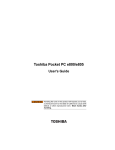
Front with the Display Closed
The Display latch keeps the display panel closed and locked. To
open the display panel, press the latch up and raise the panel.
The Modular bay comes with a CD or DVD drive installed. This
bay can accommodate a CD-ROM, CD-RW, DVD-ROM, or
multifunction DVD-ROM/CD-RW drive. It also supports a diskette
drive. The bay only supports one device at a time. It is designated
as drive D:.
The Battery bay has the main battery installed in it.
Display Latch
Modular Bay
Battery Bay
31
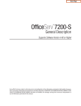
Left side
The Line In jack for an audio input device.
The Microphone jack let you connect external microphone or
other audio input device.
The Headphone jack lets you connect stereo headphones or other
audio-output devices such as external speakers. Connecting
headphones or other devices to this jack automatically disables
the internal speakers.
The SmartMediaTM slot is for digital SmartMediaTM cards which
are used in digital still cameras and various forms of portable
information equipment.
SmartMediaTM slot
Hard Disk Drive Bay
Line in Jack
Microphone Jack
Headphone Jack
32
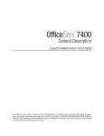
Right side
The two-stacked CardBus-ready PCMCIA-compatible PC card
slots allow you to install additional devices. Each slot can
accommodate one Type II PC card. Both slots are able to install
one Type III PC card.
CAUTION: Keep foreign objects out of the PC Card
slots. A staple or similar object that accidentally gets
into a slot can damage the computer’s circuitry.
The 1394 port is a 4-pin port for IEEE 1394 connecting i.Link®
(IEEE1394) standard devices.
This USB port allows you to connect USB peripherals to the
computer, such as a full-size USB keyboard or a USB pointing
device.
Type II PC Card Slot
Speaker
Type II/III PC Card Slot
USB Port
1394 Port
33
Rear Side
USB Ports
Modem Port
Security Lock Slot
TV-Out Port
Fan
DC-IN Socket
Parallel Port
Lan Port
VGA Port IR Port
The Fan prevents the computer’s central processing unit (CPU)
and internal electronic components from overheating.
CAUTION: To prevent possible overheating of the CPU,
never block the fan vents.
The DC-IN socket is where you plug in the AC adapter.
The two USB (Universal Serial Bus) ports allows you to connect
USB peripherals to your computer, such as a printer, pointing
device .
DEFINITION: USB is a peripheral expansion standard
that supports a data- transfer rate of up to 12 Mbps. USB
peripherals has a single standard for cables and connectors. The USB standard allows you to install and
remove USB devices while the computer is on. Switching devices without turning off the computer is called
“hot swapping.”
34
The Parallel port let you connect a parallel printer, or other
devices including ECP-compatible devices.
The Modem port lets you connect to a standard telephone line
through a Modem cable
The LAN port, is an RJ-45 jack for using a standard LAN cable
to connect to a Local Area Network.
The TV out port allows you to connect to a television or TV
monitor with an S-video cable.
NOTE: There are two status indicator on the LAN
port. The right indicator grows green color when the
LAN port links with cable well, and the left one
flashes amber when the LAN is active.
Activity
Amber light
Link
Green light
The VGA port is a standard 15-pin VGA port for connecting an
analog display such as a desktop computer monitor.
The IR port is a fast infrared communication port that allows the
system to communicate with other IR-equipped devices.
The Security lock slot allows you to attach a Kensington® cable
lock to secure the computer to a desk or other object to prevent
theft of the computer.
35
Bottom Side
The Expansion Memory slot Cover protects the system memory
modules.
The Battery Release latch locks the battery in the battery bay
and prevents it from falling out. To release the battery, slide the
latch in the direction the arrow indicates.
The Modular Bay Release latch locks a device in the modular
bay. To release the device, slide the latch in the direction the
arrow indicates.
Battery Release Latch
Expansion Memory Slot Cover
Modular Bay Release Latch
36
Front with the Display Open
The LCD Screen is the computer’s primary display. There are
several LCD options available for this computer. The one you
have will depend on which model you purchased. The options
include:
• 14.1” TFT with SXGA+ (1400 x 1050) resolution
• 14.1” TFT with XGA (1024 x 768) resolution
• 13.3” TFT with XGA (1024 x 768) resolution
DEFINITION: TFT (Thin Film Transistor) is a type of
LCD flat panel display screen in which each pixel controlled by from one to four transistors. Screens with
TFT technology (sometimes called active-matrix
LCDs) provide better resolution than other types of
flat-panel LCD displays.
LCD Screen
Power Button
Keyboard
Touch Pad
37
The Power Button turns the computer on and off, or let system
enter lower power mode (Standby, Hibernation) depends on power
management setting in OS.
The Lid Switch can be used to control the LCD back light or let
system enter a lower power suspend mode depending on the power
management setting in the OS.
The Keyboard provides all the functionality of a full-size keyboard.
The front panel provides a palm rest to assist you in maintaining
proper posture while using the computer.
The keyboard function keys, when used with the Fn key, activate
various system functions, such as the LCD brightness control.
The Touch Pad is a pressure sensitive pointing device which works
like a mouse to position the cursor on the screen.
The two Touch Pad Control Buttons are essentially the same
function as mouse buttons.
Touch Pad
Secondary Button
Primary Button
38
System Status Indicators & Controls
The System Status Indicators & Controls are divided into two
sections, those on the Hinge Bar and those on the Base Panel.
MP3
The Hinge Bar indicators and controls include the following items from
left to right:
The Power LED lights blue when the computer is on or while
playing CD or MP3 audio tracks with the system turned off. It
flashes blue while the system is in Standby or Suspend mode.
The LED turns off when the computer is turned off or in
hibernation mode.
The Battery LED indicates the main battery’s current charge
or discharge status.
1.It light blue and solid on when the battery is fully charged.
2.It lights blue and blinking (LED on 1 second every 1 second)
while the battery is being charged with AC adapter.
3.It lights blue and blinking (LED on 1 second every 4 second)
when the battery capacity is below 10%.
4.It lights blue and blinking (LED on 1 second every 2 second)
when the battery capacity reaches 3%.
The DC-IN LED lights blue when the computer is connected to
the AC adapter and it is plugged into an AC power source.
39
The HDD LED flashes blue when the system is accessing the
hard disk drive.
CAUTION: Never turn off the computer while any of
the drives are in use. It may cause the data loss and
possible damage the drive.
The Modular Bay LED flashes when the system is accessing a
drive installed in the Modular Bay. The icon indicates either an
optical disc (CD-ROM, DVD-ROM, CD-RW, multifunction DVDROM/CD-RW) or floppy disk.
The Volume Control buttons adjust the audio volume level. Pressing
the Minus sign button lowers the volume. Pressing the Plus sign
raises it.
The Caps Lock LED lights when you press the Caps Lock key.
When this light is on, pressing a letter key on the keyboard
produces an uppercase (capital) letter.
The PAD Lock LED lights when the arrow control overlay is on.
When this light is on, pressing an overlay key moves the cursor in
the direction of the reddish white arrow printed on the left front of
the key instead of the letter printed on the key.
The Num Lock LED lights when the numeric keypad overlay is
turned on. When this light is on, pressing this hot key can enable/
disable the emdedded numeric keypad. It depends on keypad
on/of state, if keypad enable the Numeric lock state is logically
enabled. If keypad disables the Numeric function also disable.
The Wireless Communication (802.11B) switch turns on and off
the wireless networking transceiver. The left LED lights to indicate
that wireless networking is turned on.
40
The Internet button Press the Internet button will open Microsoft
Internet Explorer when the computer is turned on. When the
computer is off, press the button will turn it and launch the Microsoft
Internet Explorer.
The Application Press the Application button will bring up the EZ
Button application. You can specify a special function for it. If
the computer is turned off, pressing the button will turn on the
computer and launch the program you specified.
MP3
The CD and MP3 switch sets which audio playback mode to use,
either audio CD or MP3. Set modes as follows:
• CD Mode Press the button to set the system in CD mode.
Computer Power Off state: You can use the CD controls to
play an audio CD without turning on the computer.
Computer Power On state: Pushing the switch starts the
Windows Media Player which will play an audio CD you have
loaded in an optical drive in the Device Bay.
• Digital Mode Press the button to set the system in MP3 mode.
Computer Power Off state: Pushing the switch will turn on the
computer, loads Windows® operating system and starts the
Windows Media Player which will play MP3 audio tracks you
have selected.
Computer Power On state: Pushing the switch starts the
Windows Media Player which will play MP3 audio tracks you
have selected.
The four CD Control buttons control and optical drive installed in
the Device Bay. The buttons function like an audio CD player
controls and have the following functions:
• Previous/Fast Rewind Returns to the preceding track on the
disc.
41
• Play/Pause Starts playing the disc, or pause the disc if it is
currently playing.
• Next/Fast Forward Skips to the following track on the disc. If
a track is playing, it ast forwards through the track while the
button is pressed.
• Stop Stops a disc that is currently playing.
42
Chapter 2
Getting Started
Setting Up Your Computer
Connecting a Printer
Connecting An Alternate Pointing Device
Using the Computer for the First Time
43
Getting Started
This chapter provides tips for working comfortably, describes how
to connect components, and explains what to do the first time you
use your notebook computer.
Making Sure You Have Everything
Before doing anything else, consult the Quick Start card to make
sure you received everything. If any items are missing or damaged,
notify your dealer immediately.
Selecting a Place to Work
Your computer is portable and designed to be used in a variety of
circumstances and locations.
44
Creating a Computer-Friendly Environment
Place the computer on a flat surface, which is large enough for
the computer and any other items you need to use, such as a
printer. Leave enough space around the computer and other
equipment to provide adequate ventilation and prevent
overheating.
To keep your computer in prime operating condition, protect
your work area from:
• Dust, moisture, and direct sunlight.
• Liquids and corrosive chemicals.
CAUTION: If you spill liquid into the computer, turn it
off, unplug it from the AC power source, and let it dry
out completely before turning it on again. If the computer does not operate correctly after you turn it back
on, contact a authorized service provider.
• Equipment that generates a strong electromagnetic field, such
as stereo speakers (other than speakers that are connected to
the computer) or speakerphones.
• Rapid changes in temperature or humidity and sources of
temperature change such as air conditioner vents or heaters.
• Extreme heat, cold, or humidity. Use the computer within a
temperature range of 5° to 35° C and 20% to 80% noncondensing humidity.
45
Keeping Yourself Comfortable
Strain and stress injuries are becoming more common as people
spend more time using their computers. However, with a little care
and proper use of the equipment, you can work comfortably
throughout the day.
This section provides hints on avoiding strain and stress injuries.
For more information, consult books on ergonomics, repetitivestrain injury, and repetitive-stress syndrome.
Computer Placement
Proper placement of the computer and external devices is important
to avoid stress-related injuries.
• Place the computer on a flat surface at a comfortable height
and distance. You should be able to type without twisting
your torso or neck, and look at the screen without slouching.
• If you are using an external monitor, the top of the display
should be no higher than eye level.
• If you use a paper holder, set it at about the same height and
distance as the screen.
Seating and Posture
When using your computer, maintain good posture with your body
relaxed and your weight distributed evenly. Proper seating is a
primary factor in reducing work strain. Some people find a backless
chair more comfortable than a conventional chair.
46
Correct posture and positioning of
the computer
Whichever type you choose, use the following guidelines to adjust
your chair for maximum computing comfort.
The proper position to the K/B is at or slight below to the leavel of
your below. so that your forearm will parellel to the grand. You
should be able to type with relaxed shoulder.
Keep your knees a little higher than your hips. If necessary, use
a footrest to raise your knees for eas the preasure on back of
your thighs.
Make your spine be well support by the chair back. If need, you
can adjust the chair back or use a lower back supported cushion
which are available at many office supply stores.
Lighting
Proper lighting can improve the visibility of the display and reduce
eyestrain.
• Position the display panel or external monitor so that sunlight or
bright indoor ligndows or shades to reduce glare.
• Avoid placing your computer in front of a bright light that could
shine directly in your eyes.
•If possible, use soft, indirect lighting in your computer work
area.
47
Arms and wrists
• Avoid bending, arching, or twisting your wrists. Keep them in a
relaxed, neutral position while typing.
• Exercise your hands, wrists, and arms to improve circulation.
WARNING: Using the computer keyboard incorrectly
may result in discomfort and possible wound. If your
hands, wrists, and/or arms bother you while typing, stop
using the computer and rest. If the discomfort persists.
Consult a physician.
Work Habits
The key to avoiding discomfort or injury from strain is to vary your
activities. If possible, schedule a variety of tasks into your working
day. Finding ways to break up the routine can reduce stress and
improve your efficiency.
• Take frequent breaks to change position, stretch your muscles,
and relieve your eyes. A break of two or three minutes every half
hour is more effective than a long break after several hours.
• Avoid performing repetitive activities for long periods. Intersparse
such activities with other tasks.
• Focusing your eyes on your computer screen for long periods
can cause eyestrain. Look away from the computer frequently
and focus your eyes on a distant object for at least 30 minutes.
48
Other Precautions
Your computer is designed to optimize safety, minimize strain,
and withstand the rigors of portability. However, you should
observe certain precautions to further reduce the risk of personal
injury or damage to the computer.
WARNING: Avoid prolonged physical contact with the
underside of the computer. If the computer is used for
long periods, its case can become very warm. While
the temperature may not feel too hot to the touch, if
you maintain physical contact with the computer for a
long time (if you rest the computer on your lap, for example), your skin might suffer low-heat injury.
CAUTION: Never apply heavy pressure to the computer or subject it to sharp impacts. Excessive pressure or impact can damage computer components or
otherwise cause you computer to malfunction. Some
PC Cards can become hot with prolonged use. If two
cards are installed, both can become hot even if only
one is being used. Overheating of a PC Card can result in errors or instability in its operation. Be careful
when you remove a PC Card that has been used for a
long period.
49
Setting Up Your Computer
Setting up your computer may include:
• Connecting the AC adapter
• Charging the battery
• Connecting a printer
• Connecting an alternate pointing device
Connecting the AC Adapter
Your computer contains a rechargeable battery pack,
which needs to be charged before you can use it the
first time.
The AC adapter enables you to power the computer from an AC
outlet and to charge the computer’s batteries. An LED on the AC
adapter lights green when Adapter is plugged into an outlet.
To connect AC power to the computer:
1. Connect the power cable to the AC adapter.
50
2. Plug the AC adapter into the computer’s DC-IN socket.
DC-IN Socket
3. Connect the power cable to an AC power outlet.
The LED on the AC adapter comes on. If the battery is being
charged, the Battery LED on the Hinge Bar of system indicator
will light blue and blink. Once the battery is fully charged the
battery light turns blue.
DANGER: To avoid electric shock, do not modify forcibly bend, damage, place heavy objects on top of, or
apply treat to the power cable. If the power cable becomes damaged or the plug overheats, discontinue
use. Never remove the power plug from the outlet with
wet hands.
CAUTION: Using the wrong AC adapter could damage your computer. We assumes no liability for any
damage in such cases. Never pull directly on the
power cable to unplug it. Hold the power plug when
removing the cable from the outlet.
51
Charging the Battery
Before you can use the battery to power the computer, you must
charge it. Connect the computer to an AC power outlet using the
AC adapter and power cable. The DC-IN LED will light and the
Battery LED will light blue and blinking.
Once the computer is connected to a power outlet, you can charge
the battery with the computer turned off or on. When the computer
is turned off, the battery charges in about 3.0 hours.
NOTE: When the computer is turned on and is not consuming full power (under 18W), the battery charges in
about 3.5 to 8 hours.
CAUTION: Once the battery is charged for the first time,
avoid leaving the computer plugged in and turned off
for more than a few hours at a time. Continuing to charge
a fully charged battery may impact the battery.
52
Connecting a Printer
Before connecting a printer, you need to know whether it requires
a USB or a parallel interface. Check the printer’s documentation.
If the printer can be switched between USB and parallel mode
choose parallel if you want to leave your USB ports free for
other use.
You also need a suitable printer cable which may come with
your printer. If not, you can purchase one from a computer or
electronics store.
CAUTION: Connecting the printer cable while the
computer is on may damage the printer, the computer, or both.
NOTE: If your printer is ECP-or IEEE- compliant,
make sure your printer cable is an IKE 1284 cable.
The following instructions assume you have a printer that uses a
parallel port connection, which is the most common type of printer
interface.
1. Turn off the computer.
2. Connect the printer cable to the printer and to the computer’s
parallel port.
3. Plug the printer’s power cable into an AC outlet.
4. Refer to your printer documentation for additional configuration
steps.
53
Connecting An Alternate Pointing
Device
You may want to use an external mouse or trackball instead of the
computer’s built-in Touch Pad pointing device. Your computer
supports USB-compatible pointing devices.
The Touch Pad remains operable, even if you connect a millenary
pointing device to the computer.
Using a USB Pointing Device
1. Plug the USB pointing device cable into one of the USB ports.
We recommend the USB port on the right-side of the computer.
For left-handded user’s, use one of the rear USB ports.
2. Refer to your device documentation for configuration steps.
USB Ports
USB Port
NOTE: In Windows® Millennium Edition, the green question mark is displayed on USB Universal Host Controller-2485/2484/2487, the reason is the newer USB controller was unknown at the time Windows® Millennium
Edition was release, the USB function no any loss.
54
Using the Computer for the First
Time
Flip the display panel latch up to release it and then lift the display
panel to open the computer.
CAUTION: Don’t force the display panel open beyond the point where it moves easily. Never lift or
move the computer by grasping the display panel.
55
Turning On the Computer
1. Make sure that the diskette drive is empty.
2. Open the display panel.
3. If you have a printer connected to your computer, turn the
printer on and wait until it indicates it is ready.
4. Turn on the computer by momentarily pressing then releasing
the power button.
When you release the power button, the Power LED on the system
indicator Hinge Bar comes on.
NOTE: When turning on the computer for the first time.
Don’t turn it off until the operating system has loaded
completely. Turning off the computer during its initial
startup will cause an error the next time you start the
computer.
NOTE: When the computer is connected to an external power source, the DC-IN LED lights. If the battery is
being charged, the Battery LED lights pink.
NOTE: The HDD LED flashes when the hard disk
drive is accessed.
CAUTION: To avoid data loss, never turn off the computer while a drive is in use.
56
Hot keys
Fn + F5 Power on display. When pressing the hot key, the
display device will switch among CRT only, LCD only
and simultaneous display. It will not update the setting
of option ‘Power on Display’ in system setup.
Fn + F10 Cursor keypad on/off. Pressing this hot key can
enable/disable the embedded cursor keypad.
Numeric lock state is logically disabled.
Fn + F11 Numeric keypad on/off. Pressing this hot key can
enable/disable the embedded numeric keypad. It
depends on keypad on/off state, if keypad enable the
Numeric lock state is logically enabled. If keypad
disables the Numeric function also disable.
Fn + F12 Scroll Lock on/off.
Fn +
Increase brightness
Fn +
Decrease brightness
After rebooting, pad lock is set to off and Num lock is set to off
also. In this state, the embedded cursor numeric keypad is not
enabled on the notebook keyboard.
57
Using the Touch Pad
The Touch Pad is a touch-sensitive point device that provides all
the features of a mouse. Please refer to the following instructions
on how to operate the Touch Pad.
The Touch Pad is easily accessible by moving either your finger
off the space bar and onto the Touch Pad.
Gently move your finger across the Touch Pad in the direction
you want the cursor to move. The pad detects the change in
pressure and moves the cursor in the corresponding direction.
With a conventional mouse, selections are usually made by double
clicking the mouse’s left button. The Touch Pad also supports this
feature. It is described in detail below. If you are familiar with the
operations of a mouse you may only need to skim the information
below.
The Touch Pad buttons have essentially the same function as mouse
buttons. Clicking these buttons makes selections, drags object, or
performs a variety of other functions depending on the software.
To select an object, first move the pointer to the object you want to
select, and then press the left button one time and release it. The
functionality of these buttons depends on your software. Refer to
your software user’s manuals for specific information on the Touch
Pad (mouse) functions.
58
Double clicking is a common technique for selecting objects or
launching programs from icons. Move the pointer over the object
you wish to select, then rapidly press the left button two times.
This action is commonly referred to as “double clicking on an
object.
Double tapping is another technique for selecting objects or
executing applications from icons. For the most part double tapping
is very similar to the double clicking technique of a mouse. The
difference is that instead of double clicking on a mouse button,
you double tap on the pressure sensitive touch pad to make the
selection. Once the cursor has been moved the object you want
select, lightly double tap the Touch Pad itself. The double tapping
will select the desired item and prompt the software to perform
the related operation.
Many of the functions within Microsoft® Windows® series operating
system can also be launched by using single tap on the Touch
Pad. This single tapping will select the desired item and prompt
the software to perform the related operation.
When working with programs that employ a graphical user
interface (GUI), such as Windows®, dragging objects from one
point on the screen to another is a technique you will have to
master. To drag an object, first move the pointer over the object,
then press and hold down the left button. Now without releasing
the button, move the object to a new location on the screen by
moving your finger across the Touch Pad. Once the object is in
the desired position, release the button to drop the object in place.
59
Chapter 3
Precautions
Computing Tips
Using the keyboard
Starting a Program
Saving Your Work
Printing Your Work
Backing Up Your Files
Using Compact Discs
Using PC Cards
Using Your Computer at the Office
Setting Up Communications
Turning Off the Computer
Caring for Your Computer
60
Learning the Basics
This chapter covers precautions and computing tips that you
should follow when using your computer. It also provides important
information about the basic features of your system.
Precautions
• Don’t spill liquids into the computer’s keyboard.
If you did spill a liquid that gets into the keyboard, turn off the
computer immediately. Leave the computer turned off over night
to let it dry out before you use it again.
• Don’t turn off the computer if a drive light indicates a drive is
active.
Turning off the computer while it is reading from or writing to a
disc may damage the disk, the drive, or both.
• Keep the computer and disks away from objects that generate
strong magnetic fields, such as large stereo speakers.
Information on disks is stored magnetically. Placing a magnet
too close to a disk can erase important files.
• Scan all new files for viruses.
This precaution is especially important for files you receive via
diskette, email, or download from the Internet. Occasionally, even
new programs you buy from a supplier may contain a computer
virus. You’ll need a special program to check for viruses. Ask
your dealer to help you.
61
To turn the numeric overlay on and off, press Fn and F11
simultaneously. The numeric mode light on the status panel glows
when the numeric overlay is on.
You can still use the overlay keys to type alphabetic characters
while the numeric overlay is on.
• For lowercase letters, hold down Fn while you type the letters.
• For uppercase letters, hold down both Fn and shift while you
type the letters.
To use the cursor control keys when the numeric overlay is on,
press and hold down Shift while you use the cursor control keys
To return to the numeric overlay, release Shift.
Using the Cursor Control Overlay
To turn the cursor control overlay on and off, press Fn and F10
simultaneously. The cursor control light on the keyboard indicator
panel glows when the cursor control overlay is on.
To type alphabetic characters while the overlay is on:
• For lowercase letters, hold down Fn while you type the letters.
• For uppercase letters, hold down both Fn and Shift while you
type the letters.
To use the numeric overlay keys when the cursor control overlay is
on, hold down Shift while you use the numeric overlay keys. To
return to the cursor control overlay, release Shift.
62
Using the keyboard
85-key keyboard
Character Keys
Typing with the character keys is very much like typing on a
typewriter, except that:
• The spacebar creates a space character instead of just passing
over an area of the page.
• The lowercase letter I and the number 1 are not interchange
able.
• The uppercase letter O and the number 0 are not interchange
able.
The Caps Lock key shifts the letter keys to upper case – the
number and symbol keys are not affected. The Caps Lock LED
on the keyboard indicator panel illuminates when you press the
Caps Lock key.
63
Ctrl, Fn, and Alt keys
The Ctrl, Fn, and Alt keys do different things depending on the
program you are using. For more information, see your program
documentation.
Function keys
The function keys (not to be confused with the Fn key) are the 12
keys at the top of the keyboard.
Through F1 to F12 are called function keys because they perform
programmed functions when pressed. Used in combination with
the Fn key, function keys marked with icons execute specific
functions on the computer.
Windows Special Keys
The keyboard provides two keys that have special functions in
Windows. The Windows key activates the Start menu. The
Application key has the same function as the secondary mouse
(or the Touch Pad) button.
Windows Logo Key
Application Key
64
Overlay Keys
The keys with numbers and symbols on the front of them form
the numeric and cursor overlay. This overlay lets you enter
numeric data or control the cursor as you would use the ten-key
keypad on a desktop computer’s keyboard.
To turn the numeric overlay on and off, press Fn and F10 first
then press Fn and F11 simultaneously. The numeric mode light
on the status panel glows when the numeric overlay is on.
You can still use the overlay keys to type alphabetic characters
while the numeric overlay is on.
• For lowercase letters, hold down Fn while you type the letters.
• For uppercase letters, hold down both Fn and shift while you
type the letters.
To use the cursor control keys when the numeric overlay is on,
press and hold down Shift while you use the cursor control keys
To return to the numeric overlay, release Shift.
65
Using the Cursor Control Overlay
To turn the cursor control overlay on and off, press Fn and F10
simultaneously. The cursor control light on the keyboard indicator
panel glows when the cursor control overlay is on.
To type alphabetic characters while the overlay is on:
• For lowercase letters, hold down Fn while you type the letters.
• For uppercase letters, hold down both Fn and Shift while you
type the letters.
To use the numeric overlay keys when the cursor control overlay
is on, hold down Shift while you use the numeric overlay keys. To
return to the cursor control overlay, release Shift.
Starting a Program
There are three ways to start a program in Microsoft® Windows®
series operating system which are from the Start menu, from the
Windows Explorer, or from the Run menu on the taskbar.
Starting a program from the Start menu
1. Click Start, then point to Programs.
Microsoft® Windows® series operating system displays the
Programs menu, which lists programs and program groups. If
your program is listed, go to step 3; otherwise, continue with step
2.
2. Point to the program group containing the program that you
want to start.
Microsoft® Windows® series operating system displays the
associated program menu.
3. Click the program’s icon to start the program.
To close the program, click the Close button at the upper-right
corner of the program’s window.
66
Starting a Program from Windows Explorer
If a program is not in the Programs menu, you can start it from
Windows Explorer. Windows Explorer gives you a view of your
computer’s contents as a hierarchy or “tree.” You can easily
see the contents of each drive and folder on your computer. To
use this method, you need to know the name and location of the
program’s executable file (this file ends with “.exe”.)
1. Click Start, point to Programs, and then clicks Windows
Explorer.
• The left side of the window displays the disk drives and folders
on your computer.
• The right side of the window displays the contents of the item
you click on the left.
2. To open a document or start a program, double-click its icon
in the right side of the window.
Starting a Program from the Run Menu
You can start a program from the taskbar if you know its name
and location.
1. Click Start on the taskbar.
2. Point to Run.
3. In the dialog box, type the command line.
4. Click OK.
Saving Your Work
Before you turn off the computer, save your work to the hard
disk drive or a diskette. This is one of the most important rules of
computing.
67
NOTE: Save your data even when you are using
Standby, in case the battery discharges before you
return to work.
Many programs offer a feature that saves documents at regular
intervals, such as every 15 minutes. Check your program’s
documentation to see whether they have an automatic save feature.
• To save a file you are updating, open the program’s File menu
and click Save.
• To save the current file with a new name, choose Save As from
the File menu, type a name for the file and click OK.
HINT: To make another copy of the file you are currently working with, choose Save As from the File
menu and give the new file a different name.
File Names
Microsoft® Windows® series operating system supports file names
of up to 255 characters. You may use all the letters and numbers
on the keyboard plus the following characters: _, ^, $, ~, !, #, %,
&, {, }, (, ), @, [, ], +, -, ;, and ’. The names can include spaces.
If you plan to share your files with a computer using MS-DOS® or
a pre-Windows® 95 version of Windows, the file name must be no
more than eight characters followed by a period and a three
character extension. An MS-DOS file name may not contain a
space.
Most programs assign an extension that identifies the file as having
a particular format. For example, Microsoft® Word saves files with
a .doc extension.
68
Printing Your Work
Make sure that the Microsoft® Windows® series operating system
is set up for your printer.
TECHNICAL NOTE: You only need to setup the printer
the first time you connect it. If you use more than one
printer or are changing printers, you will need to setup
your Microsoft® Windows® operating system to run with
the additional printer(s).
1. If your printer is not on, turn it on now.
2. In the File menu of your Windows program, click Print.
The program displays a Print dialog box similar to the one below.
A sample Print dialog box
3. Click OK to print.
69
Backing Up Your Files
Backing up your files simply means copying individual files to a
floppy disk or copying entire sections of your hard disk to another
media, such as a CD-R or CD-RW discs.
Copying to a diskette
1. Insert a formatted floppy disk into the floppy disk drive.
2. Double-click the My Computer icon on the Windows desktop.
3. Double-click the drive that contains the file you want to copy.
4. Double-click the folder containing the file, then click the file you
want to copy.
HINT: Use the Ctrl or Shift keys to select more than
one file.
5. Click File, then click Send To.
6. Click the icon for the diskette drive.
HINT: You can also back up a file to a diskette by
clicking the file (or files) you want to backup with the
secondary button, then pointing to Send To and clicking 3 1/2 Floppy (A:).
70
Using Compact Discs
The CD-ROM drive lets you read CD-ROM discs and play audio
Compact Discs.
CAUTION: When inserting and removing CD-ROM
discs, be careful not to touch the lens on the disc tray
or the area around it, due to it may cause the drive to
malfunction.
The CD-ROM Drive
Eject Button
Manual Eject
Press the eject button to open the disc tray. The eject button will
not open the disc tray when the computer is off.
The manual eject button—accessed through the small hole just
to the right of the eject button allows you to open the disc tray
when the computer is off.
Inserting compact discs into the CD-ROM drive
1. With the computer turned on, press the eject button to open
the disc tray.
2. Pull the disc tray until it is fully open.
3. Hold the CD by its edges, ensure it is dust-free, and place it
carefully in the disc tray, with the label side up.
4. Press down on the CD until the disc locks on the spindle.
71
5. Close the disc tray.
CAUTION: If the CD is not seated properly when you
close the disc tray, the CD might be damaged and the
tray may not open fully when you press the eject button.
Removing a CD with the Computer on
1. Press the eject button.
CAUTION: Do not press the eject button while the
computer is accessing the CD-ROM drive. If the CD is
still spinning when you open the disc tray wait for it to
stop before you remove it.
2. Pull the disc tray until it is fully open, remove the CD, and place
it in its protective cover.
3. Close the disc tray.
Removing a CD with the Computer Off
1. Insert a slender object, such as a straightened paper clip, into
the manual eject hole.
CAUTION: Never use a pencil to press the manual
eject button. Pencil lead can break off inside the computer end and damage the devices.
2. Pull the disc tray until it is fully open, remove the CD, and place
it in its protective cover.
3. Close the disc tray.
72
Caring for Compact Discs
• Store your CDs in their original containers to protect them from
scratches and keep them clean.
• Don’t bend a CD or place heavy objects on top of it.
• Don’t apply a label to, or otherwise mar, the surface of a CD.
• Hold a CD by its outside edge. Fingerprints on the surface of a
CD can prevent the drive from reading the data properly.
• Don’t expose CDs to direct sunlight or extreme heat or cold.
• To clean a CD, wipe it with a clean, dry cloth—starting from the
center of the CD and wiping toward the outward edge. Do not
wipe using a circular motion. If necessary, moisten the cloth with
water or a neutral cleaner (not benzene or rubbing alcohol). Let
the CD dry completely before inserting it in the drive.
Using PC Cards
PC Cards expand your computer’s capabilities and usefulness.
You can purchase additional PC Cards from your dealer. Most
PC Cards conform to the PCMCIA (Personal Computer Memory
Card International Association) standard.
Your computer comes with two stacked PC Card slots and supports
two types of PC Card:
• Type II cards are typically used for fax/modems, memory
storage, network cards, etc. You can install up to two of these
cards, one in each slot.
• Type III cards are used for removable hard disks and other
functions that require a larger card. You can install just one of
these cards.
73
Check the documentation that came with the PC Card to see if it
conforms to the PCMCIA 2.1 standard, or later. Other cards may
work with your computer, but are likely to be much more difficult to
set up and use.
Inserting PC Cards
PC Cards require Card and Socket Services software a set of
programs that acts as a translator between the PC Card and the
computer, and that makes hot swapping (switching cards while the
computer is on) possible.
TECHNICAL NOTE: Microsoft® Windows® series operating system provides the Card and Socket Services
for your PC Card. Even if your PC Card comes with its
own version of Card and Socket Services, you should
use the files included in Microsoft® Windows ® series
operating system. Some PC Cards do not support Hot
swapping. Refer to your PC Card’s manual for information.
1. If your PC Card does not support hot swapping, save your
data and turn off the computer before inserting the PC Card. For
more information, see “Hot swapping”.
2. Hold the PC Card with the arrow side up and the connector
side toward the slot.
3. Align the card connectors with an available PC Card slot and
carefully slide the card into the slot until it locks into place.
There are two eject buttons, one per slot. When the PC card is
seated, the eject button for that slot pops out.
4. Press the eject button to put it in its retracted position.
74
NOTE: If you have a Type III card, insert the connector into the lower slot. If you have a Type II card, insert it into either the upper or the lower slot.
Type II PC Card Slot
Type II/III PC Card Slot
NOTE: An HDD or CD-ROM connected to a 16-bit PC
card, might affect the performance of the computer’s
sound system and data transmission, including
slower transmission speeds and dialing errors.
CAUTION: To avoid damaging the computer or the
PC Card, don’t force the card into the slot.
Removing PC Cards
1. Click the PC Card button on the taskbar.
2. Click Stop xxxx where xxxx is the name of the PC Card you
want to stop.A message will appear indicating that you may
safely remove the card.
3. To remove the PC Card, press the respective eject button
once. The eject button pops out.
75
CAUTION: If your PC Card supports hot swapping, you
can remove it at any time. However, to avoid data loss,
never remove a card while it is in use. For more information, see “Hot swapping”.
4. Press the eject button again to eject the PC Card. The upper
eject button will eject Type II PC Card from the upper slot. The
lower button will eject a Type II, or Type III card from the
lower slot.
5. Remove the PC Card and store it properly.
PC Card Slots
PC Card Eject Button
Hot swapping
With PC Cards, you can replace one PC Card with another while
the computer is on. This is called “hot swapping.”
Hot swapping precautions
Although you can insert a PC Card at any time, to avoid data loss
do not remove a card while it is in use. Before removing a PC
Card, stop it by clicking the PC Card (PCMCIA) icon on the taskbar.
After the PC Card is stopped, it is safe to remove it.
• Don’t remove a hard disk card while the system is accessing it.
• Don’t remove a network card while you are connected to a
network.
76
• Don’t remove a SCSI card while any of the SCSI devices
connected to it is operating.
DEFINITION: SCSI is an acronym for Small Computer
Systems Interface. A single SCSI PC Card enables
you to connect several SCSI devices, such as a scanner or digital camera to your computer.
Using Your Computer at the Office
By connecting an external monitor, external full-size keyboard,
and a mouse, you can work with your notebook as if it were a
standard office computer.
An external monitor connects to the monitor port.
Any USB devices including an external keyboard and pointing
device connect to the USB ports.
Using a Computer Lock
You may want to secure your computer to a heavy object such
as your desk. The easiest way to do this is to purchase a
computer cable lock.
1. Loop the cable through or around some part of a heavy object.
Make sure there is no way for a potential thief to slip the cable
off the object.
77
2. Pass the locking end through the loop.
3. Insert the cable’s locking end into the security lock slot, then
rotate the key a quarter turn and remove it.
Security Lock Slot
Setting Up Communications
To connect to the Internet, use an online service, or communicate
across the telephone lines with another computer, you need:
• A modem (supplied with your notebook computer)
• A telephone line
• A browser or communications program
• An Internet Service Provider (ISP) or online service if you plan
to use the Internet
CAUTION: Never connect the Modular jack to a digital
line. Digital line’s high current can damage the modem.
78
Connecting the Modem to a Telephone Line
Before you can use the modem, you must connect it to a standard
voice-grade telephone line.
TECHNICAL NOTE: Disable Call Waiting before you
connect through the modem. Call Waiting interrupts
data transmission.
NOTE: If you use a storage device such as a CDROM drive or HDD connected to a 16-bit PC card,
modem speed might be slow or communication
might be interrupted.
1. Plug one end of a standard RJ-11 telephone cable into the
modem port.
2. Plug the other end of the RJ-11 telephone cable into the modular
jack of a standard voice-grade telephone line.
NOTE: The plug may be different in your country.
Modem Port
79
Connecting Directly to a Remote Computer
If you are connecting directly to a remote computer or a bulletin
board service (BBS), you need a general-purpose communications
program.
In addition, there are two things you need to know before you can
connect to another computer:
• The communications parameters
• The file transfer protocol (only if you are downloading or uploading
files)
Communications Parameters
There are four communications parameters:
• Modem speed - The speed at which the modem transfers
information. Speeds are measured in bits per second.
• Data bits - The number of bits in one character. This number is
usually seven or eight.
• Stop bit - Indicates the end of a character. This number is
usually one or two.
• Parity - An error-checking method, which will be set to even,
odd, or none.
Communications parameters, except for the modem speed, are
usually abbreviated and combined. Common examples are N81
(no parity, eight data bits and one stop bit) and E72 (even parity,
seven data bits and two stop bits).
You set each of these parameters in your communications
program. Each parameter must be set the same on both computers
or you will not be able to connect.
80
File Transfer Protocols
File transfer protocols are standards that given how computers
transfer files between modems over a telephone line. You do not
really need to know anything about specific protocols-just make
sure you are using the same protocols as the computer with
which you are communicating.
Turning Off the Computer
It is a good idea to turn off your computer when you are not
using it for a while.
• If you have work in progress and expect to resume shortly, use
your Microsoft® Windows® operating system Standby command
to save your system settings so that, when you turn on the
computer again, you automatically return to where you left off.
To leave the computer turned off for a longer period, use your
Microsoft® Windows® operating system Shut Down command
instead.
• Never turn off the power if the hard disk drive light is on. It may
damage your hard disk drive.
81
Caring for Your Computer
This section gives tips on cleaning and moving your computer.
For information about taking care of your computer’s battery, see
“Running the computer on battery power” in Chapter 5.
Cleaning the Computer
To keep your computer clean, gently wipe the display panel and
exterior case with a lightly dampened cloth. Ask your dealer for
suggestions for appropriate cleaning products.
CAUTION: Keep liquid, including cleaning fluid, out of
the computer’s keyboard, speaker grille, and other
openings. Never spray cleaner directly onto the computer. Never use harsh or caustic chemical products
to clean the computer.
Moving the Computer
Before moving your computer, even across the room, make sure
that all disk activity has ended and all external peripheral cables
are disconnected.
CAUTION: Don’t pick up the computer by its display/
panel or by the back (where the ports are located).
82
Chapter 4
Energy-Saving Design
Managing Power Usage
Charging Batteries
Monitoring Battery Power
Conserving Battery Power
Battery Alarms
Changing the Main Battery
Disposing of Used Batteries Safely
Traveling Tips
83
Mobile Computing
This chapter covers all aspects of using your computer while
traveling.
Energy-Saving Design
Your computer enters a low-power state when it is not being used,
thereby conserving energy and saving money in the process. It
has a number of other features that enhance its energy efficiency.
Many of these energy-saving features. We recommend you leave
these features active, allowing your computer to operate at its
maximum energy efficiency, so that you can use it for longer periods
while traveling.
84
Managing Power Usage
Your computer’s power-saving options greatly increase the length
of time you can use the computer before you need to recharge
the battery.
To change the power usage mode, click Start, point to Settings,
then click Control Panel. In Control Panel, double-click the Power
Option icon to display the Power Option Properties window.
Select the power scheme with the most appropriate settings for
your computer. Keep in mind that changing any settings on the
Power Option Properties window will modify the currently selected
scheme.
Consult your Microsoft ® Windows ® operating system
documentation for more information on the Power Option utility.
Running the Computer on Battery Power
The computer uses a removable Lithium Ion (Li-ION) battery
pack that provides power when you are away from an AC power
source. You can recharge it many times.
In addition to the removable main battery, the computer has an
internal real-time clock (RTC) Lithium rechargeable battery. The
RTC battery powers the RTC memory, which stores your system
configuration settings and the current time and date for up to a
month while the computer is turned off.
85
Using Additional Battery Packs
If you spend a lot of time traveling and need to work for many
hours without an AC power source, you may want to carry
additional charged battery packs with you. You can then replace a
discharged battery and continue working.
NOTE: A new battery pack should be fully discharged
and recharged three times before being used.
Maximizing Battery Life
A main battery can be recharged many times. Gradually over time
it will lose its ability to hold a charge. To maximize the life of your
main battery:
• Don’t leave the computer plugged in and unused for more than
a few hours. Overcharging the main battery may shorten its life.
• If you are not going to use the computer for a long period of
time, remove the battery.
• Alternate between battery packs if you have a spare.
• Make sure the computer is off when you are replacing the battery.
• Store spare battery packs in a cool dry place out of direct sunlight.
86
Charging Batteries
The main battery needs to be charged before you can use it to
power the computer. You can charge the battery using your
computer.
Charging the Main Battery
To charge the batteries while they are in your computer, plug the
computer into a live AC outlet. It takes approximate 3.0 hours to
charge the battery to full while the computer is off. It takes much
longer to charge a battery to full while the computer is on.
TECHNICAL NOTE: The battery only can charge a
small current while the computer Is consuming full
power.
The battery may not start charging immediately if:
• The battery is extremely hot or cold.
To ensure that the battery charges to its full capacity, wait until
it reaches room temperature: 5°C to 35°C. (41°F to 95°F).
• The battery is almost completely discharged.
Leave the power connected, and the battery should begin
charging after a few minutes.
HINT: Once a battery pack is fully charged, we recommend that you operate your computer on battery
power until the battery pack discharges completely.
Doing this extends battery life and helps ensure
accurate monitoring of battery capacity.
87
Charging the RTC Battery
In addition to the main battery, the computer contains an internal
battery for the real-time clock (RTC). The RTC battery provides
power for the internal real-time clock and calendar.
During normal use, the main battery keeps the RTC battery
adequately charged. Occasionally, the RTC battery may lose its
charge completely, especially if you have had the computer turned
off and without main battery pack inserted for a long time.
It is seldom necessary to charge the RTC battery because it
charges while the computer is on. However, if the RTC battery is
low, the real-time clock and calendar may display the incorrect
time and date or stop working.
To recharge the RTC battery, plug the AC adapter into the computer
for at least 24 hours.
The computer can be used while the RTC battery is being charged.
Although the charging status of the RTC battery cannot be
monitored, if the power is on, it takes approximately 24 hours to
fully charge the RTC battery.
Monitoring Battery Power
The battery LED on the system indicator panel comes on when
you are using the battery to power the computer.
HINT: Be careful not to confuse the battery light with
the on/off light. When the on/off light flashes, it indicates that the system is in Standby mode.
88
Determining Remaining Battery Power
NOTE: Wait at least 20 seconds after turning on the
computer before checking the remaining battery
power. The computer needs this time to check the
battery’s remaining capacity and perform calculations.
To check the battery level, you can look at the Microsoft®
Windows® operating system Power Meter control panel. To
access the panel:
1. Click on the Start button, point to Settings, and then click
the Control Panel.
2. Double-click the Power Options icon.
3. Choose the Power Meter tab to show the current battery
status. The meter displays a percentage of a full battery charge
remains.
TECHNICAL NOTE: The computer drains the battery
faster at low temperatures. Check your remaining
charge frequently if you are working in temperatures
below 10 degrees Centigrade. The computer calculates the remaining battery charge based on your current rate of power use and other factors such as the
age of the battery.
NOTE: When removing or inserting the battery pack,
click on the Power Meter tab to show the latest battery status.
89
Conserving Battery Power
How long a fully charged battery pack lasts when you are using
the computer depends on a number of factors, such as:
• How is the computer configured?
• How much do you use the display panel instead of an external
monitor?
• How much do you use the hard disk and other drives?
• Do you use any optional devices that the battery supplies power
to, such as a PC Card?
• What is your working condition (operating time decreases at
low temperatures)?
What To Do When the Battery Runs Low
When the battery runs low you have these options:
• Plug the computer into a live AC outlet and recharge the battery.
• Save your work and turn off the computer.
If you don’t manage to do any of these things before the battery
completely runs out of power, the computer automatically enters
Standby and keeps track of where you were so. When you turn
on the power by using AC adapter again, you can continue where
you left off.
90
Battery Alarms
The computer can be configured to warn you when the battery is
running low. You can set each of the following alarms:
• Low Battery
• Critical Battery
Each alarm can be set to alert you when a specified percentage
of remaining battery power has been reached. You can also set
how the alarm action occurs – sound an alarm, display a
message, both, or none. You can also set the computer to enter
Standby when the alarm goes off.
To set the alarm levels:
1. Click the Start button, point to Settings, and then click Control
Panel.
2. Double-click the Power Option icon.
3. Click OK to clear the Power Option Advisory dialog box.
The Power Option dialog box appears.
4. Click the Alarm tab.
5. Set the alarm levels as desired.
For more information on battery alarms, refer to the Microsoft®
Windows® operating system documentation or Help.
91
Changing the Main Battery
When your battery runs out of power, you have two options connect
the AC adapter or install a fresh battery. For instructions on using
the AC adapter, see “Connecting the AC adapter”.
Removing the Battery
1. Save your work.
2. Shut down the computer. Never removes the battery while the
computer is on.
3. Close the display panel, ensuring that it snaps in to place.
4. Turn the computer upside down with the front of the computer
facing away from you.
5. Slide the Battery Release latch in the direction of the arrow.
6. Carefully pull the battery out of the Battery Bay.
NOTE: The Battery Release latch is spring-loaded
and will snap back into place when you release it.
92
Inserting a Battery
1. Wipe the battery terminals of the battery with a clean
cloth to ensure a good connection.
2. Slide the battery in to the Battery Bay. When the battery is
fully inserted, you should hear it click into place.
NOTE: The release latch is spring-loaded and clicks
as it latches the battery in place when you insert it.
3. Turn the computer bottom side up and ensure the battery is
fully inserted in the bay.
WARNING: If the battery housing is leaking or
cracked, put on protective gloves to handle it and
discard it immediately following the advice in the
section on “Disposing of Used Batteries Safely”.
93
Disposing of Used Batteries Safely
You can recharge a main battery many times. When the useful life
of the battery expires or if the battery becomes damaged, you
must discard it responsibly.
Batteries should not be disposed of together with household waste.
To make sure that they are forwarded to recycling or proper disposal
they may be returned free of charge to an authorized dealer/
distributor.
Only use replacement batteries recommended
CAUTION: The computer uses a Li-Ion battery which
can explode if not handled or disposed of properly. Putting spent batteries in the trash is not only irresponsible,
it may also be illegal. Dispose of the battery as required
by local ordinances or regulations.
94
Traveling Tips
The Environmental precautions also apply on journeys.
• Do not leave your computer exposed to direct sunlight for long
periods of time for instance, on the dashboard of a car or
place it here it could get wet or covered in dust.
• Always travel with the computer in a carrying case.
offers a choice of carrying cases for the computer. They all
provide plenty of extra space for manuals, power cables, CDROM discs, and floppy disks, etc. See your dealer for more
information.
WARNING: When traveling by air, you maybe required to put your notebook through airport security
The X-ray equipment used may or may not harm
your computer.
WARNING: Ensure your personal computer is turned
off before you put it in your bag.
95
Chapter 5
Advanced Features
Using the Modular Bay
Using the CD/Digital Switch to Play
MP3 Tracks Audio CD Player Feature
Using i.Link® Port (IEEE1394)
Using the SmartMediaTM Cards
Using the IR Port
Using Wireless LAN
Using the SpeedStep Utility
96
Using Advanced Features
This chapter explains many advanced features of your notebook
computer.
Advanced Features
Your notebook built in nVidia GeForce4 420 Go video display
hardware which supports superior 2D and 3D performance.
GeForce4 420 Go Features
You can either go into the GeForce4 420 Go settings through
Start, Settings, Control Panel, Display or, Right-click on the
Windows desktop then check Properties. Follow the on screen
display step by step panels, you will find the following settings.
1. nView: The nView allows you connect two separate output
devices which includes analog monitor, digital flat panel or TV.
You can connect to a TV through TV-OUT connector. The default
setup is nView disabled. You can do the Color Correction controls
at the panel too.
2. GeForce4 420 Go Settings: You can check the installed
technical information, customize Direct 3D Settings, customize
OpenGL setting, and show the nVidia QuickTweak utility on the
taskbar. By default, the setting is good enough for the most of
usages.
3. Overlay Controls: It allows you to adjust the display screen
appearance.
97
Using the Modular Bay
The modular bay supports one of following removable modules:
• CD-ROM drive
• CD-RW drive
• DVD-ROM drive
• DVD/CD-RW drive
• Floppy Disk drive
Your computer comes with some of these drives depending on
which model you purchased. You may purchase additional drives
separately as accessories.
Device Swapping
You can swap devices in the device bay when the computer is
turned off . The Microsoft® Windows® 2000 and XP operating
system support native driver utility of hot-swapping, you can swap
devices in the device bay either the computer turned off or turned
on. You can find the utility program on the right system task bar
tray.
CAUTION: You should always keep a device or battery installed in the modular bay. Don’t leave it empty.
98
Playing DVD
Your computer comes with the WinDVD software utility disc which
is for playing DVD movie titles. You have to install it by yourself.
Firstly, insert the disc into the drive, then the setup manual will
show up automatically. You can follow the on screen display step
by step method to install it. Please read the InterVideo WinDVD
on line Help for detail using instructions.
Using a CD-RW Drive
If your computer comes with either the CD-RW or DVD-ROM/
CD-RW drive, you can write to either CD-R or CD-RW media.
There is a disc called Easy CD Creator software that comes with
the drive. You have to installed the software by yourself. Firstly,
insert the disc into the drive, then the setup manual will show up
automatically. You can follow the on screen display step by step
method to install it. Please read the program Quick Reference
Guide for detail using instructions.
CAUTION : When using CD-RW device, do not copy
data directly from external device. (e.g USB, IEEE1394
device). Please copy the data into the Hard Disk Drive,
then copy to the CD-RW disk.
99
Using the CD/Digital Switch to Play
MP3 Tracks Audio CD Player Feature
This player application supports audio CDs direct play and MP3
with the computer turned off. To play MP3 files, you need to use
the Windows Media Player that comes with the Windows® operating
system. You can refer to previous Chapter 1 System Status
Indicators & Controls for instruction.
Using the Easy Buttons
The Easy Button utility program is preinstalled in your computer.
This software supports you to configure various button functions.
Most of the button functions are fixed which include Volume Control,
CD/Digital Switch, and CD Control Buttons. There are another two
programmable buttons on the Base Panel. They are the Application
button and the Internet button.
You can double-click the Easy Button icon on the system taskbar
to configure the Application button or Internet button. By default:
Pressing the Application button will bring up the Easy Button
application.
Pressing the Internet button will open Microsoft Internet Explorer.
It is recommended not to change the Internet button. You can
configure the button to any application launch program you
preferred. For more detail information, please refer to the Easy
Buttons Users’ Help.
100
Using i.Link® Port (IEEE1394)
The i.Link® port on the right side of the computer provides very
fast data transfer rates (up to 400 Mbps or 400 Mega bits per
second). You can connect up to 63 external devices to this port.
In addition to its high speed, it supports isochronous data-the
delivery of data at a guaranteed rate. This makes it ideal for
devices that transfer high levels of data in real-time, such as
video cameras. The i.Link® port supports plug-and-play (automatic
configuration) and hot-swapping (the ability to connect and
disconnect devices while the computer is on).
101
Using the SmartMediaTM Cards
The computer has a SmartMediaTM card slot which supports 2MB,
4MB, 8MB, 16MB, 32MB, 64MB and 128MB SmarkMediaTM
Ramdom Access Memory (RAM) Cards. SmartMediaTM card are
used to exchange data with other portable devices, such as digital
cameras and Personal Digital Assistants (PDAs). They are also
found in electronic musical instrument, voice recorders, scanners,
word processors. These small cards are about one-third the size
of conventional PC Cards.
CAUTION: The computer supports 3.3V SmartMediaTM
card only. It is prohibited to use other votage
SmartMediaTM card.
Inserting the SmartMediaTM Card
1. Turn the card face down.
2. Push the card into the slot until it locks in place.
NOTE: If Windows does not recognize a SmartMediaTM
card , try removing the card and inserting it again.
SmartMediaTM LED will turn on even if system is not accessing SmartMediaTM . Below is for your reference. If
SmartMedia TM access LED keeps turning on when
SmartMediaTM card is inserted, try accessing to the card.
Be careful not to touch the connectors. You could export the storage area to static electricity, which can destroy.
102
Removing the SmartMediaTM Card
CAUTION: Do not remove a SmartMediaTM card
while data is being written or read. Data could be
destroyed. Wait for the SmartMediaTM access LED to
go out. Event if the message Copying... on the
screen disappears, writing to a SmartMediaTM card
might still be in progress.
1. Right click on the SmartMediaTM drive’s icon and select Eject
from the pop-up menu.
2. Push the card and release it. The card will pop out slightly.
3. Lift the left side of the computer slightly and grasp the card.
Pull it straight out.
NOTE: Please format SmartMediaTM card by device
such like digital camera.
NOTE: The SmartMediaTM card metal (Golden color)
connector should be on the button side when insert.
CAUTION: Don’t remove SmartMediaTM during access LED for SmartMediaTM is turning on.
CAUTION: Do not format SmartMediaTM card with
FAT32/NTFS format.
NOTE: Pull the card completely out when you remove it. Do not leave it partially
103
Using the IR Port
You can transfer files to another computer using your notebook
computer’s Infrared port. Both computers involved in the data
transfer must have compatible Infrared ports and synchronization
software.
Using Wireless LAN
Your computer may integrate an 802.11b Wireless Networking
depending on which model that you purchased. It is a high-speed
wireless network connection uses two-way radio transmission to
communicate with an “Access Point” transceiver that is physically
connected to the network by cable.
The Wireless Networking driver utility has been preinstalled and
set up on the computer. You may get the detail operating explanation
set up information from it’s online Help
1. Push the Wireless Networking switch to turn on the Wireless
Networking. The LED beside the switch light blue to show the on
status.
2. Run the system task bar to connect the nearest Access Point.
NOTE: Please turn off wireless networking feature
before boarding a plane.
104
Using the SpeedStep Utility
Your Computer supports Intel SpeedStep technology utility when
your computer comes with Intel Mobile Pentium 4 CPU. The
SpeedStep Technology can automatically change your
computer’s performance when the power source changed. It
will extend the usable length of your battery power.
When your computer is running battery power, you can choose
either “Battery optimized performance” or “Maximum
performance”. The battery optimized performance is
recommended. It is set Battery optimized performance by default.
When your computer is running AC power, you can choose
either “Battery optimized performance” or “Maximum
performance” too. But, the Maximum performance is
recommended. It is set Maximum performance by default.
Begin from Windows XP, Microsoft implement new processor
control policy instead of SpeedStep utility.
105
windows XP processor control policy
The user selects the Power Scheme to be used, and Windows XP
matches it with a processor control policy.
Power Scheme
AC Power
DC Power
Home/Office Desktop
None
Adaptive
Portable/Laptop
Adaptive
Adaptive
Minimal Power Management Adaptive
Adaptive
Maximize Battery Life
Adaptive
Degrade
Presentation
Contant
Degrade
Always On
None
None
Policy
Description
None
Highest performance state
Constant Lowest performance state
Adaptive Performance state chosen according to demand
Degrade Lowest performance state + additional linear
performance reduction as battery discharges
106
Chapter 6
Using External Peripherals
Connecting a USB Keyboard
Connecting an External USB Pointing Device
Connecting an External Monitor
Connecting Audio Devices
Connecting A Microphone
Connecting an External Audio Source
Additional Disk Drive Options
Upgrading System Memory
107
Expanding & Upgrading
This chapter covers things you can do to expand and upgrade
your computer including connecting external peripherals, buying
additional disk drives to use in the device bay and installing more
system memory.
Using External Peripherals
Your computer’s numerous ports allow you to connect all sorts of
peripheral devices to it. In this section we’ll cover some of the
most common devices you might want to use if you frequently use
your computer at one location.
108
Connecting a USB Keyboard
You can install a full-size USB keyboard. This may be more
convenient for some tasks and saves wear and tear on the
computer’s built-in keyboard. To install an external USB keyboard
do as follows:
1. Plug the keyboard into one of the USB ports on the computer.
We recommend one of the rear ports if you will also connect
an external pointing device for left-handed users. Use the
USB port on the right-hand side of the computer. for
right-handed users.
2. If the keyboard has advanced features that require driver or
other software, install it according to the instructions that
come with it.
3. Position the keyboard where you want to use it.
NOTE: You don’t have to turn off the computer to
connect or disconnect USB devices.
Right-Side USB Port
109
Connecting an External USB
Pointing Device
You can install an external USB pointing device to use instead of
the built-in Touch Pad device. You can use any type of pointing
device as long as it has a USB interface. To install an external
USB pointing device do as follows:
1.Plug the device into one of the USB ports on the computer.
We recommend the USB port on the right-hand side of the
computer. For left-handed users, use one of the rear USB ports.
2.The device will probably require driver and possibly other
software, install it according to the instructions that come with
the it.
3.Position the device where you want to use it.
Rear USB Ports
110
Connecting an External Monitor
You might want to connect an external monitor to your computer
to have a larger screen and to reduce wear on the built-in LCD
screen. You can connect a CRT desktop monitor to the standard
15-pin VGA port on the rear of the computer, or, if the monitor
has a USB interface, to one of the USB ports. To connect a
monitor to the VGA port do as follows:
1. Turn off the computer.
2. Check the instructions that come with the monitor.
3. Plug the VGA connector from the monitor onto the VGA port of
the computer.
4. Tighten the thumbscrews on the connector to secure the
connector to the monitor.
If the monitor supports “Plug-and-Play” as most newer monitors
do, Microsoft® Windows® opersting system will automatically
recognize and configure the system for it. You can then use the
Display Properties control panel to configure display settings for
the monitor.
VGA Connector
111
Connecting Audio Devices
The audio jacks on the left side of the computer allow you to connect
several devices including speakers, a microphone and an external
audio source.
Connecting External Speakers
You can connect self-powered stereo speakers to the computer to
provide better sound reproduction than the built-in speakers and
save wear on them. To connect self-powered external speakers do
as follows:
1.Turn off the computer.
2.Position the speakers where you want them.
3.Plug the miniplug connector from the speakers into the Headphone
jack on the left side of the computer.
4.Plug the speakers into a power source.
5.Turn on the speakers and adjust the volume control to no more
than 80% of maximum.
6.Turn on the computer and adjust the volume from the volume
control in the taskbar system tray. You may want to play something
to check the volume level.
The internal speakers are disabled when you connect external
speakers to the Headphone jack.
Headphone Jack
112
Connecting A Microphone
If you want to use a microphone for recording, voice commands
or computer telephony, you can connect one to Microphone jack.
To connect a microphone, do as follows:
1. Make sure the microphone you get is a standard computer
microphone with a miniplug connector.
2. Plug the microphone into the Microphone jack on the computer.
3. Adjust the microphone volume in the Windows Sounds and
Multimedia control panel’s Audio panel section by clicking on the
Volume button for Sound Recording.
4.Adjust the recording quality in the Windows Sounds and
Multimedia control panel’s Audio panel section by clicking on the
Advanced button for Sound Recording.
Now you’re all set to use the microphone.
Microphone Jack
113
Connecting an External Audio
Source
You can connect an external audio source to the computer to
transfer audio data to it for recording or to playback through the
speakers. To connect an external audio source, do as follows:
1. Plug the miniplug connector from the connecting audio cable
into the Line In jack on the left side of the computer.
2. Adjust the Line In volume in the Windows Sounds and
Multimedia control panel’s Audio panel section by clicking on the
Volume button for Sound Recording.
3. Adjust the recording quality in the Windows Sounds and
Multimedia control panel’s Audio panel section by clicking on the
Advanced button for Sound Recording.
Now you’re all set to either record or playback audio from the
external source.
Line in Jack
114
Additional Disk Drive Options
You can get additional disk drives to either install in the device
bay or connect externally.
Modular Bay Drive Options
In addition to the drive that came in the modular bay of your
computer, you can purchase any of the device bay drive options
separately. The drives available include:
• CD-ROM
• CD-RW
• DVD
• DVD/CD-RW
You will have received at least one of these with your computer.
If for example your model came with a CD-ROM drive, you might
want to get either a Floppy Disk drive or you might want one of
the CD-RW drives that can record to CD-R and CD-RW media.
External Floppy Disk Drive
You can also purchase an external USB floppy disk drive from
other electronics stores . The drive is powered from the computer.
You simply plug it in and it works.
115
Upgrading System Memory
You can upgrade the system memory in your computer. The
computer has two sockets for SODIMM memory modules. They
are located in the memory compartment on the underside of the
computer. Generally, one socket has a module installed when you
get the computer and the other socket is empty to allow for
upgrades. The computer can have a maximum of 1GB installed.
If you want to upgrade the system memory, you need to use only
certified modules. Ask your vendor or check the web site for a list
of approved memory products. The basic specifications of the
memory used are:
• 200-pin DDR module
• 2.5-Volt DDR
• PC-133
• 128MB, 256MB or 512MB capacity
Installing a Memory Upgrade
Unless you are familiar with computer upgrades and comfortable
doing so, we suggest that you have any memory upgrades installed
at the nearest Service Center.
If you want to install a memory upgrade yourself, do as follows:
1. Make sure the computer is turned off.
2. Place the computer on a static-free surface and turn it over.
3. Remove the memory compartment panel by removing the two
retaining screws and lifting the cover panel out.
4. Insert the SODIMM module in the socket at a 45º angle and
then press it down into the socket until it snaps in place.
5. Place the compartment cover panel and retain screws.
116
The memory upgrade is now installed. Turn the computer right
side up, open it and turn it on. The system should automatically
recognize the new total memory capacity. You can check this by
clicking on My Computer with the right Mouse button, clicking on
the Properties item in the menu that appears and display the
memory size in the General panel of the System Properties control
panel.
CAUTION: If you install a memory module that is not
compatible with the computer, a beep will sound and
the LCD screen will be blank when you turn on the
power. In this case shut down the power and remove
the incompatible memory module.
117
Chapter 7
Problems That are Easy to Fix
Problems When you Turn On the Computer
Fixing Device Related Problems
Power Problems
Keyboard Problems
Display Problems
Disk Drive Problems
CD-ROM Drive Problems
Sound System Problems
PC Card Problems
Resolving PC Card Problems
Printer Problems
Modem Problems
Develop Good Computing Habit
Contacying
118
If Something Goes Wrong
Some problems you may encounter when using the computer
are relatively easy to identify and solve. Others may require
helps from your dealer or the manufacturer of a software
program.
This chapter aims to help you solving many problems by yourself
without additional helps. It covers the problems you are most
likely to encounter.
If all else fails, contact nearest dealer or service support.
119
Problems That are Easy to Fix
Your program stops responding
If you are working with a program that suddenly freezes all
operations, or the execution program has stopped responding.
You can exit the failed program without shutting down the Microsoft®
Windows® operating system or closing other programs.
To close a program that has stopped responding:
1. Press Ctrl, Alt, and Del simultaneously (once).
The operating system displays the Close Program dialog box. This
box lists all the programs and processes currently in operation. If
a program has stopped responding, the words “not responding”
appear beside its name in the list.
2. Select the program you want to close then click End Task.
Closing the failed program should allow you to continue working. If
it does not, continue with step 3.
3. Close the remaining programs one by one by selecting the
program name and clicking End Task.
4. Click Shut Down.
The Shut Down Windows dialog box.
5. Select Restart, then click Yes.
Your computer shuts down and restarts, thus restoring operations.
CAUTION: Pressing Ctrl, Alt, and Del simultaneously
twice to restart your computer is not recommended.
By closing all open programs prior to shutting down
Microsoft® Windows® operating system you ensure
that all data is saved.
120
Your program performs an illegal operation
If you receive the message, “Your program has performed an
illegal operation,” you should record the details of the message
and consult the software manufacturer.
To record the details:
1. Click the Details button and select the text, Microsoft®
Windows® operating system displays.
The Details button displays information that the software
manufacturer needs to help you solve your problem.
2. Press Ctrl and c simultaneously to copy the text to the
clipboard.
3. Open Notepad (click Start, point to Programs, then point to
Accessories and click Notepad).
4. Press Ctrl and v simultaneously to paste the details into
Notepad.
5. Add a paragraph break and type some notes describing what
you were doing when you received the message.
6. Save the file and refer to it when you contact the software
manufacturer.
121
You open a program that immediately stops responding
If CPU Sleep mode is on (enabled), it may stop a program from
responding. Close the program you are trying to open and turn off
(disable) Sleep mode. Then, try to run the program again.
To close the program:
1. Press Ctrl, Alt, and Del simultaneously.
The Close Program dialog box displays all the programs and
processes currently in operation. If the program has stopped
responding, the words “not responding” appear beside it.
2. Click End Task.
3. When the dialog box appears, click End Task again.
Problems When You Turn On the
Computer
These problems may occur when you turn on the power.
The computer will not start
Make sure you attached the AC adapter and power cable properly
or installed a charged battery.
Press and hold down the power button for a few seconds.
The computer is not accessing the hard disk or the
diskette drive
Your computer normally loads Windows from the hard disk. If you
have a hard disk problem, you will not be able to start the computer.
Insert a system diskette into the diskette drive, then press the power
button.
122
Power Problems
The computer displays the Non-System disk or disk error
message.
Make sure there is no diskette in the diskette drive. If there is
one, remove it and press any key to continue. If pressing any
key does not work press Ctrl, Alt, and Del to restart the computer.
Fixing Device-Related Problems
If you do not have a hardware conflict, but you think your problem
could be related to one of your computer’s devices, you can
use:
• Dr. Watson - A diagnostic tool that takes a snapshot of your
system whenever a system fault occurs.
• System Information - Collects your system configuration
information and provides a menu for displaying the associated
system topics.
After diagnosing the problem, read the part of this section that
describes problems and solutions related to specific devices.
Memory Module Problems
Incorrectly connected or faulty memory module may cause errors
that seem to be device-related. So it is worthwhile checking for
these first:
1. Click Start, then click Shut Down.
2. Click the button next to Shut down, then click OK.
Microsoft® Windows® operating system shuts down and turns off
the computer automatically.
3. Remove the memory module(s).
123
4. Reinstall the memory module(s), following the instructions in
Chapter 7 and making sure they are seated properly in the
modules sockets.
5. Check for the error again.
6. If the error recurs, remove the memory module entirely and
check for the error again using the second or another module.
If removing the memory module eliminates the error, the module
may be faulty. If the error occurs without the module installed, the
module is not causing the error.
Power Problems
Your computer receives power through the AC adapter or from
the main battery. Power problems are interrelated. For example, a
faulty AC adapter or power cable will neither power the computer
nor recharge the main battery.
Here are some typical problems and how to solve them:
The AC power LED does not come on when you plug in the AC
adapter and power cable
Make sure the AC adapter and power cable are finely plugged
into both a working wall outlet and the computer.
If the AC power light still does not come on, check that the wall
outlet is working properly by plugging in a lamp or other appliance.
124
The AC adapter and power cable work correctly, but the
battery will not charge
The battery doesn’t charge while the computer is consuming full
power. Try turning off the computer.
The main battery may not be inserted correctly in the computer.
Turn off the computer, remove the battery, clean the contacts
with a soft dry cloth (if necessary) and replace the battery.
The battery may be too hot or too cold to charge properly. Its
temperature needs to be in the range 5 degrees to 50 degrees
Centigrade. If you think this is the probable cause, let the battery
reach room temperature and try again.
If the battery has completely discharged, it will not begin charging
immediately. Leave the AC adapter and power cable connected,
wait 20 minutes and see whether the battery is charging.
If the battery light is glowing after 20 minutes, let the computer
continue charging the battery for at least another 20 minutes
before you turn on the computer.
If the battery light does not glow after 20 minutes, the battery
may have reached the end of its useful life. Try replacing it.
The battery appears not to power the computer for as
long as it usually does
Check the power options using the Microsoft® Windows®
operating system Power Management utility. Have you added a
device, such as a PC Card or memory module, that takes its
power from the battery? Is your software using the hard disk
more? Is the display power set to turn off automatically? Was the
battery fully charged to begin with? All these conditions affect
how long the charge lasts.
For more information on maximizing battery power, see
“Maximizing battery life”.
125
Keyboard Problems
If, when you type, strange things happen or nothing happens, the
problem may be related to the keyboard itself.
The keyboard produces unexpected characters
A keypad overlay may be on. If the numeric keypad or cursor
control light is on, press Fn and F10 simultaneously to turn off the
cursor control light or press Fn and F11 simultaneously to turn off
the numeric keypad light.
If the problem occurs when both the keypad overlays are off,
make sure the software you are using is not remaking the keyboard.
Refer to the software’s documentation and check that the program
does not assign different meanings to any of the keys.
You have connected an external keyboard and operating
system displays one or more keyboard error messages
If you have a second keyboard, try it. If it works, the first keyboard
may be defective or incompatible with your computer.
Nothing happens when you press the keys on the
external keyboard
You may have plugged the external USB keyboard in while the
computer was turned on. Using the Touch Pad or pointing device
to click Start, then click Shut Down. When Microsoft® Windows®
operating system displays the Shut Down dialog box, select Restart
and click OK. The computer will restart and recognize the device.
The keyboard locks and the computer will not restart
Push the power button more then 4 seconds. The computer will
shut down. Then push the power button again to turn on the
computer.
126
Display Problems
Here are some typical display problems and their solutions:
The display is blank
Display Auto Off may have gone into effect. Press any key to
activate the screen.
If you are using the built-in screen, make sure the display priority
is not set for an external monitor. To do this, press Fn and F5
simultaneously (once). If this does not correct the problem, press
Fn and F5 simultaneously again to return the display priority to
its previous setting.
If you are using an external monitor:
• Check that the monitor is turned on.
• Check that the monitor’s power cable is firmly plugged into a
working power outlet.
• Check that the cable connecting the external monitor to the
computer is firmly attached.
• Try adjusting the contrast and brightness controls on the external
monitor.
• Press Fn and F5 simultaneously to make sure the display priority
is not set for the built-in screen.
The screen does not look right
You can change the display settings by clicking a blank area of
the desktop with the Touch pad secondary button, then clicking
Properties. This causes operating system to open the Display
127
Properties dialog box. The Appearance tab of this dialog box allows
you to choose the colors for the screen. The Settings tab allows
you to choose the screen resolution.
The built-in screen flickers
Some flickering is a normal result of the way the screen produces
colors. To reduce the amount of flickering, try using fewer colors.
To change the number of colors displayed:
1. Point at the desktop and click with the secondary button.
2. Click Properties, and then Settings.
3. Change the Colors option and click OK.
For more information, see Windows Help.
A message indicates a problem with your display
settings and that the adapter type is incorrect or the
current settings do not work with your hardware
Reduce the size of the color palette to one that is supported by the
computer’s internal display. To change the display properties:
1. Point at the desktop and click with the secondary button.
2. Click Properties, and then Settings.
3. Change a setting and click OK.
For more information, see Windows Help.
128
Disk Drive Problems
Problems with the hard disk or with a diskette drive usually show
up as an inability to access the disk or as sector errors.
Sometimes a disk problem may cause one or more files to appear
to have garbage in them. Typical disk problems are:
You are having trouble accessing a disk, or one or
more files appear to be missing
Make sure you are identifying the drive by its correct name
(A: or C:).
Run ScanDisc, which analyzes the directories, files and File
Allocation Table (FAT) on the disk and repairs any damage it
finds:
To run ScanDisk:
1. Click Start, point to Programs, Accessories, System Tools
and click ScanDisk.
2. Click the drive you want to test.
3. Select the type of test you want to use.
A thorough test is more complete but takes much more time than
a standard test.
4. Click Start.
ScanDisc tests the disk.
Your hard disk seems very slow
If you have been using your computer for some time, your files
may have become fragmented. Run Disk Defragmenter. To do
this, click Start, point to Programs, Accessories, System Tools,
and click Disk Defragmenter.
129
Your data files are damaged or corrupted
Refer to your software documentation for file recovery procedures.
Many software packages automatically create backup files.
You may also be able to recover lost data using utility software,
which is available from your dealer.
Some programs run correctly but others do not
This may be a software configuration problem. If a program does
not run properly, review the program’s hardware configuration
requirements. Most software documentation lists the minimum
hardware requirements. See “Features and Specifications” to review
the hardware configuration of this computer.
A disk will not go into the diskette drive
You may already have a diskette in the drive. Make sure the drive
is empty.
You may be inserting the diskette incorrectly. Hold the label of the
disk with the hub side facing down, and insert it so that the metal
head window cover goes into the drive first.
The metal cover or a loose label may be obstructing the path into
the drive. Carefully inspect the diskette. If the metal cover is loose,
replace the diskette. If the label is loose, replace the label and try
inserting the diskette again.
The computer displays the Non-system disk or disk
error message
If you are starting the computer from the hard disk make sure
there is no diskette in the diskette drive.
If you are starting the computer from a diskette, the diskette in the
drive does not have the files necessary to start the computer.
Replace it with a bootable diskette.
130
The drive can not read a diskette
Try another diskette. If you can access the second diskette, the
first diskette (not the diskette drive) is probably causing the
problem. Run ScanDisk on the faulty diskette (for instructions,
see “Disk drive problems”).
CD-ROM Drive Problems
You cannot access a CD in the drive
Make sure the CD-ROM tray has closed properly. Press gently
until it clicks into place.
Open the CD-ROM tray and remove the CD. Make sure the CDROM tray is clean. Any dirt or foreign object can interfere with
the laser beam.
Examine the CD to see whether it is dirty. If necessary, wipe it
with a soft clean cloth dipped in water or a neutral cleaner.
Replace the CD in the drawer. Make sure it is laying flat, label
side uppermost. Press down until the CD-ROM disc locks on the
spindle. Close the CD-ROM tray carefully, making sure it has
shut completely.
You press the CD-ROM eject button, but the CD-ROM
tray does not slide out
Make sure the computer is connected to a power source and
turned on. The CD-ROM drive eject mechanism requires power
to operate.
If you need to remove a CD and cannot turn on the computer,
use a narrow object, such as a straightened paper clip, to press
the manual eject button. This button is in the small hole next to
the CD-ROM eject button on the right side of the computer.
131
Some CDs run correctly, but others do not
If the problem is with a data CD, refer to the software’s
documentation and check that the hardware configuration meets
the program’s needs.
The color of the materials used to make the CD can affect its
reliability. Silver-colored CDs are the most reliable, followed by
gold-colored CDs. Green-colored CDs are the least reliable.
Sound System Problems
You do not hear any sound from the computer
Adjust the volume control.
If you are using an external headphone or speakers, check that
they are securely connected to your computer.
In SETUP, check that the sound function is enabled.
The computer emits a loud, high-pitched noise
This is feedback between the microphone and the speakers. It
occurs in any sound system when input from a microphone is fed
to the speakers and the speaker volume is too loud. Adjust the
volume control.
Changing the settings for the Record Monitor feature in the
Recording Control Utility (default off, or the Mute feature in the
Mixer Utility (default Enabled), may cause feedback. Revert to the
default settings.
132
PC Card problems
PC Cards (PCMCIA-compatible) include many types of devices,
such as a removable hard disk, additional memory, fax/modem,
or pager.
Most PC Card problems occur during installation and setup of
new cards. If you’re having trouble getting one or more of these
devices to work together, several sections in this chapter may
apply.
• Resource conflicts can cause problems when using PC Cards.
• If the device is a modem, see “Modem problems”.
PC Card Checklist
• Make sure the card is inserted properly into the slot.
• Make sure all cables are securely connected.
• Make sure the computer is loading only one version of Card
and Socket Services.
• Occasionally a defective PC Card slips through quality control.
If another PCMCIA-equipped computer is available, try the card
in that machine. If the card malfunctions again, it may be defective.
133
Resolving PC Card Problems
Here are some common problems and their solutions:
The slots appear to be dead and PC Cards that used to
work no longer do
Check the PC Card status:
1. Click the My Computer icon with the secondary button, then
click Properties.
Windows® operating system displays the System Properties dialog
box.
2. Click the Device Manager tab.
3. Double-click the device listed as your PC Card.
Windows® operating system displays your PC Card’s Properties
dialog box. This dialog box contains information about your PC
Card configuration and status.
The computer stops working when you insert a PC Card
The problem may be caused by an I/O (input/output) conflict
between the PCMCIA socket and another device in the system.
Use Device Manager to make sure each device has its own I/O
base address.
Since all PC Cards share the same socket, each card is not
required to have its own address.
134
Hot swapping (removing one PC Card and inserting
another without turning the computer off) fails
Follow this procedure before you remove a PC Card:
1. Click the PC Card icon on the taskbar.
2. Click Stop xxxx, where xxxx is the identifier for your PC
Card.
Windows® operating system displays a message that you may
safely remove the card.
3. Remove the card from the slot.
The system does not recognize your PC Card or
PCMCIA socket controller
This problem may be caused by a low battery. Replace the
battery with a fully-charged one or charge the battery fully as
follows:
1. Make sure the computer is not in Standby.
2. Turn off the computer.
3. Connect the AC adapter and power cable.
4. Keep the computer plugged in for about seven hours with the
power turned off.
If power is not the problem, try removing the card, inserting it
again, and reinstalling it using the procedure in “Inserting PC
Cards”.
The problem may also be caused by a conflict with any additional
memory in your system. If you recently installed a memory
expansion card, turn off the computer, remove the memory, turn
on the computer and try the PC Card again.
135
A PC Card error occurs
Reinsert the card to make sure it is properly connected.
If the card is attached to an external device, check that the
connection is secure.
Refer to the card’s documentation, which should contain a
troubleshooting section.
Printer Problems
This section lists some of the most common printer problems.
The printer will not print
Check that the printer is connected to a working power outlet,
turned on and ready (on line).
Make sure the printer cable is firmly attached to the computer and
the printer.
If your printer is ECP- or IEEE 1284-compliant, make sure you
have an IEEE 1284 printer cable.
Check that the printer has plenty of paper. Some printers will not
start printing when there are just two or three sheets of paper left
in the tray.
Run the printer’s self-test to check for any problem with the printer
itself
Make sure you installed the proper printer driver.
Try printing another file. For example, you could create and attempt
to print a short test file using Notepad. If a Notepad file prints
correctly, the problem may be in your original file.
Contact your network administrator if the printer is on your network.
136
The printer will not print what you see on the screen
Many programs display information on the screen differently from
the way they print it. See if your program has a print preview
mode. This mode lets you see your work exactly as it will print.
Contact the software manufacturer for more information.
Modem Problems
This section lists common modem problems.
The modem will not receive or transmit properly
Make sure the RJ-11 cable (the one that goes from the modem to
the telephone line) is firmly connected to the modem’s RJ-11
jack and the telephone line socket.
Check the serial port settings to make sure the hardware and
software are referring to the same COM port (look in Device
Manager under Modems for the PC Card modem).
Check the communications parameters (baud rate, parity, data
length and stop bits) specified in the communications program. It
should be set up to transmit at 300, 1200, 2400, 4800, 9600,
14400, 28800, 33600, 56000 bps (bits per second) or higher.
Refer to the program’s documentation for information on how to
change these settings.
The modem is on, set up properly and still not transmit
or receive data
Make sure the line has a dial tone. Connect a telephone handset
to the line to check this.
The other system may be busy or offline. Try making a test
transmission to someone else.
137
Develop Good Computing Habit
• Make sure you are prepared.
• Save your work frequently.
You can never predict when your computer will lock forcing you to
close a program and lose unsaved changes. Many software
programs build in an automatic backup, but you should not rely
solely on this feature. Save your work!
• On a regular basis, back up the information stored on your hard
disk.
Here are two ways you can do this:
• Copy files to diskette in Microsoft® Windows® operating system.
• Connect a backup device ( ex. CD-R) to the system and use
specialized software to copy everything on the hard disk to a
backup device.
Some people use a combination of these methods, backing up all
files to backup device weekly and copying critical files to diskette
on a daily basis.
If you have installed your own programs, you should back up your
programs as well as your data files. If something goes wrong that
requires you to format your hard disk and start again, reloading
all your programs and data files from a backup will save time.
• Read the user’s guides.
It’s very difficult to provide a fail-safe set of steps you can follow
every time you experience a problem with the computer. Your
ability to solve problems will improve as you learn about how the
computer and its software work together.
138
Get familiar with all the user’s guides provided with your computer,
as well as the manuals that come with the programs and devices
you purchased.
Your local computer store or book store sells a variety of self-help
books you can use to supplement the information in the manuals.
• If problem- solving is taking a long time, take a break.
If you have been fighting to solve a problem for a long time, you
are probably frustrated by now. Stand up and take a deep breath.
Often, you can find a new solution to a problem just by stepping
away from it for a few moments.
If You Need Further Assistance
If you have followed the recommendations in this chapter and
are still having problems, you may need additional technical
assistance. This section contains the steps to take to ask for
help.
Before you call
Since some problems may be related to the operating system or
the program you are using, it is important to investigate other
sources of assistance first.
Try the following before contacting :
• Check Windows update via internet for drivers, softwave
update,....etc.
• Review the troubleshooting information in your Microsoft®
Windows®98 Second Edition or Millennium Edition or Windows®
2000 or Windows®XP documentation.
139
• If the problem occurs while you are running a program, consult
the program’s documentation for troubleshooting suggestions.
Contact the software company’s technical support group for their
assistance.
• Consult the dealer from whom you purchased your computer
and/or program. Your dealer is your best source for current
information.
Contacting
If you still need helps and suspect that the problem is hardware
related, you can call your dealer to help you.
140
Appendix A
141
Hot Keys
Hot keys are keys that, when pressed in combination with the Fn
key, turn system functions on and off. Hot keys have a label on or
above the key indicating the option or feature the key controls.
Power-on Display
Fn+
Power on display. When pressing the hot key, the display device
will switch between CRT only, LCD only and simultaneous display.
It will not update the ‘Power on Display’ setting in system setup.
Keyboard Hot Keys
Fn+
Fn+
Keypad on/off. pressing this hot key can enble/disable the
embedded keypad. In this mode the keypad is coursor function.
Numeric keypad on/off. pressing this hot key can enable/disable
the emdedded numeric keypad. It depends on keypad on/of state,
if keypad enable the Numeric lock state is logically enabled. If
keypad disables the Numeric function also disable.
Fn+
Scroll Lock on/off. This hot key turns the scroll lock feature on
and off.
Fn+
Brightness up. When pressing the hot key can increase the
brightness of LCD display.
Fn+
Brightness down. When pressing the hot key can decrease the
brightness of LCD display.
142
Appendix B
143
Features and Specifications
This appendix lists the features of the computers and summarizes
their specifications.
Features
This section lists the computer’s standard features and
specifications.
CPU
• Intel Pentium 4 1.4GHz/1.5GHz/1.6GHz/1.7GHzHz
• µFCPGA Socket CPU, 512KB L2 Cache on CPU
• Designed for Intel SpeedStep
• 133MHz FSB
Chip Set
• Intel MCH-M 845MP 625BGA for system controller
• Intel ICH3-M for PCI to LPC Bridge, PCI IDE controller, Power
Management Logic.
• NS87591 Keyboard Controller, Battery Management Unit, and
RTC.
• OZ 6933 for Card Bus PCMCIA controller.
• nVidia SQ17 for VGA controller.
• ALC101 for AC97 CODEC.
144
• LPC47N227 Super I/O controller.
• OZ165 for Direct CD play controller.
• VT6306 for 1394 controller.
• RTL81 for LAN controller.
• TC6371AF for SmartMediaTM controller.
Memory
• No onboard memory.
• Supports 200/266M DDR RAM modul 128MB, 256MB,512MB
• Two slot supported, Maximum capacity 1GB if build 2 modules.
BIOS
• 512KB Flash ROM for system BIOS.
• Password protection (System).
• Microsoft® Windows® 2000 or Windows® XP with PnP.
• Suspend to RAM/Disk.
• Various hot key for system control.
• Refreshable.
• Complete ACPI 1.0B Function.
145
Power
• 8 cells LI-ION 18650 size battery Pack with 58.05WH capacity.
• Approximately 2.2 hours operation with default setting (Running
Battery mark 4.0.1).
• Approximately 3.0 hours charging time to 100% capacity on
single 3900mAH Li-Ion Battery (System off or Suspend).
One 2.5", 9.5mm Hard Disk, Up to 30GB
• Bus Master IDE
• 9.5m/m, 2.5”HDD Support
• Support Ultra 66/100 synchronous DMA
Modular BAY
• 12.7mm, 1.44MB FDD device (3 Mode)
• 5.25” 12.7mm height CD-ROM device
• 5.25” 12.7mm height CD-RW device
• 5.25” 12.7mm height DVD-ROM & CD-RW Multi-Drive
• 5.25” 12.7mm height DVD-ROM device
Options
• 128MB/256MB/512MB SO-DIMM modules
• Li-ION Battery Pack
• MINI PCI Wireless module
146
Touch Pad pointing device with two buttons
• Left Button
• Right Button
I/O Ports
• One 25 pins Parallel port, EPP/ECP Capability
• One 15 pins CRT port, Support DDC 2B
• One 7 pins TV out port
• One MIC-In port
• One Line-In port
• One headphone-out Port
• One 2pins AC Adapter Jack
• One type III or two type II PCMCIA Card Bus slot
• Three USB ports
• One RJ11 Port
• One RJ45 Port
• FIR
• One SmartMediaTM slot (Optional) or Serial Port Connector
• One IEEE 1394 Port (Optional)
• One Serial Port (Optional)
147
PCMCIA Card
• One type III card socket or two type II card sockets
• SRAM, OTPROM, FLASH ROM, mask ROM memory card up
to 64MB
• MODEM/LAN card
• 1.8" 10.5mm removable ATA Device
• Card bus card
• ACPI 1.0b Compliant
Power Management Function
• Standby mode, Suspend to RAM or Suspend to Disk mode, by
time out or by hot Key
• HDD Local Stand-By mode by time out
• LCD Local Stand-By mode by time out
• Low battery alarm by beep
• Auto-backlight off when LCD cover closed
• Full ACPI 1.0b supported
• LCD Auto-DIM mode by time out
148
Switches
• Power switch
• Lid switch
• Wireless
• CD/Digital Switch
• Stop Button
• Play/ Pause Button
• Reverse Button
• Forward Button
• Volume Down Button
• Volume Up Button
• Internet Button
• Application Button
AC Adapter
• Universal AC adapter module. 90-264V AC, 47-63HZ, 60W.
Dimension
• 12.28”(L) x 10.48”(W) x 1.43”(H)
(312mmm x 266mm x 35.5mm Front/36.5mm Rear)
Weight
•
Approximately 5.9lbs/2.7kgs for 14.1” XGA TFT LCD with 8
cells main battery and DVD-ROM. The actual weight is depending
on which configuration you purchase.
149
Appendix C
150
Power Cable Connectors
The computer features a universal power supply you can use
worldwide. This appendix shows the configuration of typical AC
power cord plugs and sockets in various parts of the world.
USA and Canada
UL approved CSA approved
United Kingdom
BS approved
Australia
AS approved
Europe
VDE approved NEMKO approved