1
Model KM1
Smart Power Monitor
User's Manual
Catalog No. N171-E1-01
INTRODUCTION
Thank you for purchasing the Model KM1.
The Model KM1 is a board built-in type Smart Power Monitor. The Model KM1 is divided into the
following units. The operation is performed by using the master unit independently or connecting slave
units. The system can be expanded according to the number of power measurement points. A
combination with the Model KE1-CTD8E can make measurements at 36 points maximum.
>> Master unit
Model KM1-PMU1A-FLK
: Can make power measurements.
Model KM1-PMU2A-FLK
: Can make power measurements of two systems.
>> Slave unit
Model KM1-EMU8A-FLK
: Can enter pulse/temperature and classify energies.
These units providing various functions can be operated independently or combined to use as many
functions as required.
Model KE1 is divided into the following units.
>> Master unit
Model KE1-PGR1C-FLK
: Can perform power measurements and earth leakage detection.
Model KE1-PVS1C-FLK
: Can perform power measurements and instantaneous voltage
drop detection.
>> Slave unit
Model KE1-VSU1B-FLK
: Can perform instantaneous voltage drop detection.
Model KE1-VAU1B-FLK
: Can monitor voltage and current.
Model KE1-CTD8E
: Can expand CT (current transformer) and perform multi-circuit
measurements.
Model KE1-ZCT8E
: Can expand ZCT (zero-phase-sequence current transformer) to
monitor multi-circuit earth leakage.
Model KE1-DRT-FLK
: Can carry out DeviceNet communication.
For Model KE1, refer to "User’s Manual for Model KE1" (SGTE-717).
For Model KE1-DRT-FLK, refer to "User’s Manual for Model KE1 DeviceNet Communication" (SGTE-718).
This User’s Manual describes information on the functions, performances, and usage necessary for using
this product.
When using this product, be sure to observe the following points.
x
Only the experts having practical knowledge of electricity shall be allowed to handle this product.
x
Go through and fully understand this User’s Manual, and use the product correctly.
x
Keep this User’s Manual at hand for quick reference.
In addition to this manual, refer to the "Model KM1/KE1 Communication Manual" (SGTE-719) on the web
site for the explanation of communication functions.
I
Items on which you Agree by Using this
Product
1. Warranty details
[1] Warranty period
The warranty period for this product is one year from purchase or delivery to a
specified site.
[2] Warranty scope
If faults attributable to Omron arise with this product within the above warranty period,
a replacement product will be provided or repair services will be provided for free at
the site where the user purchased the product.
However, if any of the following are the cause of the fault, the product will be
out-of-scope for the warranty.
a) If the product is used in a condition, environment, or handling other than that
stated in the catalog or Instruction Manual.
b) If the fault was due to other products
c) If the fault was due to modifications or repairs other than those by Omron
d) If the product was used in different ways from those for which the product was
originally intended
e) If the fault could not be expected based on the level of science and technology
as of the time delivery from Omron.
f)
If the fault is due to reasons not attributable to Omron, such as natural disasters
Also, the warranty stated in this manual refers to the warranty for a single unit of this
product, and damage caused by faults with this product is out-of-scope for the
warranty.
2. Liability limitation
[1] Omron shall not bear any responsibility for special damage, indirect damage, or
consequential damage arising due to this product.
[2] Omron shall not bear any responsibility for results arising from programs run by
parties other than Omron for this product, which can be programmed.
3. Conditions for compatibility purposes
[1] If this product is used with other products, you need to check standards and
regulations or restrictions that need to be complied with. Also, you need to check the
compatibility of systems, machines and devices to be used with this product. If you do
not perform the above, Omron shall not bear any responsibility for the compatibility of
this product.
[2] If this product is used for the following use applications, you shall use the
specifications, etc., for the confirmation after consultation with an Omron sales
representative. In addition, you shall use this product within the rated values and
performance and take safety measures, e.g., use of a safety circuit, to minimize risks
even if a failure occurs.
a)
b)
c)
d)
II
Outdoor use and use which may have a potential chemical contamination or
electric impedance, or use in conditions or environments other than those stated
in the catalog or User’s Manual
Use for equipment such as nuclear control, incineration facilities, train/ aviation
system, vehicle facilities, medical machines, entertainment machines, safety
devices, or for facilities covered by regulations of administrative bodies or
individual industries.
Systems, machines, and devices which may cause harm to human lives and
assets
Facilities which require a high l reliability such as gas, water, and electricity
supply systems, and 24-hour continuous operation system.
e)
Other purposes requiring a high level of safety as per the above a) – d)
[3] If the product is used for purposes which may cause harm to human lives or assets,
you must notify concerned parties of such risks related to overall systems, and you
must check beforehand that a redundant design is created to ensure required safety,
and that wiring and installation have been appropriately completed for the overall
intended purposes for this product.
[4] Application examples stated in catalogues are for reference purposes. When you use
product, you must check the performance and safety of related machines and
devices.
[5] You must fully understand prohibited items and precautions for use, so that there will
be no unexpected damage to you or to third parties due to incorrect use of this
product.
4. Specification Change
The specifications of this product and accessories may be changed if necessary for reasons
such as improvements. Please contact an Omron sales representative to check the current
specifications of this product.
5. Applicable scope
The details given above are based on the assumption that the product will be traded and
used within Japan
If trading and using disparate outside Japan, please contact an Omron sales representative.
About this manual
(1) No part of this publication may be copied or reproduced in any form without the prior
written permission of OMRON.
(2) The contents of this manual, e.g., specifications, may be revised for improvement
without prior notice.
(3) OMRON takes all possible measures to ensure the contents of this manual.
However, if you find any part unclear or incorrect, contact our branch office or sales
office listed at the end of this manual. In doing so, please also state the catalog
number given at the end of the manual.
III
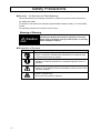
Safety Precautions
z Symbols
for Safe Use and Their Meanings
This manual employs the following indications or symbols for points to note for the user to
use Model KM1 safely.
The points to note shown here indicate important details related to safety. You must adhere
to them.
The following indications and symbols can be shown.
Meaning of Warning
Caution
Handling this product incorrectly is dangerous. This may
lead to mild to moderate severity ended injuries, or this may
lead to damage to objects
z Explanation of Symbols
Symbol
Meaning
z Prohibition of assembly
Notice of prohibition indicated when disassembly of equipment may
cause an electric shock or injuries.
z General mandatory notice
Indication for instructing behaviors of unspecified general users not
specified.
z Caution, electricity
Notice for giving attention about the possibility of electric shock under
a specific condition.
z Caution, explosion risk
Wrong use may cause an explosion.
IV
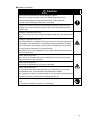
z Display of warning
Caution
Ignition may occur and this may cause damage to objects.
Make sure you tighten terminal screws with standard tightening torque.
Recommended tightening torque of terminal screw: 0.69 to 0.88 Nxm
After the screw is tightened, ensure that it is not tilted.
Explosion may cause a medium or minor degree of injuries or physical loss or
damage. Do not use the product at a place where it is exposed to flammable or
explosive gas.
Breakage or explosion may occur.
When using the product, put the supply voltage and load in the specified or rated
range.
Breakage or explosion may occur.
The portion between the voltage input circuit and the CT secondary side circuit is
not insulated. If the dedicated CT is grounded, the portion between the voltage
input circuit and the CT secondary circuit is short-circuited due to wrong wiring.
Do not ground the dedicated CT to prevent failures.
This product, which uses a dedicated CT, can make normal measurements with
the CT not grounded.
Electric shocks may occur.
When the CT is connected, disconnect voltage inputs connected to the power
supply and system of the main body.
Electric shocks may occur.
When power is distributed, do not touch the terminals.
Electric shocks may occur.
For the primary side electric wire where the CT is clamped, be sure to use a
covered electric wire, which has been at least basically insulated.
When clamping is done for a conductive object, such as bus bar, ensure the basic
insulation, at least, by covering it with insulating material, etc.
Electric shocks, minor degree of injuries, ignition, or equipment failures may
occur.
Do not perform assembling, repairing, or remodeling.
V
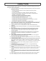
Safety Points
To prevent operation failure or malfunction of the product, and prevent affecting performances
and function, observe the following.
1) Prevent the operation and storage (including transportation) of the product under the
following environment.
x In a place with large vibrations or which is greatly influenced by shocks
x In an unstable place
x In a place at a temperature or humidity outside the specification range
x Places with large changes in temperature and humidity, or where there is a
possibility of condensation or freezing
x Place where the product is exposed to direct sunlight.
x Outdoors or in a place directly exposed to wind and rain
x In a place affected by static electricity or noise
x In a place where the product is exposed to oil or salt water.
x In a place where corrosive gas (sulfurizing gas, ammonia gas, etc.) exists
x In a place with a lot of dust or iron powder
x In a place that is affected by electrical fields or magnetic fields
2) When installing the DIN rail with screws, prevent looseness. Securely install the DIN
rail on the main body. Looseness, if any, causes the DIN rail, the main unit of the
product or wiring to come off due to vibration, impact, etc.
3) Use the DIN rail of 35 mm in width (Model PFP-50N/-100N manufactured by
OMRON).
4) When wiring on the main body of the product, use a crimp-style terminal suitable for
M3.5 screw.
5) Before distributing energy, confirm that the specification and wiring are correct.
6) Before performing operation and maintenance, fully understand the instruction
manual. Not doing so may result in electric shock, faults, accidents, injury, or
incorrect operation.
7) For the worker to turn OFF the power supply, install a switch or a circuit breaker
matching the requirements of IEC60947-1 and IEC60947-3, and display it
appropriately.
8) When setting the equipment, fully understand the manual.
9) When installing this product, keep it away as far as possible from the equipment
generating strong high-frequency noise or surge.
10) Touch this product after taking measures against static electricity, such as touching
metal that has been earthed.
11) To prevent inductive noise, isolate the wiring on the main body from the power line of
high voltage or large current. In addition, avoid wiring in parallel to or shared with
power lines. Use of a different conduit, a duct, or a shield line is an effective method
of wiring.
12) Do not install this product close to heating equipment (equipment having a coil,
winding wire, etc.).
13) Take measures to prevent metal, conductive wire, or chip generated during
processing from entering this product.
14) Do not use thinner-type products when cleaning. Use a commercially-available
alcohol.
15) Use an appropriate electrical power source and wiring to supply a power voltage and
in/output to this product. Otherwise, failures, burnout, or electric shocks may be
caused.
16) When installing the product on a wall, use screws to prevent looseness. Looseness,
if any, causes the main unit of the product or wiring to come off due to vibration,
impact, etc.
17) When multiple units are used, slide a horizontal connection hook until it is clicked.
18) When installing the product in a DIN rail, slide the DIN hook until it is clicked.
VI
19) Use the dedicated CT and dedicated CT cable specified by OMRON.
Split type
Through
type
Model KM20-CTF-5A
Model KM20-CTF-200A
Model KM20-CTF-50A
Model KM20-CTF-400A
Model KM20-CTF-100A
Model KM20-CTF-600A
Model KM20-CTB-5A/50A
Dedicated CT cable: Model KM20-CTF-CB3 (3 m)
20) It is not available for measuring inverter secondary side measurements.
21) Do not block the air ventilation holes of this product and the area surrounding them,
in order to allow heat to be emitted.
22) Check the terminal number and carry out wiring correctly. Connect nothing to the
terminals not used.
23) This product is a "Class A" (industrial environment product). Using this product in a
residential setting environment may cause electronic jamming. In that case,
appropriate measures for electronic jamming must be taken.
24) Use the dedicated CT in a low voltage circuit of 600 V or less.
Requests for Installation
z To use this product for a long time
Use this product within the following temperature and humidity ranges.
Temperature: -10 to +55°C (without freezing and condensation)
Humidity: 25 to 85%RH
Not the temperature around the board but the temperature around this product must be within
55°C.
This product has a product service life that is determined by the service life of electronic parts
used inside. The service life of parts depends on the ambient temperature. As the ambient
temperature is higher, the service life is shorter, and as the temperature is lower, the life is
longer. Therefore, lowering the internal temperature of the product can lengthen its life.
Installing more than one Model KM1 close to each other or by arranging them in the up-down
direction requires the consideration of forced cooling by, e.g., sending air to the products
through a fan.
z To achieve resistance against peripheral noise
To prevent inductive noise, isolate the wiring in the terminal block of the main body from the
power line of high voltage or large current. In addition, avoid wiring in parallel to or shared
with power lines. Use of a different conduit, a duct, or a shield line is an effective method of
wiring.
Attach a surge absorber or a noise filter to the equipment (equipment having inductance
components in particular, e.g., motor transformer, solenoid, and magnet coil) generating
noise around the product.
When installing this product, keep it away as far as possible from the equipment (high
frequency welder, high frequency machine, etc.) generating strong high-frequency noise or
surge.
VII
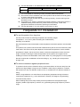
Precautions for Use
1)
2)
3)
4)
5)
Make correct settings according to the targets to be monitored.
Do not hold and pull a cable.
This product is not a specific measuring instrument that has passed an examination
performed pursuant to the Measurement Act.
This product is not available to issue a certificate for electric energy.
When discarding this product, appropriately treat it as an industrial waste.
If this product is used in the environment of overvoltage category III, install a varistor
between lines on the power supply of this product/outside voltage measurement
input.
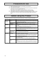
Before Using this Product
Referring to the instruction manual that came with this product, confirm the relevant items below.
When
When the
product is
purchased
At the time of
installation
At the time of
wiring
Working
environment
VIII
Confirmation item
Appearance of the
product
Confirmation contents
After purchasing the product, check the packing box for dents.
If the inside has been damaged, measurements cannot be made properly
depending on the point of damage.
Product format and Confirm that the specification of the purchased product matches that
specification
desired.
Installation place of When installing the product, allow the heat to radiate by preventing
the product
covering the area around the product. Do not cover the vent holes of the
main body.
When installing the products close to each other, consider forced cooling,
such as by sending air to the products through a fan.
Wiring of terminals When tightening a screw, be careful to prevent giving excessive stress.
In addition, tighten the screw to the specified torque (0.69 to 0.88 N・m)
and confirm that it does not loosen.
Confirming the polarity of each terminal, perform wiring correctly.
Power
Perform correct wiring of power supply/voltage input. Incorrect wiring may
supply/voltage
cause the destruction of the internal circuit.
input
Ambient
The working ambient environment of this product ranges from -10 to
temperature
+55°C (without condensation or freezing).
To make the service life longer, install the product in such a way that the
ambient temperature becomes as low as possible. If the temperature is
high, consider forced cooling by a fan.
Vibration/impact
Confirm that the vibration/impact of the installation environment satisfies
the specified standard.
(If the product is installed near a conductor, keep it away as far as
possible from the conductor, because vibration/impact is applied to it.)
Entry of foreign
Do not install the product in a place where liquid or foreign matter may
matter
enter it.
If corrosive gas, such as sulfur or chlorine, is generated, the environment
should be improved by removing the generation source or by installing a
fan.
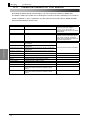
Relevant Manuals
Man. No.
SGTE-717
Model
Model
KE1-
-FLK
Model KE1-
SGTE-718
Model KE1-DRT-FLK
SGTE-719
Model KM1/KE1
GAMS-010
Model KM1/KE1
Manual Name
Model KE1
User’ s Manual for
Smart Measurement
and Monitoring
Instrument
Model KE1
User’ s Manual for
Device Net
Communication Unit
Model KM1/KE1
Smart Power Monitor
Communication Manual
for Smart Measurement
and Monitoring
Instrument
KM1/KE1-Setting
User’ s Manual
Details
Describes the overview,
characteristics, functions and
settings of Model KE1
Describes the functions and
settings of DeviceNet
Communication Unit
Describes the details of
communication for the Model
KM1/KE1 series
Describes how to use setting
tools for the Model KM1/KE1
series and the setting
procedure.
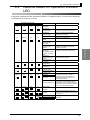
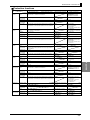
Abbreviation
Abbreviation
PMU1A (Electric
power)
PMU2A (Power
Two-System)
EMU8A
(Pulse/temperature)
PGR1C
(Power/Earth
leakage)
PVS1C (Power
instantaneous
voltage drop)
VSU1B
(Instantaneous
voltage drop)
VAU1B
(voltage/current)
CTD8E (CT
expansion)
ZCT8E (ZCT
expansion)
DRT (DeviceNet)
*1
*2
*3
*4
Format
Model
KM1-PMU1A-FLK
Model
KM1-PMU2A-FLK
Model
KM1-EMU8A-FLK
Model
KE1-PGR1C-FLK
Name
Power Measuring Unit
Power Two-System
Measurement Unit
Pulse/Temperature Input
Unit
Power/Earth Leakage
Monitor Unit
Functional slave
(*2)/(*3)
Measurement master
(*1) (*2) (*3)
Model
KE1-PVS1C-FLK
Power/Instantaneous
Voltage Drop Monitoring
Unit
Instantaneous Voltage
Drop Monitoring Unit
Functional slave
(*2) (*3) (*4)
Model
E1-VSU1B-FLK
Model
KE1-VAU1B-FLK
Model
KE1-CTD8E
Model KE1-ZCT8E
Voltage/Current
Monitoring Unit
CT Expansion Unit
ZCT Expansion Unit
Model
KE1-DRT-FLK
DeviceNet
Communication Unit
Unit type
Measurement master
(*1) (*3)
CT expansion slave
(*2) (*4)
Communication slave
(*2) (*4)
Slaves can be connected.
Can be connected to the measurement master.
Can be operated independently.
Product of KE1.
IX
For the connection, refer to pages 1 to 9.
In addition, for the combinations, refer to Page A-19.
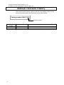
Manual Revision History
The manual revision symbol is given at the end of the catalog number on the
front cover and the bottom left of the back cover of the manual.
Catalog number KANC-701A
Revision symbol
Revision
symbol
A
B
X
Date of revision
May 2012
June 2012
Reason for revision/ pages revised
Initial version
Correction of error in writing
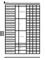
Table of Contents
INTRODUCTION ..................................................................................... I
Items on which you Agree by Using this Product.................................. II
Safety Precautions.................................................................................IV
Safety Points ..........................................................................................VI
Requests for Installation .......................................................................VII
Precautions for Use .............................................................................VIII
Before Using this Product....................................................................VIII
Relevant Manuals ..................................................................................IX
Abbreviation ...........................................................................................IX
Manual Revision History.........................................................................X
Table of Contents ...................................................................................XI
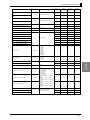
Chapter 1
1.1
Overview ..........................................................................1-1
Main features and functions ............................................................................1-2
Main features ..............................................................................................................1-2
Main functions.............................................................................................................1-3
1.2
Name and function of each part ......................................................................1-6
Name of each part ......................................................................................................1-6
Explanation of the display unit....................................................................................1-7
Setting switch..............................................................................................................1-8
1.3
System configuration.......................................................................................1-9
Model kind...................................................................................................................1-9
Configuration............................................................................................................ 1-10
1.4
Format standard ............................................................................................1-13
Format standard ...................................................................................................... 1-13
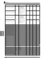
Chapter 2
2.1
Preparation ......................................................................2-1
Flow before use ...............................................................................................2-2
Setting example..........................................................................................................2-3
2.2
Installation........................................................................................................2-6
External Dimensions (unit: mm).................................................................................2-6
Connection method ....................................................................................................2-7
Installation procedure .................................................................................................2-9
2.3
Installation of dedicated CT...........................................................................2-12
Wire connection and installation of dedicated CT .................................................. 2-13
2.4
Input/output configuration and example of wiring diagram...........................2-14
Model KM1-PMU1A-FLK ........................................................................................ 2-14
Model KM1-PMU2A-FLK ........................................................................................ 2-16
Model KM1-EMU8A-FLK ........................................................................................ 2-19
Model KE1-CTD8E.................................................................................................. 2-20
XI
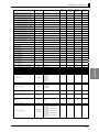
2.5
Wiring............................................................................................................. 2-25
Requests for wiring .................................................................................................. 2-25
Wiring ....................................................................................................................... 2-25
Chapter 3
Functions .........................................................................3-1
3.1
List of functions............................................................................................... 3-2
3.2
Basic functions................................................................................................ 3-3
Applicable phase wire............................................................................................... 3-3
Synchronization selection for measuring block ...................................................... 3-3
Dedicated CT type .................................................................................................... 3-3
VT ratio....................................................................................................................... 3-4
CT ratio ...................................................................................................................... 3-4
Low-cut function........................................................................................................ 3-4
Average count ........................................................................................................... 3-5
Logging function........................................................................................................ 3-5
Signal detection ........................................................................................................ 3-5
Measurement function .............................................................................................. 3-6
3.3
Output function................................................................................................ 3-9
Output terminal 1/output terminal 2/output terminal 3 function setting ............... 3-9
Integrated power amount pulse output ................................................................. 3-10
Phase-sequence ..................................................................................................... 3-11
Alarm output ............................................................................................................ 3-12
3.4
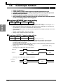
Event input function...................................................................................... 3-16
Event input NPN/PNP input mode setting ........................................................... 3-16
Event input N-O/N-C input mode setting ............................................................. 3-16
Pulse entering count ............................................................................................... 3-17
ON time of pulse enter ........................................................................................... 3-17
Function using event input..................................................................................... 3-17
3.5
3-STATE function ......................................................................................... 3-18
3-STATE target ....................................................................................................... 3-18
3-STATE HIGH threshold/3-STATE LOW threshold ........................................... 3-20
3-STATE hysteresis................................................................................................ 3-20
3.6
Other functions ............................................................................................. 3-21
Time ......................................................................................................................... 3-21
Initialization ............................................................................................................. 3-21
Chapter 4
XII
Troubleshooting ..............................................................4-1
4.1
Flow of troubleshooting.................................................................................. 4-2
4.2
Assume based on operation indicator LED ................................................. 4-3
4.3
Assume based on the status......................................................................... 4-4
4.4
Assume based on phenomena ..................................................................... 4-5
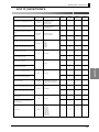
Appendix.............................................................................................. A-1
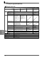
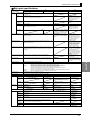
Product specifications ................................................................................................. A-2
Rating of main unit ................................................................................................... A-2
Main part specifications........................................................................................... A-3
Protection functions ................................................................................................. A-5
Accessories............................................................................................................... A-6
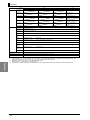
Dedicated CT ............................................................................................................... A-7
Specification.............................................................................................................. A-7
External dimensions (unit: mm) .............................................................................. A-7
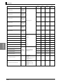
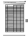
List of parameters........................................................................................................ A-9
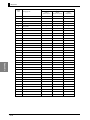
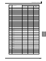
List of data logging items .......................................................................................... A-15
Model KM1/KE1 combination list ............................................................................. A-19
XIII
Chapter 1.
Overview
Chapter 1.
1.1
1.2
1.3
1.4
1-1
Overview............................................................................ 1-1
Main features and functions ................................................................................... 1-2
■
Main features ................................................................................................ 1-2
■
Main functions ............................................................................................... 1-3
● Function by unit ......................................................................................... 1-3
● Output function .......................................................................................... 1-3
● Input function ............................................................................................. 1-5
● Communication function ............................................................................ 1-5
● Logging function of measurement data ..................................................... 1-5
Name and function of each part ............................................................................. 1-6
■
Name of each part ........................................................................................ 1-6
■
Explanation of the display unit ...................................................................... 1-7
■
Setting switch ................................................................................................ 1-8
● How to use setting switches ...................................................................... 1-8
System configuration.............................................................................................. 1-9
■
Model kind..................................................................................................... 1-9
■
Configuration............................................................................................... 1-10
● Multiple-unit connection........................................................................... 1-10
● Minimum configuration ............................................................................ 1-11
● Maximum configuration ........................................................................... 1-11
● Multiple-system configuration.................................................................. 1-12
Format standard ................................................................................................... 1-13
■
Format standard.......................................................................................... 1-13
0BOverview
1.1
Main features and functions
Overview
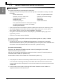
Main features
This section describes the main features fro Model KM1.
•
Models providing the following functions are lined up and are selectable according to intended
end-usage.
Power measurement
Power Two-System Measurement
Detection of over or under current
Detection of over/under voltage
Temperature measurement
Event input
Pulse input count
Pulse output
ON time of pulse input
Simple measurement
CO2 emissions/conversion to electric power charge
3-STATE function (power, current, and voltage)
Reverse phase detection
Power measurements of two different systems insulated each other can be made using a unit.
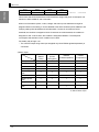
The installed logging function allows the user to select eight cycles (5 min, 10 min, 30 min, 1
hour, 2 hours, 6 hours, 12 hours, 24 hours) available for saving data.
Two types of communication protocol, CompoWay/F (*1) and Modbus (RTU) (*2), can be
supported by one unit.
Conforms to the safety standard (EN/IEC).
[Connection of multiple units (PMU1A (electric power)/PMU2A (power two-system) + EMU8A
(pulse/temperature))]
・ According to the event input of EMU8A (pulse/temperature), the total power consumption
measured with PMU1A (electric power) and PMU2A (power two-system) can be classified to the
three states: HIGH state, MIDDLE state, and LOW state. (3-STATE function)
[Connection with Model KE1]
Connection with Model KE1-CTD8E can expand current CT, allowing the user to make
measurements at 36 points maximum.
After this, this manual also describes the expansion function of current CT when this product is
connected to KE1-CTD8E (CT expansion unit).
For Model KE1-CTD8E, refer to "Model KE1 User's Manual" (SGTE-717).
*1 CompoWay/F is a unified communication procedure within Omron’s generic serial communication.
It has commands conforming to the time-proven FINS in the unified frame format and Omron's
programmable controller, making easy the communication between the personal computer and the
components.
*2 Communication control system conforming to RTU Mode of Modbus Protocol. Modbus is a
registered trademark of Schneider Electric.
1-2
1.4
Format standard
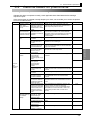
Main functions
This section describes main functions of Model KM1.
Overview
z Function by unit
PMU1A (Electric power)
: Provides the power measurement function and 3-STATE
function.
PMU2A (Power two-system) : Provides the power measurement function and 3-STATE
function. Two-system measurements can be done.
EMU8A (Pulse/temperature) : Has an event input and temperature input. It provides
temperature measurement function.
CTD8E (CT expansion)
: CT can be expanded to perform power and current multi-circuit
measurements.
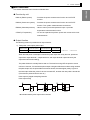
z Output function
The following function is provided as an output function.
1) Total power consumption pulse output
PMU1A
(Electric power)
PMU2A
(Power two-system)
EMU8A
(Pulse/temperature)
CTD8E
(CT expansion)
{
{
×
×
{: With function
×: Without function
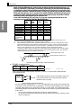
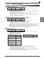
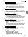
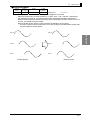
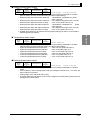
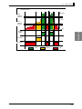
When the total power consumption reaches the pulse output unit set by the user, pulses are
output from output terminal 1, output terminal 2, and output terminal 3 (terminal set by the
output terminal function setting).
The pulse ON time is normally fixed to 500 ms. The time for turning OFF the pulse is 100 ms
minimum. However, if it reaches the pulse output unit again within 600 ms after having reached
the pulse output unit, the pulse ON time becomes shorter, because higher priority is given to
the next output. After that, pulse of 100 ms is turned OFF, and then the next pulse is turned ON.
(The minimum pulse ON time is 100 ms.)
Pulse output is judged at sampling intervals.
Pulse output timing
100ms
500ms
100ms
500ms
500ms
100ms
100ms
500ms
500ms
*▼ indicates that the pulse output unit is reached.
1-3
0BOverview
2) 3-STATE output
Overview
PMU1A
(Electric power)
PMU2A
(Power two-system)
EMU8A
(Pulse/temperature)
CTD8E
(CT expansion)
{
{
×
×
{: With function
×: Without function
This function sets HIGH threshold and LOW threshold to assign total power consumption and
total time to HIGH, MIDDLE, and LOW states.
When one of the electric power, current, voltage, and event input is selected as a target for
judgment based on the setting, it can be classified to the three conditions (HIGH, MIDDLE, and
LOW) by setting HIGH threshold and LOW threshold. If a value is more than the HIGH
threshold, the condition is assigned to HIGH. If less than the LOW threshold, the condition is
assigned to LOW. In other cases, the condition is assigned to MIDDLE. The total power
consumption and total time in each condition can be read.
For details, refer to Page 3-18.
* The 3-STATE output using event input is applied only when EMU8A (pulse/temperature) is
connected.
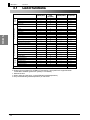
3) Alarm output
PMU1A
(Electric
power)
PMU2A
(Power
two-system)
Active power alarm
{
{
×
{
Over current alarm
{
{
×
{
Under current alarm
{
{
×
{
Over voltage alarm
{
{
×
×
Under voltage
alarm
{
{
×
×
Power factor alarm
{
{
×
{
Reactive power
alarm
{
{
×
{
Temperature alarm
×
×
{
×
Reverse phase
alarm
{
{
×
×
EMU8A
CTD8E
(Pulse/temperature) (CT expansion)
O: With alarm output
X: Without alarm output
1-4
1.4
Format standard
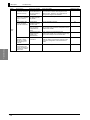
z Input function
The input functions include the following functions.
Overview
•
Event input 7 points
PMU1A
(Electric power)
PMU2A
(Power two-system)
EMU8A
(Pulse/temperature)
CTD8E
(CT expansion)
×
×
{
×
{: With function
X: Without function
A pulse output from external equipment is counted as an input pulse.
Using the event input can achieve the 3-STATE function, whose target for judgment includes
the following: a power original unit calculated by dividing the total power consumption, which is
measured with PMU1A (electric power) and PMU2A (power two-system), by the total value of
two input count numbers (event inputs 1 and 2, event inputs 3 and 4, and event inputs 5 and 6),
a pulse input ON time measured by using OR judgment, and an event input.
The power original unit and the pulse input ON time are used for measurement of tact power in
a production line and for calculation of operating time of equipment, respectively.
*
The 3-STATE function using power original unit and event input are available only when the
product is connected to PMU1A (electric power), PMU2A (power two-system).
z Communication function
The communication function using CompoWay/F and Modbus (RTU) is available.
z Logging function of measurement data
PMU1A
(Electric power)
PMU2A
(Power two-system)
EMU8A
(Pulse/temperature)
CTD8E
(CT expansion)
{
{
{
U
{: With function
U: Backup at intervals of 5 min and alarm history only.
Model KM1 has a data logging function. Log data is divided into the three types: data that is backed
up every 5 min, data that is backed up at arbitrary timing (5 min, 10 min, 30 min, 1 hour, 2 hours, 6
hours, 12 hours, or 24 hours), and alarm history that is backed up when an alarm is generated.
1) Data that is backed up every 5 min
This data includes the following items.
Total active power consumption, total regenerated energy, and total reactive power
3-STATE HIGH total power consumption, 3-STATE MIDDLE total power consumption,
3-STATE LOW total power consumption
3-STATE HIGH total time, 3-STATE MIDDLE total time, 3-STATE LOW total time
Pulse input ON time, pulse input count
2) Data that can be saved as log data at arbitrary timings
Log data is saved in conjunction with the time of the main body.
For the items, refer to "List of log data to be saved" on Page A-15.
3) Alarm history
Histories of alarms generated in the past can be confirmed via communication.
Data is saved every 5 min.
For details, refer to Page 3-12.
1-5
0BOverview
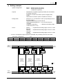
1.2
Name and function of each part
Overview
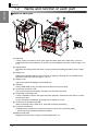
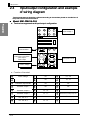
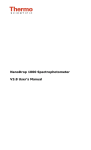
Name of each part
7
6
1
6
1
2
8
10
3
4
5
9
7
[1] DIN hook
A hook, which is mounted in each of the upper and lower parts of the main body, is used to
install the product in the DIN rail or on a wall. For the installation procedure, refer to Page 2-9 to
2-11.
[2] Setting switch
DIP switch and rotary switch are used. For the functions and setting procedure, refer to Page
1-8.
[3] Display unit
Displays the operating status of the main body by lighting or blinking LED. For details on the
function of each LED, refer to Pages 1-7 to 4-3.
[4] Display cover
This cover protects the display unit and USB port.
[5] USB port
Insert a USB cable to carry out USB communication with the main body.
[6] Connection connector cover
This cover protects the connection connector (on the main body side).
[7] Horizontally connecting hook
A hook is installed in each of the upper and lower positions. These hooks are used to connect
units to each other.
For the connection procedures ([7] to [9]), refer to Pages 2-7 to 2-8.
[8] Connector (on the main body side)
When connecting units to each other, insert the connector (accessory).
[9] Connector (accessory)
Inserted into the connector to connect connectors to each other (main body side).
* It does not come with the measurement master.
[10]Rating name plate
Displays the model name, ratings, terminal assignments, etc.
1-6
1.4
Format standard
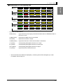
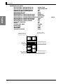
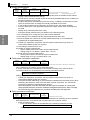
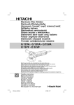
Explanation of the display unit
Overview
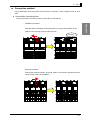
PMU1A
(Electric
(電力) power)
PWR
ALM
CT1
CT2
CT3
CONN
COMM
OUT1
OUT2
OUT3
PWR
ALM
CT1
CT2
CT3
CONN
COMM
OUT1
OUT2
OUT3
PWR
ALM
EV1
EV2
EV3
EV4
CONN
COMM
EV5
EV6
EV7
TH
PWR
ALM
CT1
CT2
CT3
CT4
CONN
COMM
CT5
CT6
CT7
CT8
PMU2A
(Power )
(電力2系統
two-system)
CT4
EMU8A
(Pulse/
(パルス/温度
)
temperature)
CTD8E
(CT
expansion)
(CT増設)
*
Explanation of abbreviations
PWR (Green) :
Lights when the power supply is turned ON. Blinks when an EEPROM, RAM, or
RTC error occurs.
CONN (Yellow) :
Lights when multiple units are connected.
ALM (Red)
Lights when an alarm is output.
:
COMM (Yellow) :
Lights when RS-485 or USB communication is carried out.
CT (Yellow)
:
Corresponding LED lights at the time of CT input.
EV (Yellow)
:
Corresponding LED lights at the time of event input.
OUT (Yellow)
:
Corresponding LED lights at the time of output.
TH (Yellow)
:
Lights at the time of thermistor input.
*
Normal and abnormal states are displayed by combining above LEDs that lights up or blink.
For details, refer to Page 4-3.
1-7
0BOverview
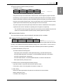
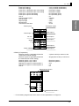
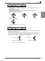
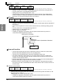
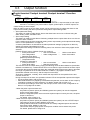
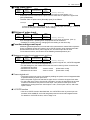
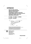
Setting switch
DIP switches and a rotary switch are used for setting switches. DIP switches select communication
used to identify the units. (A rotary switch is used only for functional slaves and CT extension slaves.
The slave for measurement master will have a fixed ID of 0. )
DIP switch
No.1 ⇒ Idle
No.2 ⇒ Selection of communication protocol:
OFF CompoWay/F
ON
ON Modbus
•
Rotary switch
Set a slave ID.
:
*
901
For slave units, set slave ID of 1-4. For EMU8A
(pulse/temperature) to be used for the 3-STATE
2 3
7 8
Do not use the IDs of 0 and 6-9. )
function or power original unit, however, set slave ID
456
Overview
protocols, while a rotary switch sets a slave ID. When multiple units are connected, slave IDs are
to 5.
*
If multiple units are connected, set slave IDs in a way
to avoid duplicates.
z How to use setting switches
1-8
Be sure to use the switch when the power supply is turned OFF. The settings will be read
only when connected to a power supply and any change made during power distribution will
not be reflected. To make change, switch off the power first and change the settings. And
switch on the power again.
When selecting a switch, set it to the specified position securely by using a small flat-head
screwdriver.
1.4
1.3
Format standard
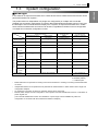
System configuration
In this manual, an object that has been set in a state where various measurements and monitor can be
performed is defined as "System."
This product allows an independent unit (single-unit configuration) or multiple units connected
(multiple-unit connection configuration) to perform data measurements and status monitor. From here,
the description of this manual therefore employs as "a system" an object that has been set in a state
where various measurements and monitor can be done, regardless of whether one-unit configuration
or multiple-unit connection configuration is used.
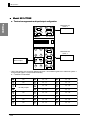
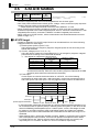
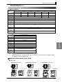
Functional slave
CT extension slave
PMU1A (Electric power)
Measurement master
PMU2A (Power
two-system)
EMU8A
(pulse/temperature)
CTD8E (CT expansion)
Master behavior
{
{
×
×
Independent behavior
{
{
U
×
CT expansion
{
{
×
×
{
{
×
{
{
{
×
{
Voltage
{
{
×
×
Temperature
×
×
{
×
Pulse
×
×
{
×
Reverse
{
{
×
×
Measurement (Monitoring) function
Electric
power
Electric
currents
phase
Power voltage
AC100~240V 50/60Hz
None (supplied from
measurement master)
O: Enabled (with)
X: Disabled (without)
U: Limited in part
*
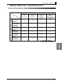
Master behavior is an operation for setting connections with slaves or sending or receiving measurement data
on slaves.
*
Independent behavior is an operation that is performed for measurements or status monitor with a single unit
configuration adopted.
*
*
CT expansion is a function by which CT extension slaves can be connected.
EMU8A, which adopts one-unit configuration, cannot perform 3-STATE classification function or calculation of
power original unit.
(The 3-STATE classification function and calculation of power origin unit are available only when the
configuration of connection with the measurement master is adopted.)
1-9
Overview
Model type
0BOverview
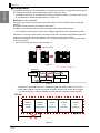
Configuration
Overview
This product is used in the unit independent or multiple-unit connection configuration (connection of
the measurement master with functional slave and CT extension slave).
* Available combinations of connections have been prepared for models. For details, refer to "List
of Combinations in Model KM1/KE1 Series" on Page A-19.
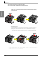
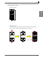
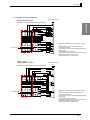
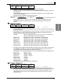
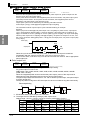
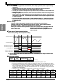
z Multiple-unit connection
Connecting the measurement master to a functional slave or a CT extension slave can expand
functions.
(Functional slaves cannot be connected to each other.)
In addition, a CT extension slave must be connected to the measurement master.
* A CT extension slave behaves when power voltage is applied from the measurement master.
Connection of units uses a horizontally connecting hook and a connector. Appropriately insert the
connector to send and receive data between the units and to apply power voltage.
Inappropriate insertion may cause problems, such as data communication error and power failure
in the unit. (Figure 2)
* For the connection procedures, refer to Page 2-7.
Attach the connector.
Figure 1
Occurrence of communication errors
Master/slave
Power
voltage
Measurement data
NG
OK
Measurement data
Figure 2
Note: Power voltage is applied to the CT extension slave only.
If settings of a functional slave or a CT extension slave are changed directly not via the
master when multiple units are connected, supply the power to the system all over again.
* As shown in Figure 3, prevent multiple wiring for RS-485 connection within a system.
RS-485
PMU1A
(Electric
power)
EMU8A
(Pulse/
temperature)
CTD8E
CTD8E
CTD8E
(CT
expansion)
(CT
expansion)
(CT
expansion)
1 System
Figure 3
1-10
1.4
Format standard
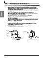
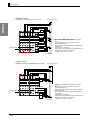
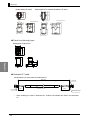
z Minimum configuration
•
A measurement master or functional slave can be used independently.
Overview
*
A single unit of CT expansion slave is not available.
Measurement master
functional slave
CTD8E (CT expansion)
DRT (DeviceNet)
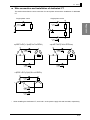
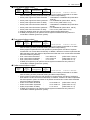
z Maximum configuration
•
One measurement master can connect to a maximum of four units, including functional slave
and CT extension slave units. A communication slave can connect to only one unit.
Communication
slave
Communication
slave
Measurement
master
x
x
Functional slave
CT extension slave
Measurement
master
Only one communication slave
Only one measurement master
・
Functional slave
・
CT extension slave
A maximum of four units, including functional
slave and CT extension slave units
* For the communication slave (DRT (DeviceNet)), refer to "Model KE1 User's Manual"
(SGTE-717) and "Model KE1 User's Manual for DeviceNet Communication Unit
(SGTE-718).
1-11
0BOverview
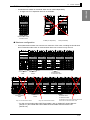
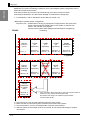
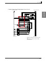
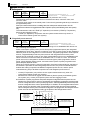
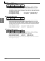
z Multiple-system configuration
Overview
Model KM1 is a system containing a maximum of six units. Multiple-system configuration can be
made via RS-485 communication.
Connecting masters to each other via RS-485 wiring can achieve various functions.
Connecting to Model KE1 can detect earth leakage or instantaneous voltage drop.
*1. For Model KE1, refer to "Model KE1 User's Manual" (SGTE-717).
¡ Example of multiple-system configuration
Purpose of use : Classification of energy by equipment of single-phase 3-wire system line.
Power measurements by single phase 3-wire system, 3-phase 3-wire
system, and 3-phase 4-wire system
3-phase 3-wire system earth leakage and instantaneous voltage drop
monitoring.
RS-485
PMU2A
(Power-two
system)
Unit No.: 01
CTD8E
(CT
expansion)
CTD8E
(CT
expansion)
CTD8E
(CT
expansion)
EMU8A
(Pulse/temp
erature)
Slave ID: 1
Unit No.: 02
Slave ID: 2
Unit No.: 03
Slave ID: 3
Unit No.: 04
Slave ID: 5
Unit No.: 05
1 System
PGR1C
(Electric
power/earth
leakage)
Unit No.: 06
CTD8E
(CT
expansion)
VSU1B
(Instantaneo
us voltage
drop)
ZCT8E
(ZCT
expansion)
Slave ID: 1
Unit No.: 07
Slave ID: 2
Unit No.: 08
Slave ID: 3
Unit No.: 09
1 System
VSU1B
(Instantaneo
us voltage
drop)
Slave ID: 2
Unit No.: 08
1 System
*2.
*3.
*4.
*5.
1-12
* If it is included in the system above, inter-unit communication is
carried out. This makes communication slow.
This means that using it as a different system makes
communication faster.
Set slave IDs in a way to avoid duplicates within the same system.
Make sure the communication protocol matches across the entire systems.
Set unit numbers in a way to avoid duplicates across the entire systems.
Within a system where multiple units are connected, do not use RS-485 wiring for multiple
connections.
1.4
1.4
Format standard
Format standard
Overview
Format standard
K
1-
-FLK
[1] [2] [3]
[4]
[5] [6]
[7]
[1] K
:
Product of measurement monitor
[2] M
:
Smart Power Monitor
E
:
Smart Measurement and Monitoring Instrument
[3] 1
:
Series No.
[4]
:
Unit type
PMU Power measurement unit
EMU Pulse/temperature input unit
CTD CT Expansion Unit
[5]
:
Number of input circuits
[6]
:
A NPN transistor X 3 outputs
E 1a relay X 1 output
[7] FLK
:
With communication function
1-13
Chapter 2.
2.1
Preparation
Flow before use ................................................................................ 2-2
■ Setting example .............................................................................................. 2-3
● Setting list of units ................................................................................... 2-4
2.2
Installation ......................................................................................... 2-6
■ External dimensions (unit: mm) ...................................................................... 2-6
■ Connection method......................................................................................... 2-7
● Horizontally connecting hook .................................................................. 2-7
● Connector................................................................................................ 2-8
■ Installation procedure ..................................................................................... 2-9
● Installation of DIN rail.............................................................................. 2-9
● Installation on a wall.............................................................................. 2-11
2.3
Installation of dedicated CT ............................................................ 2-12
2.4
Input/output configuration and example of wiring diagram ............ 2-14
■ Wire connection and installation of dedicated CT ........................................ 2-13
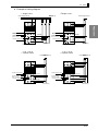
■ Model KM1-PMU1A-FLK .............................................................................. 2-14
● Terminal arrangements and input/output configuration........................ 2-14
● Function of terminal .............................................................................. 2-14
● Example of wiring diagram.................................................................... 2-15
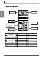
■ Model KM1-PMU2A-FLK .............................................................................. 2-16
● Terminal arrangements and input/output configuration........................ 2-16
● Function of terminal .............................................................................. 2-16
● Example of wiring diagram.................................................................... 2-17
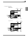
■ Model KM1-EMU8A-FLK .............................................................................. 2-19
● Terminal arrangements and input/output configuration........................ 2-19
● Function of terminal .............................................................................. 2-19
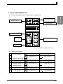
■ Model KE1-CTD8E ....................................................................................... 2-20
● Terminal arrangements and input/output configuration........................ 2-20
● Function of terminal .............................................................................. 2-20
● Example of wiring diagram.................................................................... 2-21
2.5
Wiring .............................................................................................. 2-25
■ Requests for wiring ....................................................................................... 2-25
■ Wiring............................................................................................................ 2-25
● Power voltage ....................................................................................... 2-25
● USB port................................................................................................ 2-26
● Input voltage.......................................................................................... 2-26
● CT input................................................................................................. 2-27
● RS-485 communication......................................................................... 2-28
● Output.................................................................................................... 2-29
● Event input ............................................................................................ 2-29
0BPreparation
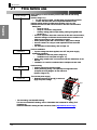
2.1
Flow before use
Initial Settings
Preparation
Installation
Wiring
Power ON
Make settings of communication protocol and slave ID with setting
switches.
(Refer to Page 1-8.)
*
For the units to be used, use the same communication protocol.
*
Confirm that slave IDs are not duplicated between units.
Initialize setting values via USB communication. (Unit no. XX)
Initialize the units via USB communication or RS-485 communication.
Setting item
x
Setup of unit no.
x
Setup of connection configuration
x
Arbitrary setting (alarm output setting, setting of log data to be
saved, etc.)
* Since CT expansion slave has a terminal for RS-485 communication,
make the settings via RS-485 communication that is carried out via
USB communication or the measurement master.
* When performing RS-485 communication, apply power voltage.
* Set unit numbers in a way to avoid duplicates across the entire
systems.
* For examples of initial setting, refer to Page 2-3.
Perform installation
* If power voltage has been applied, turn OFF the power supply.
Installation procedure
x
Installation of DIN rail (refer to Page 2-9)
x
Installation on a wall (refer to Page 2-11)
* When using multiple units, connect them and then install them in the
DIN rail.
* Installation on a wall is not allowed when multiple units are used.
Perform wiring.
* Perform wiring from the lower stage.
* When performing wiring, use input/output configuration and
examples of wiring diagram for the reference.
(Refer to Page 2-14.)
Turn ON the power supply.
* Between terminals [1] and [2] in each unit,
apply the power voltage.
Upp
Low
* For the setting, use KM1/KE1-Setting.
For how to use KM1/KE1-Setting, refer to "KM1/KM1 User's Manual for Setting Tool"
(GAMS-010).
Download KM1/KE1-Setting and the manual at i-Web (http://www.fa.omron.co.jp/).
(http://www.fa.omron.co.jp/
2-2
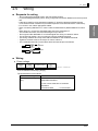
2.5
Wiring
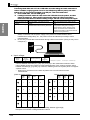
■ Setting example
:
Master --- PMU2A (power two-system)
Slave --- EMU8A (pulse/temperature)
CTD8E (CT expansion)
Purpose
:
Classification of operating signals (condition) for the facilities
of 3-phase 3-wire line.
Extraction of waste in the electric power of single-phase
2-wire
Measurement of electric power in facilities of each line.
Setting switch
:
Set the Pin no. 2 of DIP switch to OFF (CompoWay/F) across
the entire system.
Using the rotary switch, set the slave ID.
EMU8A (pulse/temperature) --- 5 (to use event input for
3-STATE)
CTD8E (CT expansion)
--- 1 (Because the setting range
of slave ID is from 1 to 4)
Unit no.
:
PMU2A
--- 01 (Because the setting range of unit no. is from
00 to 99.)
EMU8A
--- 02 (Because the setting range of unit no. is from
00 to 99)
CTD8E
--- 03 (Because the setting range of unit no. is from
00 to 99.)
* A unit no. is assigned by higher equipment (example: PC) to identify units from each other.
0
-
Connection configuration
0
0
-
:
With/without
slave ID 6
H’11
1
0
0
0
1
With/without
slave ID 5
With/without
slave ID 4
With/without
slave ID 3
With/without
slave ID 2
With/without
slave ID 1
1
1
Power
電 R
源
supply
側 S
side (K)
(K)
負
Load
荷
側 (L)
side
(L)
T
Load
負荷
Load
負荷
Load
負荷
PMU2A
EMU8A
CTD8E
(Power
( 電力
2 系統 )
(Pulse/
( パルス
/ 温度 )
(CT(CT
expansion)
増設 )
two-system)
temperature)
:CT
スレSlave
ーブ IDID:
:55
02
No.02
ユニUnit
ット no.
Unit no. 01
ユニット No.01
Load
負荷
Power
電
supply
源 L
側 N
side (K)
(K)
Load
負荷
Load
負荷
SlaveID
ID:
スレーブ
:15
03
No.03
ユニUnit
ットno.
Load
負荷
Load
負荷
Load
負荷
Load
負
荷
side
側(L)
(L)
2-3
Preparation
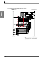
System Configuration
0BPreparation
● Setting list of units
Preparation
PMU2A (power two-system)
Electrical system 1 applicable phase wire
: 3-phase 3-wire
Electrical system 2 applicable phase wire
: Single phase 2-wire
Dedicated CT type for measuring block 1
: 50 A
Dedicated CT type for measuring block 2
: 5A
Measurement start time
: 08:30
Measurement end time
: 17:15
Measuring block 1 3-STATE judgment target
: Event input
Measuring block 2 3-STATE judgment target
: Electric power
Measuring block 1 3-STATE/p3-STATE/original unit event input
Measuring block 2 3-STATE HIGH threshold
: 100.0
Measuring block 2 3-STATE LOW threshold
: 80.0
Measuring block 2 3-STATE hysteresis
: 5.0
Connection configuration
: H’11
Unit no.
: 01
Communication speed
: 9.6 kbps
Data bit length
: 7 bits
Stop bit length
: 2 bits
Vertical parity
: Even
Transmission wait time
: 20 ms
Electrical system 1
applicable
phase wire
系統1適用相線式
Electrical system 2
applicable phase wire
系統2適用相線式
11
12
23
24
9
10
21
22
KM1-PMU2A-FLK
Measurement block 2
計測ブロッ
ク2 2)
(CT input of system
(系統2のCT入力)
RS-485
Output
出力
Power voltage
電源電圧
2-4
7
8
19
20
5
6
17
18
3
4
15
16
1
2
13
14
Measurement block 1
計測ブロッ
ク1
(CT input of
system 1)
(系統1のCT入力)
: 1 and 2
2.5
3-ST (3-STATE classification)
3-ST (3-STATE classification)
PNP (With voltage)
PNP (With voltage)
N-O (Normally open)
N-O (Normally open)
02
9.6 kbps
7 bits
2 bits
Even
20 ms
Thermistor
output
サーミスタ入力
Event
input
2
ベント入
力2
イ
Event
input
1
イ
ベント入
力1
:
:
:
:
:
:
:
:
:
:
:
:
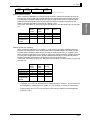
Preparation
EMU8A (pulse/temperature)
Event input setting 1
Event input setting 2
Event input 1 NPN/PNP input mode setting
Event input 2 NPN/PNP input mode setting
Event input 1 input mode setting
Event input 2 input mode setting
Unit no.
Communication speed
Data bit length
Stop bit length
Vertical parity
Transmission wait time
Wiring
11
12
23
24
9
10
21
22
KM1-EMU8A-FLK
Event
input力7
7
イベント入
Event
input力6
6
イベント入
RS-485
Output
出力
Power
voltage
電源電圧
7
8
19
20
5
6
17
18
3
4
15
16
1
2
13
14
CTD8E (CT expansion)
Electrical system 1 applicable phase wire
measurement master setting)
Electrical system 2 applicable phase wire
the measurement master setting)
Measuring block 1 sync select
Measuring block 2 sync select
Dedicated CT type for measuring block 1
Dedicated CT type for measuring block 2
Unit no.
Event
input力5
5
イベント入
Event input力4
4
イベント入
Event
input力3
3
イベント入
: 3 phase 3-wire (to conform to the
: Single phase 2-wire (to conform to
:
:
:
:
:
Electrical system 1
Electrical system 2
50 A
5A
03
Measurement
block 2
計測ブロック2
11
12
9
10
23
24
21
22
KE1-CTD8E
Output
出力
3
4
19
20
17
18
15
16
13
14
Measurement
計測ブロッ
ク1 block
1
* For the setting range for each item, refer to "List of parameters" on Page A-9.
2-5
0BPreparation
2.2
Installation
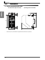
■ External dimensions (unit: mm)
45 in width X 96 in height X 90 in depth
Preparation
45
*
2-6
(6)
90
Dimensions put in parentheses are applicable when DIN hook is pulled out.
96
35
101
(6)
20
(Protruding portion is not included)
2.5
Wiring
■ Connection method
Using horizontally connecting hooks and connection connectors, connect adjacent units to each
other.
● Horizontally connecting hook
This hook is used to securely fix units to each other on the DIN rail.
Preparation
x Installation procedure
Slide the white, horizontally connecting hooks on top and at the bottom of the
product until a clicking sound is heard and lock.
"Clicking"
x Removal procedure
Pushing the protruding portion encircled, slide it in the direction opposite to that in
which locking is done for installation.
2-7
0BPreparation
● Connector
This connector is used to connect units to each other.
Inter-unit communication can be carried out to expand functions.
x Installation procedure
Lift the cover on top of the product and set the connection connector. Close the
cover before use.
Preparation
x Removal procedure
Open the lid at the top of the product, and remove the connection connector by
hooking a flat head screwdriver on the red circle portion shown in the figure.
*
*
Be careful not to make the flat head screwdriver contact the internal board.
1 When multiple units are used within the system, be sure to install the connector by
locking it with the horizontal connecting hook.
2-8
2.5
Wiring
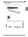
■ Installation procedure
● Installation of DIN rail
When installing Model KM1, use the DIN rail or screws.
When using the DIN rail, fix it with three or more screws within the control panel.
x
Model PFP-100N
Model PFP-50N
1,000 mm
500 mm
x
End plate Model PFP-M (2 pieces)
x
Installation direction
Manufacturer
Preparation
Recommended DIN rail
Model
Dimensions
OMRON
The installation direction of Model KM1 has been determined. As shown below, place the
DIN rail vertical to the ground and install it in the horizontal direction.
Vertical: {
Horizontal: ×
Lateral: O
Longitudinal: X
2-9
0BPreparation
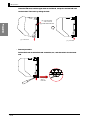
x
Installation procedure
Lower the DIN hook, hook the upper claw on the DIN rail, and push it until the DIN hook
can be locked. Then lock it by raising the hook.
[2] Hook the upper
②上部の爪を
claw on the rail
レールにかける
Preparation
[3] Insert③本体を押し込む
the main unit.
[1] Lower
hook げる
①フックを下
x
[4] Lock
this.
④ロックする
Removal procedure
Pull the DIN hook out with a flat head screwdriver, etc., and then raise it from the lower
side.
Enlarged
view of
front side
2-10
2.5
Wiring
● Installation on a wall
If the product is used as a single unit, it can be installed on a wall. When using multiple units, be
sure to install them in the DIN rail.
x
Installation procedure
45
102
Preparation
x
Installation procedure
Pull two DIN hooks on the back of the product to the outside until a clicking sound is
heard. Put them in the DIN hook holes and install them with M4 screws.
M4 screw
2-11
0BPreparation
2.3
Installation of dedicated CT
Preparation
The dedicated CT is divided into the two types: split type and panel fixed (through) type.
[Common]
x Measurement with single-phase 2-wire requires one dedicated CT, measurement with
single-phase 3-wire or 3-phase 3-wire requires two dedicated CTs, and measurement with
3-phase 4-wire requires three dedicated CTs.
x Use of dedicated CTs in a circuit requires all the CTs to have the same standard.
x The standard of the dedicated CTs to be used should match the settings of the dedicated
CT of Model KM1.
x A dedicated CT has its polarity. Carry out wiring correctly between (K) and (L).
For terminal positions, refer to Page 2-14 and later.
x Before making connections, confirm the directions of power supply side (K) and load side
(L). Wrong direction prevents correct measurements.
x Securely close the terminal cover on the secondary side of dedicated CT.
x Do not ground the dedicated CT. Doing so causes a failure.
x Electric shocks may occur.
For the primary side wire to be clamped in CT, be sure to use a covered electric wire of 600
V or more in basic insulation.
When using a conductive object, such as bus bar, for clamping, ensure the basic insulation
at least by, e.g., covering with an insulator.
x Avoid direct clamping in a line of 600 VAC or more.
[Split type]
x Open the hook for the split/fixed type and clamp each phase. After clamping, securely
perform fitting until a clicking sound is heard.
[Panel fixing (through) type]
x Securely fix the dedicated CT to the panel, etc.
Load負荷側
side
(L) (L)
Load負荷側
side
(L) (L)
Hook
分割/for
split/fixing
type
固定用フック
KM
20
-CT
・F・・
LOT
・・・
No.・
・・・
・・
L
K
電源側
Loading
(K)
side (K)
For fixing a banding
結束バンド等
band,
etc.
の固定用
Terminal
CT二次側 cover on the secondary
端子カバー
side
of dedicated CT
Split type
2-12
Loading
電源側
side
(K)
(K)
Panel fixing (through) type
2.5
Wiring
■ Wire connection and installation of dedicated CT
This section describes the wire connection for each phase wire and the installation of dedicated
CT.
Single-phase 2-wire
Single-phase 3-wire
単相 3 線式
単相 2 線式
CT
負
荷
Load
Load
負
荷
Preparation
~
Product
製品
To
input
CTCT入力へ
~
N
負
荷
Load
CT
Product
製品
ToCT
CT入力へ
input
R
Load
負
荷
CT
Product
製品
To
input
CTCT入力へ
3-phase
(U(△(
(delta)
wire connection)
三相 3-wire
3 線式
デルタ
) 結線 )
3-phase
3-wire
(V wire
connection)
3 線式
三相
(V結線
)
R
R
CT
CT
~
S
製品
Product
~ ToCT
CT入力へ
input
Lo
負
荷
ad
ad
負
荷
T
負
Lo
荷
Load
T
~
負
Lo
荷
ad
S
Lo
負
ad荷
負
荷
Product
製品
~ To CT
CT入力へ
input
~
S
Load
CT
CT
製品
Product
To CT
CT 入力へ
input
製品
Product
To CT
CT入力へ
input
3-phase 4 wire (Y (star) wire connection)
三相 4 線式 (Y( スター ) 結線 )
Load
負
荷
T
n
負
荷
負
荷
CT
Product
~
製品
ToCT
CT入力へ
input
N
~
~
S
Load
R
Load
CT
Product
製品
ToCT
CT入力へ
input
CT
Product
製品
ToCT
CT入力へ
input
*
When installing the dedicated CT, set K and L at the power supply side and load side, respectively.
2-13
0BPreparation
2.4
Input/output configuration and example
of wiring diagram
Terminal arrangements should be confirmed according to the numbers printed on the side face of
the product and on the terminal block.
■ Model KM1-PMU1A-FLK
Preparation
● Terminal arrangements and input/output configuration
11
12
9
10
P3
P0
23
24
P1
P2
21
22
Input
voltage11
電圧入力
KM1-PMU1A-FLK
RS-485
RS-485 通信
communication
7
A(-)
OUT
1 to
OUT1
~33
Total
power consumption
積
算電力量パルス出力
pulse output
警報出力
Alarm output
19
8
RS-485
20
B(+)
5
6
17
3
4
15
CT3
S L
18
入力
CTCT
inputs
1 to 3
16
1~3
CT2
S L
1
Power
voltage
電源電圧
2
13
PWR
CT1
S L
14
● Function of terminal
1
2
Power
voltage
電源電圧
(AC100 ~ 240V)
9
NC
17
CT‐3S
10
NC
18
CT‐3L
3
Transistor
output
COM
トランジスタ
出力 COM
11
NC
19
NC
4
トランジスタ
出力1 1
Transistor
output
12
NC
20
NC
5
トランジスタ
出力2 2
Transistor
output
13
CT‐1S
21
Measurement
voltage P1
input P1
計測電圧入力
6
トランジスタ
出力3 3
Transistor
output
14
CT‐1L
22
Measurement
voltage P2
input P2
計測電圧入力
7
RS‐485 A(-)
15
CT‐2S
23
Measurement
voltageP3
input 3
計測電圧入力
8
RS‐485 B(+)
16
CT‐2L
24
Measurement
voltageP0
input 0
計測電圧入力
2-14
2.5
Wiring
● Example of wiring diagram
Single-2
wire
・単相
2 線式
Single-3
wire
・単相
3 線式
Power
supply side (K)
電源側 (K)
Power supply
電源側 side
(K) (K)
Load (L
side
負荷側
) (L)
L
N
P1
RNT
P2
11
12
23
24
11
12
23
24
9
10
21
22
9
10
21
22
RS-485 communication
RS‐485 通信
7
8
19
20
Transistor
output
トランジスタ出力
(OUT1to~OUT3)
OUT3)
(OUT1
5
6
17
18
3
4
15
16
1
2
13
14
Transistor
output COM
トランジスタ出力
COM
KM1-PMU1A-FLK
RS-485
RS‐485 communication
通信
CT3 input
CT3 入力
Transistor
output
トランジスタ出力
(OUT1
OUT3)
(OUT1
to ~
OUT3)
CT2
CT2 input
入力
Transistor output COM
トランジスタ出力 COM
CT1 input
CT1 入力
Load
side
負荷側
(L) (L)
Power
voltage
電源電圧
12
23
7
8
19
20
5
6
17
18
3
4
15
16
1
2
13
14
10
21
3-phase
4-wire
4 線式
・三相
Power 電源側
supply(K)
side (K)
Power 電源側
supply(K)
side (K)
RST
RSTN
24
22
11
12
P2
P1
9
10
KM1-PMU1A-FLK
RS-485
RS‐485communication
通信
7
8
19
20
Transistor
output
トランジスタ出力
(OUT1
(OUT1to~OUT3)
OUT3)
5
6
17
18
3
4
15
16
1
2
Transistor
output COM
COM
トランジスタ出力
13
Power
voltage
電源電圧
CT1入力
input
CT1
Load
side (L)
負荷側 (L)
23
24
P0
P3
21
22
P2
P1
P3
9
CT3 input
CT3 入力
Power
voltage
電源電圧
3-phase
3-wire
3 線式
・三相
11
P2
P1
Preparation
KM1-PMU1A-FLK
P3
KM1-PMU1A-FLK
CT3 input
CT3 入力
RS-485
RS‐485communication
通信
7
8
19
20
Transistor
output
トランジスタ出力
(OUT1
(OUT1to~OUT3)
OUT3)
5
6
17
18
3
4
15
16
1
2
13
14
Transistor
output COM
COM
トランジスタ出力
CT1入力
input
CT1
14
Load
負荷側side
(L) (L)
Power
voltage
電源電圧
CT3 input
CT3 入力
CT2
input
CT2
入力
CT1 input
CT1 入力
Load
side
負荷側
(L) (L)
2-15
0BPreparation
■ Model KM1-PMU2A-FLK
● Terminal arrangements and input/output configuration
2-P3
Preparation
Voltage
input 2
2
電圧入力
1-P3
11
12
23
24
2-P1
2-P2
1-P1
1-P2
9
10
21
22
Voltage
input 1
電圧入力
1
KM1-PMU2A-FLK
RS-485
RS-485 通信
communication
7
A(-)
OUT 1 ~
to 33
OUT1
Total power consumption
積算電力量パルス出力
pulse output
警報出力
Alarm
output
8
RS-485
19
B(+)
5
6
17
3
4
15
CT4
S L
CT3
S L
20
18
16
CT2
S L
1
Power
voltage
電源電圧
2
13
PWR
CT1
S L
14
CT input of
電圧入力
2の
voltage input 2
CT 入力
CT input of
1の
圧入力
電voltage
input 1
CT 入力
● Function of terminal
1
2
Power
voltage
電源電圧
(AC100 ~ 240V)
9
Measurement
voltage 2‐P1
input 2-P1
計測電圧入力
17
CT‐3S
10
Measurement
voltage 2‐P2
input 2-P2
計測電圧入力
18
CT‐3L
3
トランジスタ
出力 COM
Transistor
output
COM
11
Measurement voltage input 2-P3
計測電圧入力 2‐P3
19
CT‐4S
4
トランジスタ出力1
Transistor
output 1
12
DO NOT USE
20
CT‐4L
5
Transistor
output 2
トランジスタ出力2
13
CT‐1S
21
Measurement
voltage
input P1
計測電圧入力
1‐P1
6
Transistor
output 3
トランジスタ出力3
14
CT‐1L
22
Measurement
voltage
input P2
1‐P2
計測電圧入力
7
RS‐485 A(-)
15
CT‐2S
23
8
RS‐485 B(+)
16
CT‐2L
24
2-16
Measurement voltage input P3
計測電圧入力 1‐P3
DO NOT USE
2.5
Wiring
● Example of wiring diagram
System 1
系統1
Power supply
side
電源側
(K)(K)
LN
L N
Preparation
Single-phase
2-wire
2 線式
・単相
System 2
系統2
Power
supply
電源側
(K) side (K)
L N LN
2-P1
2-P2
11
12
23
24
9
10
21
22
1-P1
1-P2
KM1-PMU2A-FLK
CT4 input
CT4入力
RS-485
communication
RS‐485
通信
7
8
19
20
負荷
Load
CT3 input
CT3入力
Transistor
output
トランジスタ出力
(OUT1 to~
OUT3)
(OUT1
OUT3)
Transistor outputCO
COM
M
トランジスタ出力
5
6
17
18
3
4
15
16
1
2
13
14
CT2 input
CT2入力
Load
負荷
負荷
Load
CT1 input Load
CT1入力 負荷
Power
voltage
電源電圧
Load
負荷side
側 (L(L)
)
Single-phase
3-wire
3 線式
・単相
System
1
系統1
Power supply
side
電源側
(K)(K)
RNT
R NT
Load (side
負荷側
L) (L)
System
系
統2 2
Power
電源supply
側 (K) side (K)
R NRNT
T
2-P1
2-P3
2-P2
11
12
9
10
23
24
21
22
1-P3
1-P1
1-P2
KM1-PMU2A-FLK
CT4 input
CT4入力
RS-485 communication
RS‐485 通信
Transistor output
トランジスタ出力
(OUT1 to OUT3)
(OUT1 ~ OUT3)
Transistor output COM
トランジスタ出力 COM
7
8
19
20
CT3 input
CT3入力
5
6
17
18
CT2 input
CT2入力
3
4
15
16
1
2
13
14
CT1 input
CT1入力
Power
voltage
電源電圧
Load
side
負荷
側 (L)
(L )
Load side
負荷側
(L) (L)
2-17
0BPreparation
Preparation
3-phase 3-wire
3 線式
・三相
・三相
System
系統1 1
Power電源側
supply(K)
side (K)
RRST
ST
System 2
系統2
Power
side (K)
電源側supply
(K)
R S T RST
2-P1
2-P3
2-P2
11
12
9
10
23
24
21
22
1-P3
1-P1
1-P2
KM1-PMU2A-FLK
CT4 input
CT4入力
RS-485 communication
RS‐485 通信
8
19
20
5
6
17
18
3
4
15
16
7
CT3 input
CT3入力
Transistor
output
トランジスタ出力
(OUT1
to ~
OUT3)
(OUT1
OUT3)
Transistor output COM
トランジスタ出力 COM
CT2 input
CT2入力
CT1 input
CT1入力
1
2
13
Power
voltage
電源電圧
2-18
14
Load side
負荷側
(L) (L)
Load
負荷側
(L) side (L)
2.5
Wiring
■ Model KM1-EMU8A-FLK
● Terminal arrangements and input/output configuration
12
23
24
Event
input 1,1、
2 2
イベ
ント入力
9
10
21
22
Thermistor input
サーミスタ入力
イベント入力
Event input 7
7
*
*
Preparation
11
*
KM1-EMU8A-FLK
7
RS-485 communication
RS-485 通信
A(-)
8
RS-485
6
5
OUT1 to 3
OUT1 ~ 3
Alarm
output
警報出力
B(+)
19
20
*
17
18
*
3
4
15
Event input 3 to 6
イベント入力
3~6
16
*
1
Power
voltage
電源電圧
2
PWR
13
14
*
*有電圧・無電圧の設定が可能です。
* With Voltage/Without
Voltage can be set.
● Function of terminal
1
2
Power
voltage
電源電圧
(AC100 ~ 240V)
9
Event input 11(+)
(+)
イベント入力
17
Event
input 55(+)
(+)
イベント入力
10
Event input 11(-)
(-)
イベント入力
18
Event
input 55(-)
(-)
イベント入力
3
Transistor
output
COM
トランジスタ
出力 COM
11
イベント入力
Event input 22(+)
(+)
19
イベント入力
Event
input 66(+)
(+)
4
出力1 1
トランジスタ
Transistor
output
12
イベント入力
Event input 22(-)
(-)
20
イベント入力
Event
input 66(-)
(-)
5
Transistor
output
出力2 2
トランジスタ
13
イベント入力
Event input 33(+)
(+)
21
イベント入力
Event
input 77(+)
(+)
6
Transistor
output
トランジスタ
出力3 3
14
イベント入力
Event input 33(-)
(-)
22
イベント入力
Event
input 77(-)
(-)
7
RS‐485 A(-)
15
イベント入力
Event input 44(+)
(+)
23
Thermistor
input
サーミスタ入力
8
RS‐485 B(+)
16
イベント入力
Event input 44(-)
(-)
24
Thermistor
input
サーミスタ入力
2-19
0BPreparation
■ Model KE1-CTD8E
● Terminal arrangements and input/output configuration
Preparation
Measurement
11
9
CT8
S L
CT7
S L
12
23
10
21
CT6
S L
CT5
S L
24
2
計測ブロック
block 2
22
5 ~ 8
CT
CTinputs
入力5 to 8
KE1-CTD8E
7
OUT 1 OUT1
Alarm警報出
output 力
8
19
5
6
17
3
4
15
1
2
13
CT4
S L
CT3
S L
CT2
S L
CT1
S L
20
Measurement
block 1
1
計測ブロック
18
CT inputs 1 to 4
CT 入力
1~4
16
14
* Use of the setting tool can assign Measuring block 1 and measuring block 2 to electrical system 1
and electrical system 2 of the master arbitrarily.
● Function of terminal
1
NC
9
CT‐7S
17
CT‐3S
2
NC
10
CT‐7L
18
CT‐3L
11
CT‐8S
19
CT‐4S
12
CT‐8L
20
CT‐4L
3
4
1arelay
リレー出力
1a
output
5
NC
13
CT‐1S
21
CT‐5S
6
NC
14
CT‐1L
22
CT‐5L
7
NC
15
CT‐2S
23
CT‐6S
8
NC
16
CT‐2L
24
CT‐6L
2-20
2.5
Wiring
● Example of wiring diagram
Single-phase
・単相
2 線式 2-wire
Power電源側
supply
(K)side (K)
L N
例:8
回路の電力計測の場合
Example:
For power measurement on 8 circuits
Preparation
P1
CT8
CT8input
入力
P2
負荷
CT7 入力 Load
CT7 input
11
12
23
24
11
12
23
24
9
10
21
22
9
10
21
22
KM1-PMU□A-FLK
CT6
CT6input
入力
負荷
Load
CT5
CT5input
入力
負荷
Load
負荷
Load
KE1-CTD8E
CT4 input
CT4 入力
1a relay
output
1a リレー出力
7
8
19
20
7
8
19
20
5
6
17
18
5
6
17
18
3
4
15
16
3
4
15
16
1
2
13
14
1
2
13
14
Load
CT3 入力 負荷
CT3 input
**形Model
KE1-CTD8E
does not operate as a single
KE1-CTD8E
は単体では動作しません。
unit.
必ず計測マスタと連結してご使用ください。
For the operation, be sure to connect it to the
線種により必要な
CT 入力数が異なります。
*各measurement
master.
Load
負荷
線式:CT1
入力 required differ depending on
* 単相
The2number
CT inputs
line KE1-C
type. TD8E で計測できる回路数は
*1 the
台の形
負荷
Load
Single-phase 2-wire: CT1 input
以下の通りです。
* The number of circuits that can be measured in one
負荷側
Load
side(L)(L) 単相 2 線式:最大 8 回路
Model KE1-CTD8E unit is as follows:
Single-phase 2-wire: Up to 8 circuits
Load
CT2 入力 負荷
CT2 input
CT1 input
CT1 入力
Power
voltage
電源電圧
Single-phase
・単
相 3 線式 3-wire
Power 電源側
supply(K)
side (K)
例:4
回路の電力計
測の場合
Example:
For power
measurement on 4 circuits
RNT
CT8 input
CT7 入力
P1
P3
CT7 input
CT8 入力
P2
負荷
Load
11
12
23
24
11
12
23
24
CT6 input
9
10
21
22
9
10
21
22
CT5 input
KE1-□□□1□-FLK
CT6 入力
CT5 入力
KE1-CTD8E
Load
負荷
負荷
Load
1a relay
1a リレー出力
output
7
8
19
20
7
8
19
20
5
6
17
18
5
6
17
18
3
4
15
16
3
4
15
16
1
2
13
14
1
2
13
14
CT4 input
CT4 入力
CT3 input
CT3 入力
負荷
Load
CT2
CT2input
入力
CT1
CT1input
入力
電源電圧
Power
voltage
Load負荷
side
側 (L)
(L)
* Model KE1-CTD8E does not operate as a single
*形 KE1-CTD8E は単体では動作しません。
unit.
必ず計測マスタと連結してご使用ください。
For the operation, be sure to connect it to the
CT 入力数が異なります。
*各線種により必要な
measurement master.
線式:CT2
* 単相
The3number
CT 入力
inputs required differ depending on
line KE1-CTD8E
type.
*1 the
で計測できる回路数は
台の形
Single-phase 3-wire: CT2 input
以下の通りです。
* 単相
The3number
of circuits
線式:最大
4 回路 that can be measured in one
Model KE1-CTD8E unit is as follows:
Single-phase 3-wire: Up to 4 circuits
2-21
0BPreparation
3-wrie
・3-phase
・三相
三相 3 線式
例:4
回路の電力計測の場合
Example:
For power measurement on 4 circuits
Power
supply
電源側
(K) side (K)
RST
Preparation
CT7 input
入力
P1
P3
P2
CT8 input
入力
負荷
Load
11
12
23
24
11
12
23
24
9
10
21
22
9
10
21
22
KE1-□□□1□-FLK
CT6入力
input
CT6
CT5
CT5入力
input
KE1-CTD8E
負荷
Load
* Model
KE1-CTD8E
does not operate as a single
*形
KE1-CTD8E
は単体では動作しません。
unit. マスタと連結してご使用ください。
必ず計測
For the operation, be sure to connect it to the
*各線種により必要な
CT 入力数が異なります。
measurement master.
三相
3 線式:CT2
* The
number CT入力
inputs required differ depending on
the lineKE1-CTD8E
type.
*1 台の形
で対応できる回路数は
3-phase 3-wire: CT2 input
以下の通りです。
* The
number
of circuits
三相
:最大
3 線式
4 回路 that can be measured in one
Model KE1-CTD8E unit is as follows:
3-phase 3-wire: Up to 4 circuits
負荷
Load
1a リレー出力
1a relay
output
7
8
19
20
7
8
19
20
5
6
17
18
5
6
17
18
3
4
15
16
3
4
15
16
1
2
13
14
1
2
13
14
CT4 input
CT4 入力
CT3入力
input
CT3
負荷
Load
CT2入力
input
CT2
CT1
CT1入力
input
電源電圧
Power
voltage
負荷側
Load side
(L)(L)
・3-phase
・三相
三相 4 4-wire
線式
例:2
回路の電力計測の場合
Example:
For power measurement on 2 circuits
Power
supply side (K)
電源側 (K)
RSTN
P1
P3
P2
P0
CT7 input
CT7 入力
CT6入力
input
CT6
11
12
23
24
11
12
23
24
9
10
21
22
9
10
21
22
CT5 input
CT5 入力
KM1-PMU1A-FLK
1a リレー出力
1a relay
output
KE1-CTD8E
7
8
19
20
7
8
19
20
5
6
17
18
5
6
17
18
3
4
15
16
3
4
15
16
1
2
13
14
1
2
13
14
電源電圧
Power
voltage
Load
負荷
CT3 input
CT3 入力
CT2入力
input
CT2
CT1 input
CT1 入力
Load
負荷
* Model KE1-CTD8E does not operate as a single
*形 KE1-CTD8E は単体では動作しません。
unit.
必ず計測マスタと連結してご使用ください。
For the operation, be sure to connect it to the
*三相
KM1-PMU1A-FLK
4 線式を計測する場合は形
measurement
master.
と連結してご使用ください。
* When measuring 3-phase 4-wire, connect to Model
*各線種により必要な
KM1-PMU1A-FLK.CT 入力数が異なります。
* The
number
CT入力
inputs required differ depending on
三相
4 線式:
CT3
the lineKE1-CTD8E
type.
*1 台の形
で対応できる回路数は
3-phase 4-wire: CT3 input
以下の通りです。
* The number of circuits that can be measured in one
三相 4 線式:最大 2 回路
Model KE1-CTD8E unit is as follows:
3-phase 4-wire: Up to 2 circuits
Load
side(L)(L)
負荷側
2-22
2.5
Wiring
3 線式
2 回路
・三相
/ 単相 2 線式 4 回路
3-phase
3-wire
2-circuit/single-phase
2-wire 4-circuit
Power
supply
電源側
(K) side (K)
Power
side (K)
電源側supply
(K)
RST
L N
Preparation
CT7
CT7input
入力
P1
P3
P2
CT8 input
CT8 入力
Load
負荷
CT6
CT6input
入力
11
12
9
10
23
24
11
12
23
24
21
22
9
10
21
22
KM1-PMU2A-FLK
1a リレー出力
1a relay
output
7
8
19
20
7
8
19
20
5
6
17
18
5
6
17
18
3
4
15
16
3
4
15
16
1
2
13
14
1
2
13
14
Power
voltage
電源電圧
負荷
Load
Load
負荷
Load
負荷
KE1-CTD8E
CT5 入力
input
CT5
負荷
Load
CT4
CT4input
入力
CT3 input
CT3 入力
CT2
CT2input
入力
CT1 input
CT1 入力
負荷
Load
Load(L)
side (L)
負荷側
Load負荷側
side (L)
(L)
* *Model
KE1-CTD8E
does not operate as a single
形 KE1-CTD8E
は単体では動作しません。
unit.
2 系統を計測する場合は形 KM1-PMU2A-FLK
To measure two systems, connect it to Model
KM1-PMU2A-FLK.
と連結してご使用ください。
2-23
0BPreparation
Single-phase
4-circuit/single-phase
2-circuit
・単相
・
単相
2 線式2-wire
4 回路
/ 単相 3 線式3-wire
2 回路
Power supply
電源側side
(K) (K)
電源側
(K) side (K)
Power
supply
RNT
L N
Preparation
CT7
CT7input
入力
P1
P3
CT8
CT8input
入力
P2
負荷
Load
CT6 input
CT6
入力
11
12
9
10
23
24
11
12
23
24
21
22
9
10
21
22
KM1-PMU2A-FLK
1a リレー出力
1a relay
output
7
8
19
20
7
8
19
20
5
6
17
18
5
6
17
18
3
4
15
16
3
4
15
16
1
2
13
14
1
2
13
14
Power電源電圧
voltage
負荷
Load
KE1-CTD8E
CT5 input
CT5
入力
負荷
Load
CT4
input
CT4
入力
CT3
input
CT3
入力
負荷
Load
CT2 input
負荷
Load
CT1 input
CT2 入力
CT1 入力
負荷
Load
Load side (L)
負荷側 (L)
Load負荷側
side (L)
(L)
* Model KE1-CTD8E does not operate as a single
KE1-CTD8E は単体では動作しません。
*形 unit.
To measure two systems, KM1-PMU2A-FLK
connect it to Model
2 系統を計測する場合は形
KM1-PMU2A-FLK. さい。
と連結してご使用くだ
2-24
2.5
2.5
Wiring
Wiring
■ Requests for wiring
Less
than 7.2 mm
7.2mm以下
Less
than 7.2 mm
7.2mm以下
■ Wiring
● Power voltage
PMU1A
(Electric
power)
○
PMU2A
(Power
two-system)
○
EMU8A
(Pulse/temperature)
○
CTD8E
(CT
expansion)
×
O: With input
X: Without input
Connect between terminals [1] and [2].
The specifications are as follows.
Power voltage
Consumed power
AC100 ~ 240 V (50/60
Measurement master : 10 VA or less for
Hz)
independent behavior.
14 VA or less at the time of maximum
expansion
Functional slave
: 10 VA or lower
2-25
Preparation
x Do not change the terminal screws, but use existing screws.
x To prevent being affected by noise, wiring of signal line should be different from that of power
line.
x Cable to be used for wiring terminals excepting CT should be twist pair AWG25 (whose
cross-sectional area is 0.205 mm2) to AWG12 (whose cross-sectional area is 3.309 mm2).
x For circuits in use, select appropriate cables.
x When connecting dedicated CT, use the cable for dedicated CT (Model KM20-CTF-CB3: 3
m).
When doing so, connect the shrinkable tube side to the dedicated CT.
x For RS-485 connection, the total cable length is up to 500 m.
x Do not ground the dedicated CT or RS-485 signal line. Doing so causes a failure.
x For the terminal section, carry out wiring by using a solderless terminal.
x Use wiring materials and crimp tools that are suitable for the solderless terminal.
x Tighten a terminal screw to the torque of 0.69 to 0.88 Nxm.
x For a solderless terminal, use the M3.5 terminal whose shape is as follows.
0BPreparation
● USB port
Connecting Model KM1 and a PC via a USB cable can make settings and read measurement
values. In addition, supplying power from a PC via USB (driving USB bus power) can make
settings only. For the functions available via a USB port, refer to the table below.
*1. For the USB cable, use mini-USB type B.
*2 If settings have been made via USB, remove the USB cable from the product, and then
supply the power to it. When reading measurement values via USB communication,
remove the USB cable once after the setting change, and then connect the product again.
When one product is used
For all models, only settings can be
made.
For all models, settings and reading of
measurement values can be performed.
Preparation
Without power
voltage
With power voltage
*3
*4
When multiple units are connected
Only the measurement master can be
set.
Connecting the measurement master
can perform settings and reading of
measurement values. Settings of the
slave connected to the measurement
master and reading of the measurement
values can be performed.
Connect the USB cable only when USB communication is required. If the USB cable is
always connected, and the power supply to the product is turned ON/OFF due to
instantaneous voltage drop, etc., the product cannot be started up normally to make
measurements.
Do not carry out RS-485 communication during USB communication. (Doing so may return
a response.)
● Input voltage
PMU1A
(Electric
power)
○
PMU2A
(Power
two-system)
EMU8A
(Pulse/temperature)
CTD8E
(CT
expansion)
×
×
: With input in 2 systems
O: With input
X: Without input
Connect between terminals (21), (22), (23), and (24) in the measurement master. When
using PMU2A (power two-system) to make measurements of two systems, perform wiring
between terminals [9], [10], and [11]. However, PMU2A (power two-system) does not support
3-phase 4-wire.
* When wiring, avoid error in the order of phases. An error will cause incorrect
measurement.
[PMU1A (electric power)]
Single
phase
2-wire
Single
phase
3-wire
PMU2A (power two-system)]
3-phase
3-wire
3-phase
4-wire
P1
Single
phase
2-wire
1-P1
L
R
R
P2
1-P2
N
N
S
P3
1-P3
-
T
T
T
-
-
-
N
L
R
R
N
N
S
-
T
T
2-P2
⑩
S
2-P3
⑪
P0
* Indication of voltage: V[A][B]: Indicates a voltage between [A] and [B].
Example: Vrs indicates a voltage between R and S.
2-26
3-phase
3-wire
2-P1
⑨
R
Single
phase
3-wire
2.5
Wiring
● CT input
PMU1A
(Electric
power)
○
PMU2A
(Power
two-system)
○
EMU8A
(Pulse/temperature)
×
CTD8E
(CT
expansion)
○
O: With input
X: Without input
[PMU2A (power two-system)]
When connecting dedicated CT to system 1, perform wiring as follows: between terminals
[13] and [14] and [15] and [16] in single-phase 2-wire; R phase between terminals [13] and
[14] and phase T between terminals [15] and [16] in single phase 3-wire or 3-phase 3-wire.
When connecting dedicated CT to system 2, perform the wiring as follows: between terminals
[17] and [18] in single-phase 2-wire; phase R between terminals [17] and [18] and phase T
between terminals [19] and [20] in single-phase 3-wire or 3-phase 3-wire.
In this case, terminals [13], [15], [17], and [19] are specified as S, and terminals [14], [16], [18],
and [20], as L.
CT1([13]-[14])
CT2([15]-[16])
CT3([17]-[18])
CT4([19]-[20])
Number of
measurement
circuits
*
Single
phase
2-wire
L
L
L
L
4 circuits
Single
phase
3-wire
R
T
R
T
2 circuits
3-phase
3-wire
R
T
R
T
2 circuits
In PMU2A, CT1 and CT2 are assigned for measurements in system 1, and CT3 and CT4
are assigned for measurements in system 2. If, for example, 4 circuits are measured in
single-phase 2-wire, CT1 to CT4 are used. Cross-wiring is therefore required between
systems 1 and 2.
2-27
Preparation
[PMU1A (electric power)]
When connecting dedicated CT, perform wiring as follows: between terminals [13] and [14],
[15] and [16], and [17] and [18] in single-phase 2-wire; phase R between terminals [13] and
[14] and phase T between terminals [17] and [18] in single-phase 3-wire or 3-phase 3-wire;
phase R between terminals [13] and [14], phase S between terminals [15] and [16], and
phase T between terminals [17] and [18] in 3-phase 4-wire.
In this case, terminals [13], [15], and [17] are specified as S, and terminals [14], [16], and [18],
as L.
Single
Single
3-phase 3-phase
phase
phase
3-wire
4-wire
2-wire
3-wire
CT1([13]-[14])
L
R
R
R
CT2([15]-[16])
L
S
CT3([17]-[18])
L
T
T
T
Number of
3 circuits 1 circuit
1 circuit
1 circuit
measurement
circuits
0BPreparation
[CTD8E (CT expansion)]
When connecting dedicated CT, perform wiring as follows: between terminals [9] and [10], [11]
and [12], [13] and [14], [15] and [16], [17] and [18], [19] and [20], [21] and [22], and [23] and [24]
in single-phase 2-wire; phase R between terminals [9] and [10], [13] and [14], [17] and [18], and
[21] and [22], and phase T between terminals [11] and [12], [15] and [16], [19] and [20], and [23]
and [24] in single-phase 3-wire or 3-phase 3-wire; phase R between terminals [13] and [14] and
[21] and [22], phase S between terminals [15] and [16] and [23] and [24], and phase T between
terminals [17] and [18] and [9] and [10] in 3-phase 4-wire.
In this case, terminals [9], [10], [13], [15], [17], [19], [21], and [23] are specified as S, and
terminals [10], [12], [14], [16], [18], [20], [22] and [24] as L.
Preparation
CT1([13]-[14])
CT2([15]-[16])
CT3([17]-[18])
CT4([19]-[20])
CT5([21]-[22])
CT6([23]-[24])
CT7([9]-[10])
CT8([11]-[12])
Number of
measurement
circuits
*1
*2
*3
Single
phase
2-wire
L
L
L
L
L
L
L
L
8 circuits
Single
phase
3-wire
R
T
R
T
R
T
R
T
4 circuits
3-phase
3-wire
3-phase
4-wire
R
T
R
T
R
T
R
T
4 circuits
R
S
T
R
S
T
2 circuits
Do not touch charging metal part of the dedicated CT terminal. Electric shocks may occur.
Do not ground the dedicated CT. Doing so causes a failure.
When measuring electric power containing higher harmonics, such as inverter primary current,
select a dedicated CT having allowance to standard load. For the current waveform (effective
value of 2 A, and peak value of 8 A) as shown below, a dedicated CT of 50 A must be used. If
5ACT is used, saturation occurs, preventing obtaining correct measurement values.
In general, entering a filter, AC reactor, etc., between the power supply and an inverter greatly
changes the ratio of current and effective value of the inverter primary current. The ratio also
changes depending on the capacitor, diode, etc.
Current peak value of 8 A
Current effective value of 2 A
Example of inverter primary current waveform
● RS-485 communication
PMU1A
(Electric
power)
○
PMU2A
(Power
two-system)
○
EMU8A
(Pulse/temperature)
○
CTD8E
(CT
expansion)
×
O: With terminal
X: Without terminal
When using RS-485 communication functions, connect a communication cable between
terminals [8] and [7].
Model
KM1
形 KM1
8
7
B(+)
A termination resistor must be connected to each end
RS-485 of the transmission path. Each termination resistor
A(-)
should be 120 Ω (1/2 W).
Communication connection diagram
x For the connection configuration, 1 : 1 or 1 : N is applicable. The number of connected units
is as follows: when the protocol is CompoWay/F, 31 units, and when Modbus, up to 99 units.
The total cable length is up to a maximum of 500 m. For the cable, use a twisted pair cable
with shield (AWG24 (cross-sectional area of 0.205 mm2) to AWG14 (cross-sectional area of
2.081 mm2).
*
Do not ground the RS-485 signal line. Doing so causes a failure.
*
Do not carry out RS-485 communication during USB communication. (Doing so may
return a response.)
2-28
2.5
Wiring
● Output
PMU1A
(Electric
power)
○
PMU2A
(Power
two-system)
○
EMU8A
(Pulse/temperature)
CTD8E
(CT
expansion)
○
○
O: With output
3
3
OUT1
3
OUT2
4
OUT3
5
6
[CTD8E (CT expansion)]
One relay output point exists.
3
OUT1
4
* For the output terminal functions, refer to Page 3-9.
● Event input
PMU1A
(Electric
power)
×
PMU2A
(Power
two-system)
×
EMU8A
(Pulse/temperature)
○
CTD8E
(CT
expansion)
×
O: With input, X: Without input
Using event input requires a combination of PMU1A (electric power), PMU2A (power-2 system),
and EMU8A (pulse/temperature).
To use event inputs, make connections between terminal [9] and [10], [11] and [12], [13] and
[14], [15] and [16], [17] and [18], [19] and [20], and [21] and [22] in EMU8A (pulse/temperature).
For the event input, either Without voltage or With voltage is settable.
9
9
Event input 11
イベント入力
Event
input 1 1
イベント入力
10
Input without voltage (NPN)
*
10
Input with voltage (PNP)
For the event input, refer to Page 3-16.
2-29
Preparation
Setting output terminals can perform alarm output, total power consumption pulse output, and
3-STATE output.
The output terminals are as follows.
[PMU1A (electric power), PMU2A (power-2 system), EMU8A (pulse/temperature)]
Three transistor output points exist.
[3] Terminal numbers (COM) are common.
Chapter 3
3.1
3.2
Functions
List of functions ..............................................................................................2
Basic functions ...............................................................................................3
3.3
Applicable phase wire .................................................................................................................3
Synchronization selection for measuring block ..................................................................3
Dedicated CT type........................................................................................................................3
VT ratio.............................................................................................................................................4
CT ratio.............................................................................................................................................4
Low-cut function ............................................................................................................................4
z Low-cut current value ..........................................................................................................4
Average count................................................................................................................................4
Average count................................................................................................................................5
Logging function............................................................................................................................5
CT signal detection ......................................................................................................................5
Measurement function ................................................................................................................6
z Active power ...........................................................................................................................6
z Integrated power amount ...................................................................................................6
z Voltage......................................................................................................................................7
z Power factor............................................................................................................................7
z Reactive power ......................................................................................................................7
z Frequency................................................................................................................................7
z Temperature measurement...............................................................................................7
z Simple measurement...........................................................................................................8
z Total power conversion coefficient .................................................................................8
z Pulse conversion coefficient..............................................................................................8
Output function ...............................................................................................9
■ Ouptut terminal 1/output terminal 2/output terminal 3 function setting.......................9
Integrated power amount pulse output................................................................................10
z Pulse output unit..................................................................................................................10
Reverse phase.............................................................................................................................11
Alarm output .................................................................................................................................12
z Alarm history.........................................................................................................................12
z Time chart of alarm output function ..............................................................................12
z Active input setting .............................................................................................................12
z Active power alarm output ...............................................................................................13
z Over current alarm output ................................................................................................13
z Under current alarm output..............................................................................................13
z Over voltage alarm output................................................................................................14
z Under voltage alarm output .............................................................................................14
z Power factor alarm output................................................................................................14
z Reactive power alarm output ..........................................................................................15
z Temperature alarm output ...............................................................................................15
z Reverse phase alarm output...........................................................................................15
3.4
Event input function.....................................................................................16
■
■
3.5
Event input NPN/PNP input mode setting..........................................................................16
Event input N-O/N-C input mode setting ............................................................................16
Pulse input count ........................................................................................................................17
ON time of pulse input ..............................................................................................................17
Function using event input.......................................................................................................17
z Measurement start time/measurement end time .....................................................17
z Power original unit ..............................................................................................................17
z 3-STATE function................................................................................................................17
3-STATE function ........................................................................................18
3-STATE target............................................................................................................................18
3-STATE HIGH threshold/3-STATE LOW threshold......................................................20
3-STATE hysteresis...................................................................................................................20
3.6
Other functions .............................................................................................21
Time.................................................................................................................................................21
Initialization ...................................................................................................................................21
0BChapter 3
Functions
Error detection function
Functions
unctions
Measurement function
Applicab
le circuit
3.1
List of functions
PMU1A
(Electric power)
PMU2A
(Power
two-system)
EMU8A
(Pulse/temperature)
CTD8E
(CT expansion)
Single-phase 2-wire
Single-phase 3-wire
3-phase 3-wire
3-phase 4-wire
Active power
{
{
{
{
{
×
×
×
×
×
×
{
Integrated active power amount
{
×
Current
Voltage
Power factor
Reactive power
Frequency
Pulse input count
ON time of pulse input
{
{
{
{
{
Integrated regeneration power amount
×
×
{
×
×
×
×
×
×
×
{
{
×
×
×
×
Integrated reactive power amount
{
×
Temperature measurement
×
×
{
×
Active power
{
×
Over/under current
{
×
Over/under voltage
{
×
×
Power factor
{
×
Reactive power
{
×
Temperature
×
×
{
×
Reverse phase
{
×
×
{
{
{
×
×
×
{
{
×
×
×
×
{
Additional
function
3-STATE function *1
Power original unit measurement *2
Conversion value
Pulse conversion value
CT signal detection
Simple measurement
Target for log
Refer to Page A-15.
×
×
×
×
×
O: With function
: Support of two systems (for CTD8E (CT expansion), two systems are supported when
connected to PMU2A (power two-system) is connected.)
×: Without function
*1. When using an event input, connect EMU8A (pulse/temperature).
*2. Only when EMU8A (pulse/temperature) is connected
3-2
3.6
3.2
Other functions
Basic functions
Applicable phase wire
PMU1A
(Electric
power)
{
PMU2A
(Power
two-system)
EMU8A
(Pulse/temperature)
×
CTD8E
(CT
expansion)
: With settings of two-system O: With setting X: Without setting
•
•
Set the phase wire to be measured.
Setting range: Single-phase 2-wire, single-phase 3-wire, 3-phase 3-wire, and 3-phase
4-wire (initial value: 3-phase 3-wire)
*1. For PMU2A (power two-system), 3-phase 4-wire cannot be set.
*2. CTD8E (CT expansion) can perform the two-system measurement only when it is
connected to PMU2A (power two-system).
PMU1A
(Electric
power)
×
•
•
PMU2A
(Power
two-system)
×
EMU8A
(Pulse/temperature)
×
CTD8E
(CT
expansion)
{
Functions
Synchronization selection for measuring block
O: With setting X: Without setting
Set the voltage system synchronized with a measuring block.
Setting range: System 1, system 2 (initial value: system 1)
The measuring blocks are divided into measuring block 1 and measuring block 2, which are
assigned to system 1 and system 2, respectively, to perform power measurements. For
PMU1A and PMU2A, since their measuring blocks and voltage systems are fixed, the setting
of synchronization selection for measuring block is not required.
Dedicated CT type
PMU1A
(Electric
power)
{
PMU2A
(Power
two-system)
EMU8A
(Pulse/temperature)
×
• Set the dedicated CTs to be used.
• The dedicated CTs are as follows.
Split type
CT Model
Standard
Model KM20-CTF-5A
5A
Model
50A
KM20-CTF-50A
Model
100A
KM20-CTF-100A
Model
200A
KM20-CTF-200A
Model
400A
KM20-CTF-400A
Model
600A
KM20-CTF-600A
•
*
*
CTD8E
(CT
expansion)
: With settings of two-system O: With setting X: Without setting
Panel fixed (through) type
CT Model
Model KM20-CTB-5A/50A
Standard
5A/50A
Setting range: 5 A, 50 A, 100 A, 200 A, 400 A, 600 A (initial value: 100 A)
CTD8E (CT expansion) can perform the two-system measurement only when it is
connected to PMU2A (power two-system).
PMU2A (power two-system) can set dedicated a CT type for each system. CTD8E (CT
expansion) can set a type for each measuring block.
3-3
0BChapter 3
Functions
VT ratio
PMU1A
(Electric
power)
{
•
•
•
*
PMU2A
(Power
two-system)
EMU8A
(Pulse/temperature)
×
CTD8E
(CT
expansion)
: With settings of two-system O: With setting X: Without setting
Setting a VT ratio can measure a voltage higher than the standard by using general VT.
Accuracy assurance is not applicable to general VT.
Setting range: 001 to 99.99 (initial value: 1.00)
The settings of CTD8E (CT expansion) should conform to those of the measurement
master. In addition, CTD8E (CT expansion) can perform the two-system measurement
only when it is connected to PMU2A (power two-system).
CT ratio
PMU1A
(Electric
power)
{
•
Functions
unctions
•
•
•
*
*
PMU2A
(Power
two-system)
EMU8A
(Pulse/temperature)
×
CTD8E
(CT
expansion)
: With settings of two-system O: With setting X: Without setting
Setting the CT ratio by using general CT can measure currents higher than the standard of
dedicated CT.
The CT ratio of general CT is set to make measurements by combining existing general
CT.
Accuracy assurance is not applicable to general CT.
Setting range: 1 to 1000 (Initial value: 1)
Set it to 1 when it is not used.
CTD8E (CT expansion) can perform the two-system measurement only when it is
connected to PMU2A (power two-system).
<When 5ACT is connected>
二次側
5ACT
出力の
General
of secondary 5 A output
汎用 CT
5A
専用
CT
Dedicated
CT
( 形 KM20-CTF-5A
or Model KM20-CTB-5A/50A
まModel
たは形KM20-CTB-5A
KM20-CTB-5A/50A)
Model KM1
形 KM1
1000A
Low-cut function
•
This function forcibly sets the current measurement value to 0 when the current value
becomes less than (standard current of CT) X (setting ratio).
• The ratio of an unmeasured load current to the standard current is set.
• As a result, setting the current value to 0 can set the electric power to 0. Setting this
function can cut current and power that are measured due to inductive noise in no-load
condition. Set an optimum value.
*1. The low-cut function works only when all currents of a phase connected to dedicated CT
becomes lower than or equal to the set current low-cut value.
*2. Effective values are used to judge low-cut. This means that, if the peak value is higher
than the low-cut value, and the effective value is lower than the low-cut value, the low-cut
function works.
z Low-cut current value
PMU1A
(Electric
power)
c
PMU2A
(Power
two-system)
EMU8A
(Pulse/temperature)
×
CTD8E
(CT
expansion)
: With settings of two-system c: With setting ×: Without setting
When the low-cut function works, the current and (active/reactive) power are fixed to 0, and
the power factor is fixed to 1.
Setting range: 0.1 to 19.9% (Initial value: 0.6%)
* CTD8E (CT expansion) can perform the two-system measurement only when it is
connected to PMU2A (power two-system).
3-4
3.6
Other functions
Average count
PMU1A
(Electric
power)
{
•
•
•
•
PMU2A
(Power
two-system)
{
EMU8A
(Pulse/temperature)
×
CTD8E
(CT
expansion)
{
O: With setting X: Without setting
Average count is set to reduce dispersion in measurement values.
When the average count is set to OFF, the instantaneous value updated every 100 ms is
the latest value.
The following measurement values are averaged: active power, current, voltage, power
factor, and reactive power.
Average value is calculated by the following formula.
Value determined (Average count - 1) + Value measured this
previously X
time X
average count
•
*
1
Average count
= Value determined this time
Setting range: OFF, 2, 4, 8, 16, 32, 64, 128, 256, 512, and 1024 (Initial value: OFF)
Over/under voltage, over/under current, and reverse phase alarm function are not
affected.
Logging function
PMU2A
(Power
two-system)
{
EMU8A
(Pulse/temperature)
{
CTD8E
(CT
expansion)
×
O: With function
X: Without function
•
Six data logging areas have been prepared. Each area can save 588 pieces of data (up to
6 items can be set.)
• Data logging cycle can be selected from among 5 minutes, 10 minutes, 30 minutes, 1 hour,
2 hours, 6 hours, 12 hours, and 24 hours, and is controlled by specifying 0:00 of the
internal clock in the main unit as the starting point.
Example
: When the logging function is set to 18:12, April 1, 2012 based on
the time of the internal clock in the main unit.
Every 5 min
: Saved at 18:15, April 1, 2012. Every 5 min after that
Every 10 min
: Saved at 18:20, April 1, 2012. Every 10 min after that
Every 30 min
: Saved at 18:30, April 1, 2012. Every 30 min after that
Every hour
: Saved at 19:00, April 1, 2012. Every hour after that
Every 2 hours
: Saved at 20:00, April 1, 2012. Every 2 hours after that
Every 6 hours
: Saved at 0:00, April 2, 2012. Every 6 hours after that
Every 12 hours
: Saved at 0:00, April 2, 2012. Every 12 hours after that
Every 24 hours
: Saved at 0:00, April 2, 2012. Every 24 hours after that
•
•
•
For logging, after measurement data within a logging cycle is saved, data is reset to start
the measurement at the next cycle. For example, setting logging cycle of 5 min and
voltage MAX accumulates voltage MAX values every 5 min.
The number of days for which log data can be saved differs depending on logging cycles.
Every 5 min
: 2 days + 1 hour
Every 10 min
: 4 days + 2 hours
Every 30 min
: 12 days + 6 hours
Every hour
: 24 days + 12 hours
Every 2 hours
: 49 days
Every 6 hours
: 147 days
Every 12 hours
: 294 days
Every 24 hours
: 588 days
For logging items that can be set, refer to Page A-15.
CT signal detection
PMU1A
(Electric
power)
{
•
*
PMU2A
(Power
two-system)
{
EMU8A
(Pulse/temperature)
×
CTD8E
(CT
expansion)
{
O: With function
X: Without function
When the CT is connected, and the current whose measurement value is 2% of the
standard current is supplied continuously for 10 or more seconds, the targeted LED lights.
Even when the low-cut function forcibly sets the current measurement value to 0, CT
signal detection turns LED ON, if the actually flowing current is more than 2% of the
standard current.
3-5
Functions
PMU1A
(Electric
power)
{
0BChapter 3
Functions
Measurement function
z Active power
PMU1A
(Electric
power)
PMU2A
(Power
two-system)
EMU8A
(Pulse/temperature)
CTD8E
(CT
expansion)
{
×
: two-system having measurement function O:
With
measurement function
X: Without measurement function
z Integrated power amount
PMU1A
(Electric
power)
PMU2A
(Power
two-system)
EMU8A
(Pulse/temperature)
CTD8E
(CT
expansion)
{
×
: Two-system having measurement function O: With
measurement function
X: Without measurement function
Measurement range: Excess of the measurement range of 0 to 999999999 Wh returns to 0
Wh, continuing the integration.
Power consumption (active power) and reverse power (regenerated power) are integrated
separated from each other. After the conversion of VT and CT ratios, power is also integrated.
Reactive power is also integrated. Via communication, integrated progression reactive power
amount, integrated delayed reactive power amount and integrated total reactive power
amount can be confirmed in units of varh. Each measurable amount is up to 999999999 varh.
When each amount measured reaches 999999999 varh, it is reset to 0 varh. The reactive
power amount to be integrated is divided into the three types: phase progression reactive
power, phase delayed reactive power, and total reactive power of phase progression and
phase delayed absolute values.
When the 3-STATE function is used for integration, the power measured during operation of
the facilities is specified as HIGH integrated power amount, the power measured while the
facilities are waiting is specified as MIDDLE integrated power amount, and the power
measured during stop of facilities is specified as LOW integrated power amount.
*
CTD8E (CT expansion) can perform the two-system measurement only when it is
connected to PMU2A (power two-system).
Measurement values to be logged include PMU1A (electric power) and PMU2A (power
two-system) only. CTD8E (CT expansion) does not have logging function.
¡ Definitions of phase progression and phase delayed of integrated reactive power amount
Whether the active power is active or regenerated, the integration progression reactive power
amount is integrated in the case of phase progression, and integrated delayed reactive power
amount is integrated in the case of phase delayed. In addition, for the integrated total reactive
power amount, the absolute value of progression reactive power amount and the absolute
value of delayed reactive power amount are integrated. The progression and delayed reactive
power amounts are calculated according to the phase of the voltage based current.
*
Progression
reactive power
進み無効電力
-90゚
-Q
-Q
I
回
生
電
力
θ
-180゚
V
0゚
θ
+180゚
I
+Q
+90゚
Active power
Example 2
例2
Active power:
有効電力:回生
regeneration
無効電力:進み
Reactive power:
progression
Regeneration power
Functions
unctions
Measurement range: -99999999.9 to 99999999.9 W (minimum unit: 0.1 W)
The following active powers are measured: instantaneous value, maximum value, and
minimum value.
The active power means a consumed power. Power that is generating electricity is referred to
as regenerated power.
If the input current is less than low-cut setting value, the active power value is forced to be 0 W.
Measurement values to be logged include PMU1A (electric power) and PMU2A (power two-system)
only.
The measurement value of CTD8E (CT expansion) is excluded. (CTD8E (CT expansion)
does not have logging function.)
* CTD8E (CT expansion) can perform the two-system measurement only when it is
connected to PMU2A (power two-system).
有
効
電
力
Example 1
例1
Active
power: Active
有効電力:有効
Reactive power: Delayed
無効電力:遅れ
+Q
Delayed
reactive power
遅れ無効電力
The
following power amounts are integrated whether point power is active or regenerated.
瞬時電力の有効/回生に関わらず以下を積算
•・積算進み無効電力量:-Qを積算
Integrated progression reactive power amount: Integration of -Q
•・積算遅れ無効電力量:+Qを積算
Integrated delayed reactive power amount: Integration of +Q
•・積算総合無効電力量:+Qと-Qの両方の絶対値を積算
Integrated total reactive power amount: Integration of both absolute values of +Q and • Q
3-6
3.6
z
Current
PMU1A
(Electric
power)
PMU2A
(Power
two-system)
EMU8A
(Pulse/temperature)
CTD8E
(CT
expansion)
{
×
Other functions
: Two-system having measurement function O: With
measurement function
X: Without measurement function
Measurement range: 0.000 to 9999.999 A (minimum unit: 0.001 A)
The following currents are measured: instantaneous value, maximum value, and minimum value.
Measurement values to be logged include PMU1A (electric power) and PMU2A (power two-system)
only. The measurement value of CTD8E (CT expansion) is excluded. (CTD8E (CT expansion) does not
have logging function.)
S-phase current of 3-phase 3-wire is calculated based on R-phase and T-phase currents. N-phase
current of single-phase 3-wire is calculated based on R-phase and T-phase currents.
* CTD8E (CT expansion) can perform the two-system measurement only when it is connected to
PMU2A (power two-system).
z Voltage
PMU1A
(Electric
power)
PMU2A
(Power
two-system)
EMU8A
(Pulse/temperature)
CTD8E
(CT
expansion)
{
×
×
: two-system having measurement function O: With
measurement function
X: Without measurement function
z Power factor
PMU1A
(Electric
power)
PMU2A
(Power
two-system)
EMU8A
(Pulse/temperature)
CTD8E
(CT
expansion)
{
×
: Two-system having measurement function O: With
measurement function
X: Without measurement function
Measurement range: -1.00 to 0.00 to 1.00 (units of 0.01 (3 digits))
The following power factors are measured: instantaneous value, maximum value, and minimum value.
When the low-cut function works, the power factor measurement value is fixed to 1.
Measurement values to be logged include PMU1A (electric power) and PMU2A (power two-system)
only. The measurement value of CTD8E (CT expansion) is excluded. (CTD8E (CT expansion) does not
have logging function.)
* CTD8E (CT expansion) can perform the two-system measurement only when it is connected to
PMU2A (power two-system).
z Reactive power
PMU1A
(Electric
power)
PMU2A
(Power
two-system)
EMU8A
(Pulse/temperature)
CTD8E
(CT
expansion)
{
×
: Two-system having measurement function O: With
measurement function
X: Without measurement function
Measurement range: -99999999.9 to 99999999.9 var (minimum unit: 0.1 var)
The following reactive power amounts are measured: instantaneous value, maximum value, and
minimum value.
If the input current is less than the low-cut setting value, the reactive power value is forced to be 0 var.
Measurement values to be logged include PMU1A (electric power) and PMU2A (power two-system)
only. The measurement value of CTD8E (CT expansion) is excluded. (CTD8E (CT expansion) does not
have logging function.)
* CTD8E (CT expansion) can perform the two-system measurement only when it is connected to
PMU2A (power two-system).
z Frequency
PMU1A
(Electric
power)
PMU2A
(Power
two-system)
EMU8A
(Pulse/temperature)
CTD8E
(CT
expansion)
{
×
×
: Two-system having measurement function O: With
measurement function
X: Without measurement function
Measurement range: 45.0 to 65.0 Hz (minimum unit: 0.1 Hz)
z Temperature measurement
PMU1A
(Electric
power)
×
•
•
•
•
•
•
PMU2A
(Power
two-system)
×
EMU8A
(Pulse/temperature)
{
CTD8E
(CT
expansion)
×
O: With measurement function X: Without measurement function
Measurement range: -50.0 to 100.0°C -58.0 to 212.0°F
Ambient temperature is measurable.
Celsius or Fahrenheit is selectable. (Initial value: Celsius)
Setting an arbitrary value can compensate the temperature.
The measurement value is obtained by adding set temperature compensation.
Setting range of temperature compensation:-50.0 to 50.0 (Initial value: 0.0)
3-7
Functions
Measurement range: 0.0 to 99999.9 V (minimum unit: 0.1 V)
The following voltages are measured: instantaneous value, maximum value, and minimum value.
0BChapter 3
Functions
z Simple measurement
PMU1A
(Electric
power)
PMU2A
(Power
two-system)
EMU8A
(Pulse/temperature)
CTD8E
(CT
expansion)
{
×
With
: Two-system having measurement function O:
measurement function
X: Without measurement function
•
Functions
The simple measurement function roughly grasps the power of installed circuits without
making voltage measurements (wiring).
• This function is set when voltage cannot be entered to the Model KM1 due to conditions of
the field, limitations of wiring, etc.
• Simple measurement calculates the power amount by considering a fixed value of power
factor for the fixed value of voltage and actually calculated current value.
• In the simple measurement, the frequency is fixed to 50 Hz. (No change allowed)
• Accuracy assurance is not applicable because the voltage, power factor, and frequency
are fixed.
• Setting range: OFF/ON (Initial value: OFF)
• During the simple measurement, pay attention to the following points.
*1. An overvoltage error or frequency error has not been detected.
*2. The setting of VT is disabled with the simple measurement set to ON.
*3 Since the phase with current has not been measured actually, it is unavailable for
measurement of regenerated power.
*4. CTD8E (CT expansion) can perform the two-system measurement only when it is
connected to PMU2A (power two-system).
*5. The setting is required in each unit.
¡ Voltage on simple measurement
• Set the voltage value to be used in simple measurement.
• Setting range: 0.1 to 9999.9 V (Initial value: 110.0 V)
¡ Power factor on simple measurement
• Set the power factor to be used in simple measurement.
• Setting range: 0.01 to 1.00 (Initial value: 1.00)
z Total power conversion coefficient
PMU1A
(Electric
power)
{
PMU2A
(Power
two-system)
EMU8A
(Pulse/temperature)
×
CTD8E
(CT
expansion)
: With settings of two-system O: With setting X: Without setting
Set a coefficient to be used to convert integrated power.
It can be converted into CO2emissions or currencies according to the value to be set.
Conversion values can be obtained by the following calculation formula.
Conversion value = Total integrated power amount X
Total power conversion coefficient
Setting range: 0.000 to 9999.999 (Initial value: 1.000)
* CTD8E (CT expansion) can perform the two-system measurement only when it is
connected to PMU2A (power two-system).
* CO2emissions differ depending on power business establishments and fiscal years. When
calculating the emissions, refer to the web sites of power companies, etc., and set the
conversion coefficient of integrated power amount.
When calculating the currencies, refer to the web sites of power companies, etc., about power
charge per kWh and set the conversion coefficient of integrated power amount. When converting
into currencies other than Japanese Yen, set values considering their exchange rates.
z Pulse conversion coefficient
PMU1A
(Electric
power)
×
PMU2A
(Power
two-system)
×
EMU8A
(Pulse/temperature)
{
CTD8E
(CT
expansion)
×
O: With setting X: Without setting
Targets for numerical conversion or conversion coefficients can arbitrarily be set to measure
discharge amounts, such as flow rate of exhaust gas, as conversion values.
» Pulse conversion value
• Pulse conversion values can be obtained by the following calculation formula.
Pulse conversion value = Pulse input count X Pulse conversion coefficient
• Setting range: 0.01 to 9999.99 (Initial value: 1.00)
3-8
3.6
3.3
Other functions
Output function
■Ouptut terminal 1/output terminal 2/output terminal 3 function
setting
PMU1A
(Electric
power)
{
•
PMU2A
(Power
two-system)
{
EMU8A
(Pulse/temperature)
{
CTD8E
(CT
expansion)
{
O: With setting
An arbitrary output can be set at each of output terminal 1, output terminal 2, and output
terminal 3. This setting can perform alarm outputs, pulse outputs, 3-STATE outputs, etc.
<When the pulse output has been set>
Only PMU1A (electric power) and PMU2A (power two-system) can set the integrated
power amount pulse output.
When the integrated power amount reaches a pulse output unit set by the user, the pulse
output is carried out.
For details, refer to Page 3-10.
<When 3-STATE output has been set>
Only PMU1A (electric power) and PMU2A (power two-system) can set 3-STATE output.
Terminals can be set to HIGH, MIDDLE, and LOW.
Setting HIGH threshold and LOW threshold can classify integrated power amounts into
three types: HIGH, MIDDLE, and LOW.
This function helps to grasp power consumption condition and to extract loss power.
For details, please refer to Page 3-18.
3-9
Functions
<When setting an alarm output>
When an alarm output is set, the alarm output can be performed only by setting the alarm for the
output terminal setting with alarm parameter setting/alarm output setting made.
» Alarm parameter setting
This setting is made to judge alarms. Alarms that have been set can be confirmed using the
alarm history, status, and alarm LED.
» Alarm output setting
This setting is made to output alarms. Selecting multiple alarms outputs them when one of them
enters an alarm condition.
For the setting range of alarm parameter setting, alarm output setting, and output terminal setting,
refer to "List of parameters" on Page A-9.
A reverse phase alarm not included in the alarm parameter settings is judged as an alarm by
setting the reverse phase detection to ON.
Alarm parameter setting includes the following items, from which an alarm to be judged can be
selected.
[PMU1A (Electric power), PMU2A (Power two-system)]
• Active power alarm
• Over current alarm
•
Under current alarm
• Over voltage alarm
• Under voltage alarm •
Power factor alarm
• Reactive power alarm
[EMU8A (Pulse/temperature)]
• Temperature alarm
[CTD8E (CT expansion)]
• Active power alarm
• Over current alarm
•
Under current alarm
• Power factor alarm
• Reactive power alarm
This function turns the output ON by judging the following cases as alarm detection (hereinafter
referred to as detection): a measurement value is more than the upper threshold of alarm output
or less than the lower limit threshold. When the measured value becomes more than or less than
the range of hysteresis set in the alarm detection condition, it is judged to be alarm return
(hereinafter referred to as return), and the output is turned OFF.
At the time of detection, on-delay, which retains the output OFF for the specified hours and
minutes can be set.
During the output of an alarm, the operation indicator LED of the specified output terminal lights.
* For the reverse phase, refer to Page 3-11.
* Alarm detection/return is judged by a threshold and hysteresis, and an alarm is then output by
considering on-delay for alarm judgment. For details, please refer to Page 3-13.
* If an active input setting is set to OFF, and the input, which is set to OFF, is targeted for an
alarm, it is not judged as an alarm.
0BChapter 3
Functions
Integrated power amount pulse output
PMU1A
(Electric
power)
○
EMU8A
(Pulse/temperature)
PMU2A
(Power
two-system)
○
×
CTD8E
(CT
expansion)
×
O: With function
X: Without function
Each time the integrated power amount reaches a set pulse output unit, pulse is output from the
terminal set by the output pulse setting.
As the power amount increases, the integrated power amount increases, and pulse output cycles
(intervals) become shorter. As the power amount decreases, the integrated power amount
decreases, and pulse output cycles become longer.
Output pulse cycles can be obtained by the following calculation formula.
Pulse output cycle [s] = 3600 [s]/(Power [W]/Pulse output unit [Wh])
The calculation method of pulse output cycles is described taking an example.
Functions
unctions
Example:
When input power is 200 k[W] and pulse output unit is 10 k[Wh] in 3-phase 3-wire, output pulse
cycle = 3600 [s]/(200 k [W]/10 k[Wh]) = 180 [s] is obtained. If the status with input voltage of 10
k[W] is continued for an hour, passage of an hour (3600 s) gives 10 k[Wh]. If an input of 200 k[W]
sets the pulse output unit to 10 k[Wh], 200 k[W]/10 k[Wh] = 20 pulses are output for an hour, and
the cycle is as follows: 3600 [s]/20 pulses = 180 [s]. For the output pulse, one pulse is output (ON)
every 180 [s].
Power supply
電源
0.5s
Output
pulse
出力パルス
1
180s
2
3
ON
OFF
20
180s
1h
When the cycle is shorter than the pulse width, or when the next output is turned ON
immediately after the output is turned OFF, OFF time of 100 ms is given.
If OFF time is short, count error may occur due to scan time such as PLC. Set an appropriate
pulse output unit.
z Pulse output unit
PMU1A
(Electric
power)
{
PMU2A
(Power
two-system)
{
EMU8A
(Pulse/temperature)
×
CTD8E
(CT
expansion)
×
O: With setting X: Without setting
Available when a pulse output is assigned to the output setting.
Any pulse output unit can be set.
Setting range: 1 Wh, 10 Wh, 100 Wh, 1 kWh, 2 kWh, 5 kWh, 10 kWh, 20 kWh, 50 kWh, 100 kWh
(Initial value: 100 Wh)
When the integrated power amount reaches the pulse output, power of the output unit is
subtracted from the integrated power amount to perform pulse output.
The pulse output width is fixed to 500 ms. For 100 ms after the pulse output, next pulse output
is forcibly turned OFF.
Overlap of pulses forcibly turns OFF the output for 100 ms to inhibit turning ON continuously.
パルス出力タイミング
Pulse output timing
100ms
500ms
100ms
500ms
500ms
100ms
100ms
500ms
500ms
*1. T indicates that the pulse output unit is reached.
*2. The target circuit is selected by setting a pulse output circuit.
Setting range : Circuit 1, Circuit 2, Circuit 3, Circuit 4 (Initial value: Circuit 1)
PMU1A (Electric power)
Circuit 1
Circuit 2
Circuit 3
Single-phase
2-wire
Single-phase
3-wire
3-phase
3-wire
3-phase
4-wire
3-10
CT input 1
CT input 1,
3
CT input 1,
3
CT input 1,
2, 3
CT input 2
CT input 3
Circuit 1
CT input 1
CT input 1,
2
CT input 1,
2
PMU2A (Power two-system)
Circuit 2
Circuit 3
CT input 2
CT input 3
CT input 3,
4
CT input 3,
4
Circuit 4
CT input 4
3.6
Other functions
Reverse phase
PMU1A
(Electric
power)
{
PMU2A
(Power
two-system)
EMU8A
(Pulse/temperature)
×
CTD8E
(CT
expansion)
×
: With two-system
Without function
O: With function
X:
Reverse phase means that the phase order of voltages is not normal.
When the phase order is normal, phases R, S, and T are 0°, 120°, and 240°, respectively,
with reference to phase R. If a measurement of the relationships between differences in
phase indicates that the condition is broken and then the broken condition continues for 0.1s
or more, it is judged as reverse phase.
Reverse phase can be used to confirm problems in facilities or wrong wiring.
* Since the condition where phases are not normal is judged as reverse phase, phase-loss
may be judged as reverse phase.
Phase R
Phase S
Phase S
Phase T
Phase T
Normal phases
Functions
Phase R
Reverse phase
3-11
0BChapter 3
Functions
Alarm output
•
•
•
•
*
Alarm output upper/lower limit threshold, alarm output hysteresis, alarm output on-delay
can be set.
Setting hysteresis can prevent frequently turning ON/OFF an alarm even when a
measurement value varies near the alarm output judgment value.
On-delay is a function that keeps the output OFF for the specified hours and minutes. Set
an optimum value.
Setting the upper limit threshold of each alarm to the maximum value turns the upper limit
alarm function OFF, while setting the lower limit threshold to the minimum value turns the
lower alarm function OFF. The setting should be made to use only either upper limit alarm
or lower limit alarm.
Do not use the alarm output function in cases related to safety, e.g., machine control, etc.,
because the function is assumed to detect errors and call attention by sounding a buzzer
or lighting a lamp.
z Alarm history
Functions
unctions
Histories of alarms generated in the past can be confirmed via communication.
Histories of only 20 alarms generated in the past can be read. If the number of alarms
generated exceeds 20, histories are deleted from the oldest one.
Alarm type, and time of alarm generation: The circuit in which an alarm was generated, and
the time of generation are saved at first.
Alarm release time:
Saved when all circuits to be judged have been
alarm-released.
z Time chart of alarm output function
With on-delay setting, without hysteresis setting
Upper limit threshold
上限閾値
Lower limit threshold
下限閾値
Upper limit alarm judgment
上限警報判定
Lower limit alarm judgment
下限警報判定
On-delay judgment
オンディレー判定
*1
Upper limit alarm output
*1
上限警報出力
Lower limit alarm output
下限警報出力
*1. Turn the alarm output OFF if the state remains OFF continuously in on-delay hour/minute and
alarm judgment.
z Active input setting
PMU1A
(Electric
power)
{
•
•
•
•
•
PMU2A
(Power
two-system)
{
{
CTD8E
(CT
expansion)
{
O: With setting
Sets input that performs alarm judgment.
Since 1 bit corresponds to 1 input, bits 0 to 7 correspond to inputs 1 to 8.
Even if input whose bit is set to 0 (OFF) is a target for alarm, it is not judged as an alarm.
The number of CT inputs per circuit differs depending on phase wire. In that case, if one of
the CT inputs within the circuit is set to 1 (ON), it is judged as a target for alarm. For the
inputs to be used, refer to the table below and Section 2.4 "Input/output configuration and
example of wiring diagram."
Setting range H’00000000 to H’000000FF (Initial value: H’000000FF)
PMU1A (Electric
power)
PMU2A (Power
two-system)
EMU8A
(Pulse/temperature)
CTD8E (CT
expansion)
3-12
EMU8A
(Pulse/temperature)
Input 1
Input 2
Input 3
CT input 1
CT input 2
CT input 3
CT input 1
CT input 2
CT input 3
Input 4
Input 5
Input 6
Input 7
Input 8
CT input 4
Thermistor
input
CT input 1
CT input 2
CT input 3
CT input 4
CT input 5
CT input 6
CT input 7
CT input 8
3.6
Other functions
z Active power alarm output
PMU1A
(Electric
power)
{
PMU2A
(Power
two-system)
EMU8A
(Pulse/temperature)
×
CTD8E
(CT
expansion)
: With two-system alarm
O: With alarm X: Without alarm
•
z Over current alarm output
PMU1A
(Electric
power)
{
•
•
•
•
•
*
PMU2A
(Power
two-system)
EMU8A
(Pulse/temperature)
×
CTD8E
(CT
expansion)
: With two-system alarm
O: With alarm X: Without alarm
This function is available when output terminal function setting is selected as an alarm
after the setting of alarm parameter setting and alarm output setting.
Alarm judgment implements the OR operation in phases (when the value of a phase
exceeds the over current alarm threshold). In addition, release of an alarm implements the
AND operation (when the values of all phases are lower than over current alarm threshold
and current alarm hysteresis).
Over current alarm threshold :
0.0 to 6000.0 A
(Initial value: 100.0 A)
Over current alarm hysteresis :
0.0 to 1000.0 A
(Initial value: 5.0 A)
Over current alarm on-delay
:
0.1 to 10.0 s
(Initial value: 0.1 s)
CTD8E (CT expansion) can perform the two-system measurement only when it is
connected to PMU2A (power two-system).
z Under current alarm output
PMU1A
(Electric
power)
{
•
•
•
•
•
*
PMU2A
(Power
two-system)
EMU8A
(Pulse/temperature)
×
CTD8E
(CT
expansion)
: With two-system alarm
O: With alarm X: Without alarm
This function is available when output terminal function setting is selected as an alarm
after the setting of alarm parameter setting and alarm output setting.
Alarm judgment implements the OR operation in phases (when the value of a phase is
lower than the under current alarm threshold). In addition, release of an alarm implements
the AND operation (when the values of all phases exceed under current alarm threshold
and current alarm hysteresis).
Under current alarm threshold
:
0.0 to 6000.0 A
(Initial value: 10.0 A)
Under current alarm hysteresis
:
0.0 to 1000.0 A
(Initial value: 5.0 A)
Under current alarm on-delay
:
0.1 to 10.0 s
(Initial value: 0.1 s)
CTD8E (CT expansion) can perform the two-system measurement only when it is
connected to PMU2A (power two-system).
3-13
Functions
This function is available when output terminal function setting is selected as an alarm
after the setting of alarm parameter setting and alarm output setting.
• Active power upper limit alarm threshold : -120000000 to 120000000 W (Initial value:
1000 W)
• Active power upper limit alarm hysteresis : 0 to 24000000 W (Initial value: 100 W)
• Active power upper limit alarm on-delay : 0.5 to 10.0 s (Initial value: 0.5 s)
• Active power lower limit alarm threshold : -120000000 to 120000000 W (Initial value:
300 W)
• Active power lower limit alarm hysteresis : 0 to 24000000 W (Initial value: 100 W)
• Active power lower limit alarm on-delay
: 0.5 to 10.0 s (Initial value: 0.5 s)
*1. Setting a negative value can output an alarm against regenerated power.
*2. CTD8E (CT expansion) can perform the two-system measurement only when it is
connected to PMU2A (power two-system).
0BChapter 3
Functions
z Over voltage alarm output
PMU1A
(Electric
power)
{
•
•
•
•
•
PMU2A
(Power
two-system)
EMU8A
(Pulse/temperature)
×
CTD8E
(CT
expansion)
×
: With two-system alarm
O: With alarm X: Without alarm
This function is available when output terminal function setting is selected as an alarm
after the setting of alarm parameter setting and alarm output setting.
Alarm judgment implements the OR operation in phases (when the value of a phase
exceeds the over voltage alarm threshold). In addition, release of an alarm implements the
AND operation (when the values of all phases are lower than over voltage alarm threshold
and voltage alarm hysteresis).
Over voltage alarm threshold
:
0.0 to 12100.0 V (Initial value: 528.0 V)
Over voltage alarm hysteresis
:
0.0 to 2200.0 V
(Initial value: 24.0 V)
Over voltage alarm on-delay
:
0.1 to 10.0 s
(Initial value: 0.1 s)
z Under voltage alarm output
Functions
PMU1A
(Electric
power)
{
•
•
•
•
•
PMU2A
(Power
two-system)
EMU8A
(Pulse/temperature)
×
CTD8E
(CT
expansion)
×
: With two-system alarm
O: With alarm X: Without alarm
This function is available when output terminal function setting is selected as an alarm
after the setting of alarm parameter setting and alarm output setting.
Alarm judgment implements the OR operation in phases (when the value of a phase is
lower than the under voltage alarm threshold). In addition, release of an alarm implements
the AND operation (when the values of all phases exceed under voltage alarm threshold
and voltage alarm hysteresis).
Under voltage alarm threshold
: 0.0 to 12100.0 V (Initial value: 85.0 V)
Under voltage alarm hysteresis
: 0.0 to 2200.0 V (Initial value: 24.0 V)
Under voltage alarm on-delay
: 0.1 to 10.0 s
(Initial value: 0.1 s)
z Power factor alarm output
PMU1A
(Electric
power)
{
•
PMU2A
(Power
two-system)
EMU8A
(Pulse/temperature)
×
CTD8E
(CT
expansion)
: With two-system alarm
O: With alarm X: Without alarm
This function is available when output terminal function setting is selected as an alarm
after the setting of alarm parameter setting and alarm output setting.
• Power factor alarm threshold
:-1.00 to 1.00
(Initial value: 0.00)
• Power factor alarm hysteresis
: 0.00 to 1.00
(Initial value: 0.05)
• Power factor alarm on-delay
: 0.5 to 10.0 s
(Initial value: 0.5 s)
*1. CTD8E (CT expansion) can perform the two-system setting only when it is connected to
PMU2A (power two-system).
3-14
3.6
Other functions
z Reactive power alarm output
PMU1A
(Electric
power)
{
PMU2A
(Power
two-system)
EMU8A
(Pulse/temperature)
×
CTD8E
(CT
expansion)
: With two-system alarm
O: With alarm X: Without alarm
•
This function is available when output terminal function setting is selected as an alarm
after the setting of alarm parameter setting and alarm output setting.
• Reactive power upper limit alarm threshold : -120000000 to 120000000 var (Initial
value: 1000 var)
• Reactive power upper limit alarm hysteresis : 0 to 24000000 var (Initial value: 100 var)
• Reactive power upper limit alarm on-delay : 0.5 to 10.0 s (Initial value: 0.5 s)
• Reactive power lower limit alarm threshold : -120000000 to 120000000 var
(Initial
value: 300 var)
• Reactive power lower limit alarm hysteresis : 0 to 24000000 var (Initial value: 100 var)
• Reactive power lower limit alarm on-delay : 0.5 to 10.0 s (Initial value: 0.5 s)
*1. CTD8E (CT expansion) can perform the two-system setting only when it is connected to
PMU2A (power two-system).
Functions
z Temperature alarm output
PMU1A
(Electric
power)
×
•
•
•
•
•
•
•
PMU2A
(Power
two-system)
×
EMU8A
(Pulse/temperature)
{
CTD8E
(CT
expansion)
×
O: With alarm X: Without alarm
This function is available when output terminal function setting is selected as an alarm
after the setting of alarm parameter setting and alarm output setting.
Upper-limit temperature alarm threshold
: -58.0 to 212.0 (Initial value: 80.0)
Upper-limit temperature alarm hysteresis
: 0.0 to 10.0 (Initial value: 5.0)
Upper-limit temperature alarm on-delay
: 0.5 to 10.0 s (Initial value: 0.5 s)
Lower-limit temperature alarm threshold
: -58.0 to 212.0 (Initial value: 0.0)
Lower-limit temperature alarm hysteresis
: 0.0 to 10.0 (Initial value: 5.0)
Lower-limit temperature alarm on-delay
: 0.5 to 10.0 s (Initial value: 0.5 s)
z Reverse phase alarm output
PMU1A
(Electric
power)
{
•
•
•
*
PMU2A
(Power
two-system)
EMU8A
(Pulse/temperature)
×
CTD8E
(CT
expansion)
×
: With two-system alarm
O: With alarm X: Without alarm
This function is available when output terminal function setting is selected as a reverse
phase.
If the condition in which voltage phase order has changed continues for 0.1 s or more, the
alarm output is turned ON.
Setting range: OFF, ON (Initial value: OFF)
Since the state where phases are not normal is judged as reverse phase, phase-loss may
be judged as reverse phase.
3-15
0BChapter 3
Functions
3.4
•
•
•
•
•
*
Event input function
Number of input points: 7
Counts pulses by judging a pulse output from external equipment as an input.
Calculates power original unit by dividing integrated power amount by pulse input count.
Measures pulse input ON time.
Classifies energies according to event input conditions. (3-STATE function)
Power original unit is used for measuring tact power of product lines. Pulse input ON time
is used for calculating operation time of equipment.
Event input NPN/PNP input mode setting
PMU1A
(Electric
power)
×
Functions
unctions
•
•
•
•
PMU2A
(Power
two-system)
×
EMU8A
(Pulse/temperature)
{
CTD8E
(CT
expansion)
×
O: With setting X: Without setting
Performs switching between input without voltage and with voltage in event inputs 1 to 7.
When using this function for relays, etc., take into account chattering, etc. that will occur.
On resistance: 1 kΩ or less, Off resistance: 100 kΩ or more
With Voltage (PNP) means an input for switching ON/OFF by applying voltage to the event
input terminal.
H level: 4.75 to 30 VDC, L level: 0 to 2 VDC
Setting range: PNP, NPN (Initial value: PNP)
Event input N-O/N-C input mode setting
PMU1A
(Electric
power)
×
•
•
•
PMU2A
(Power
two-system)
×
EMU8A
(Pulse/temperature)
{
CTD8E
(CT
expansion)
×
O: With setting X: Without setting
Performs switching between Normally open and Normally closed in the event input.
Normally open (N-O) judges an open (release) state as event OFF, and a closed
(continuity) state as event ON.
On the other hand, Normally closed (N-C) judges a closed (continuity) state as event ON,
and an open (release) state as event OFF.
Setting range
:
N-O, N-C
(Initial value: N-O)
The time chart of Normally open is as follows.
Event input
イベント入力
Judgment
判
定
OFF
ON
OFF
ON
OFF
OFF
ON
The time chart of Normally closed is as follows.
Event
input
イベント入力
Judgment
判定
3-16
ON
OFF
ON
3.6
Other functions
■Pulse input count
PMU1A
(Electric
power)
×
•
•
•
PMU2A
(Power
two-system)
×
EMU8A
(Pulse/temperature)
c
CTD8E
(CT
expansion)
×
c: With setting ×: Without setting
Pulse input counts 1 to 7 are used to count pulse inputs for event inputs 1 to 7.
Pulse input count is reset when the pulse count is more than or equal to the upper limit
value (999999999).
The time chart for pulse count (Normally open) is as follows.
Event input
イベント入力
1
2
3
In the example above, the pulse count is 3. For Normally open, the timing to count up is
the time of rising (for Normal close, time of falling).
■ON time of pulse input
PMU2A
(Power
two-system)
×
EMU8A
(Pulse/temperature)
c
CTD8E
(CT
expansion)
×
Functions
PMU1A
(Electric
power)
×
c: With setting ×: Without setting
Performs the calculation by integrating ON time of event input as the time. (Unit: s)
As a use application, operating time of equipment can be monitored.
* Resetting is not done even by changing the time setting on the same day.
Function using event input
If EMU8A (pulse/temperature) is connected to the measurement master PMU1A (electric
power) or PMU2A (power two-system), the 3-STATE function using measurement start
time/measurement end time, power original unit, and event input can be used.
To use these functions, set the slave ID of EMU8A (pulse/temperature) to 5.
z Measurement start time/measurement end time
PMU1A
(Electric
power)
c
PMU2A
(Power
two-system)
c
EMU8A
(Pulse/temperature)
×
CTD8E
(CT
expansion)
×
c: With setting ×: Without setting
• Sets the times to start and end the calculation of power original unit, 3-STATE integrated
power amount, and 3-STATE integrated time.
• For the setting time, the measurement start time can be set only when it is before the
measurement end time.
• Measurement start time
: 00:00 to 23:59
(Initial value: 00:00)
• Measurement end time
: 00:01 to 24:00
(Initial value: 24:00)
z Power original unit
• The power original unit can be calculated by dividing the power amount integrated within
a specified time by a pulse input count.
• When the power original unit reaches its upper limit, it is fixed to the upper limit value.
• For the pulse input count to be used for calculation, an input is specified to be the total
number of ON times at two points of event input. Two points of event input can be
selected from among the three: event inputs 1 and 2, event inputs 3 and 4, and event
inputs 5 and 6.
z 3-STATE function
• Like the 3-STATE function described later, the 3-STATE function by event input can
measure HIGH, MIDDLE, and LOW integrated power amounts and integrated times.
For details on 3-STATE function, refer to Page 3-18.
3-17
0BChapter 3
Functions
3.5
3-STATE function
PMU1A
(Electric
power)
PMU2A
(Power
two-system)
EMU8A
(Pulse/temperature)
CTD8E
(CT
expansion)
c
U
×
c: With setting
: With settings of two-system
connected to PMU□A
×: Without setting
U: When
• Classifies integrated power amount and integrated time into the three types.
• One of the present measurement values (power, voltage, current, and event input) outputs its
condition signal according to the specified threshold.
* Output requires the output terminal to be set to HIGH, MIDDLE, or LOW.
• When measurement and saving operations are done, a value more than or equal to HIGH
threshold is specified to be "HIGH integrated power amount," less than LOW threshold, "LOW
integrated power amount," and others, "MIDDLE condition integrated power amount."
• When using the 3-STATE function, set the measurement start time/measurement end time.
(Refer to Page 3-17.)
Functions
unctions
3-STATE target
• Targets for judgment of 3-STATE output function can be selected from one of the following.
• Judgment method for each target
1) Electric power (active) (unit of 1 W)
Using active power as a target for judgment, integrate power amount according to the
HIGH/LOW threshold.
2) Current, voltage (unit of 0.1 A, 0.1 V)
Using the directly measured current/voltage line (*1) as a target for judgment, integrate
power amount according to the HIGH/LOW threshold.
*1. The targets for judgment are shown below.
Phase wire
Single-phase 2-wire
Single-phase 3-wire
3-phase 3-wire
3-phase 4-wire
Target for current
judgment
Vln
Vrn、 Vtn
Vrs、 Vst
Vrn、 Vsn、 Vtn
Target for voltage
judgment
I
Ir、 It
Ir、 It
Ir、 Is、 It
The HIGH condition judgment implements the OR operation (either value
exceeds the threshold), while the LOW condition judgment implements the AND
operation (both values are lower than the threshold).
3) Event input
If event inputs are used as the discrimination of 3-STATE , one of the following
combinations is used: event input 1 and event input 2, event input 3 and event input 4,
and event input 5 and event input 6. For the judgment criteria, refer to the table below.
Event input 1
Event input 2
Judgment
0
0
LOW
0
1
LOW
1
0
MIDDLE
1
HIGH
1
0: Without input, 1: With input
Event input11
イベント入力
Event input 22
イベント入力
Operation judgment
of Model
KM1
形 KM1
動作判定
MIDDLE
LOW
MIDDLE
HIGH
MIDDLE
HIGH
LOW
* If event inputs are used as the discrimination of 3-STATE, EMU8A (pulse/temperature) must
be connected to PMU1A (electric power) or PMU2A (power two-system). In this case, set the
slave ID of EMU8A (pulse/temperature) to 5. If electric power, current, and voltage are used
for judgment, only PMU1A (electric power) and PMU2A (power two-system) are available.
* Hysteresis can be set for HIGH threshold and LOW threshold. Set within the range of 0 to
24000000.
* When defining HIGH = equipment operation condition, MIDDLE = equipment wait condition,
and LOW equipment stop condition, 3-STATE has operation examples as shown below.
* For single-phase 2 wire, PMU1A (electric power) and PMU2A (power two-system) can
output only the CT1 condition, and the CT1 and CT3 conditions, respectively.
3-18
3.6
Other functions
Measurement
計測値 value
Operation
稼動
HIGH
HIGH 閾値
threshold
ヒステリシス
hysteresis
待Wait
機
LOW
threshold
ヒステリシス
hysteresis
LOW 閾値
Stop
停止
Time
時間
Functions
Operation
condition
稼動状態
Wait待機状態
condition
Stop停止状態
condition
:HIGH
:MIDDLE
:LOW
3-19
0BChapter 3
Functions
3-STATE HIGH threshold/3-STATE LOW threshold
• Sets the threshold of the measurement condition output of an item set in a target for
judgment.
• The condition is judged to be HIGH when the measurement value is more than the set value
of HIGH threshold, judged to be LOW when lower than the set value of LOW threshold, and
MIDDLE when other than the above.
• HIGH threshold that is smaller than LOW threshold cannot be set. LOW threshold that is
larger than HIGH threshold cannot be set. (Doing so eliminates the MIDDLE condition,
preventing 3-STATE operation.
3-STATE hysteresis
Functions
• Setting hysteresis can prevent frequent changes in output condition even if the measured
value varies near the set threshold.
• If hysteresis is set, judgment values including the hysteresis setting are used for all of
integrated power amount assignment, output, and operation indicator LED.
• Hysteresis can be set regardless of the setting values of HIGH threshold and LOW
threshold.
3-20
3.6
3.6
Other functions
Other functions
Time
The product is connected to a PC to make settings by using higher-level software.
For details on the setting, refer to the manual for higher-level software.
The time can be set between 2012 and 2099.
Leap years in this period are also supported.
The accuracy is ±1.5 min/month.
When a power failure (23°C) occurs, a backup is performed with an electric double layer
capacitor for about 7 days.
Initialization
Measurement item
Integrated active
power amount
Integrated
regeneration power
amount
Integration
progression reactive
power amount
Integrated delayed
reactive power
amount
Integrated total
reactive power
amount
Conversion value
Pulse conversion
value
Pulse input count
ON time of pulse
input
Power original unit
3-STATE integrated
power amount
3-STATE integrated
time
Target for log
Alarm history
Setting contents
Time setting
:
:
:
:
:
:
Initializes setting values excepting time setting.
Initializes maximum and minimum values.
Initializes items to be logged.
Initializes alarm histories.
Initializes items to be backed up every 5 minutes.
Initializes all items excepting time setting.
-
Integrated
power
amount
-
Initialization
-
-
Initialization
Initialization
-
-
-
Initialization
Initialization
-
-
-
-
Initialization
Initialization
-
-
-
-
Initialization
Initialization
-
-
-
-
Initialization
Initialization
-
-
-
-
Initialization
Initialization
-
-
-
-
Initialization
Initialization
-
-
-
-
Initialization
Initialization
-
-
-
-
Initialization
Initialization
-
-
-
-
Initialization
Initialization
-
-
-
-
Initialization
Initialization
-
-
-
-
Initialization
Initialization
Initialization
-
-
Initialization
-
Initialization
-
-
Initialization
Initialization
Initialization
-
Setting
value
MAX/MIN
Measurement
history
Alarm
history
-
Initialization
-
-
-
-
All
initialization
3-21
Functions
Initialization includes the following.
• Setting value initialization
• MAX/MIN initialization
• Measurement history initialization
• Alarm history initialization
• Integrated power amount initialization
• All initialization
Chapter 4 Troubleshooting
4.1
4.2
4.3
4.4
Flow of troubleshooting ........................................................................2
Assume based on operation indicator LED........................................3
Assume based on the status ...............................................................4
Assume based on phenomena............................................................5
0BChapter 4
4.1
Troubleshooting
Flow of troubleshooting
If some problem occurs, check the sections according to the following items.
Checking operation
indicator LED
Check switches/wiring.
Confirm the operation status of the Model KM1 according to the
operation indicator LED.
⇒ 4.2 To "Assume based on operation indicator LED"
Check the switch settings and wiring.
•
Switches
Check that the settings are made according to the system in use.
⇒ To Page 1-8
•
Wiring
Troubleshooting
Wiring of terminal block
⇒ To Page 2-14
Check for a wire coming off.
Check for disconnection or contact of wire/cable in use.
•
Communication condition
Check that the conditions for communication with high-level
systems are met.
If no problem is found after the check, perform detailed
investigation based on communication functions.
Assumption from status
Assumption from
phenomena
Check the condition by reading the status of the Model KM1 according
to communication functions.
⇒ 4.3 To "Assume based on the status"
Assume the cause of the problem based on the phenomena to take
measures.
⇒ 4.4 To "Assume based on phenomena"
4-2
4.4
4.2
Assume based on phenomena
Assume based on operation indicator
LED
If the power (PWR) lamp of the measurement master, CT expansion slave, or function slave is flashing,
it indicates that an error has occurred.
Lit
Lit
Lit
Lit
Flashing
Operation indicator LED
CONN
ALM
Lit
Flashing
Off
Lit
Off
Lit
Off
Off
Off
Off
COMM
Lit
Off
Off
Off
Off
Assumable cause
Immediately after
power ON
(All LEDs lit)
Destruction of
EEPROM data
(All LEDs lit)
Duplicates of slave ID,
or out of range
Duplicates of unit no.
Duplicates of the
master
Over the allowable
number of units
connected
Incompatibility in
protocol of DIP
switches
Mismatch between the
connection
configuration and the
ID of the connected
slave
Internal bus
communication not
allowed
Error in the unit
connected
Normal start-up
(independent)
During measurement
(independent)
Normal start-up
(multiple units)
During measurement
(multiple units)
EEPROM error
RAM error
RTC error
Communication error
Lit
Lit/Off
/
Off
Lit
Lit/Off
/
Lit
Lit
Lit/Off
/
Flashing
Lit
Off/
Flashing
/
Off/
Flashing
/
Measures
Repair is required. Contact the
supplier you purchased the product
from or our sales representative.
Review the ID setting.
Review the unit no.
Review the master/slave.
Check the number of units connected.
Check the settings of CompWay/F and
Modbus and make the settings to
match the protocol.
Make the ID of the connected slave
match the connection configuration.
Troubleshooting
PWR
Recheck the connection.
Check the error of the unit.
If the condition is not changed even by
turning the power OFF, repair is
required. Contact the supplier you
purchased the product from or our
sales representative.
If the condition is not changed even by
rechecking communication settings
and wiring, repair is required. Contact
the supplier you purchased the product
from or our sales representative.
RS-485/USB
communication in
progress
-
Alarm output in
progress
Since this is caused by functions of
units, check the settings and then refer
to Page 3-9.
Excess of over current
Excess of over voltage
Frequency input error
Return it to within the range of
standard.
4-3
0BChapter 4
4.3
Troubleshooting
Assume based on the status
By reading the status through communication, you can confirm the condition of Model KM1.
The status is made up of 32 bits: bit 1 indicating the occurrence and bit 0 indicating non-occurrence
(mode of operation 1: stop; 0: operation). (For the status of each model, refer to "Model KM1/KE1
Communication Manual" (SGTE-719).)
Status name
RAM error
Indicates a RAM error.
EEPROM error
Indicates an EEPROM error.
RTC error
Communication error
Indicates an RTC error.
Indicates a communication error.
Operation Modes
Voltage input over
CT input
Indicates the operation condition.
Indicates that the measurement voltage is larger than
the standard.
Indicates that the measurement current is larger than
the standard.
Indicates that the measurement voltage is smaller than
the standard.
Indicates that the measurement frequency is out of the
range of standard.
Indicates that CT
has an input.
Event input
Indicates that event input
has an input.
-
Thermistor input
Indicates that thermistor input exists.
-
OUT
Indicates that there is an output from OUT
.
-
LOW condition
Indicates that the condition is LOW.
-
MIDDLE condition
Indicates that the condition is MIDDLE.
-
HIGH condition
Indicates that the condition is HIGH.
-
Alarm 1
Indicates that one of the items set in the measuring
block 1 item setting reaches the condition of alarm
output.
Indicates that one of the items set in the measuring
block 2 item setting reaches the condition of alarm
output.
Current input over
Troubleshooting
Insufficient input voltage
Frequency input error
Alarm 2
4-4
Meaning
Measures
If the condition is not changed even by
turning the power OFF, repair is
required. Contact the supplier you
purchased the product from or our sales
representative.
Set the clock again.
If the condition is not changed even by
rechecking communication settings and
wiring, repair is required. Contact the
supplier you purchased the product from
or our sales representative.
-
Return it to within the range of standard.
-
-
4.4
4.4
Assume based on phenomena
Assume based on phenomena
Before you think the product is malfunctioning
If Model KM1 does not operate normally, check applicable items listed below before making a
request for repair.
If the product does not operate normally despite your check, we would like you to return the product
to us via our sales division.
At time of
initial
connection
to power
Phenomenon
Operation indicator
LEDs, OUT1,
OUT2, and OUT3,
light up.
Items to be checked
Check that the lamp is
flashing in conjunction
with pulse output for
measurement or alarm
output.
Voltage and current Check that the
dedicated CT is not
can be measured,
but power cannot be installed in the reverse
measured correctly. direction.
Large measurement Check that the wiring
error
is correct.
Check that the type of
the dedicated CT is
correct.
Check that inputs are
within the input range
of the dedicated CT.
Current becomes 0 Check that the current
input value is higher
than the current
low-cut value.
Communication not Check that only the
allowed
recommended
communication
converter (K3SC-10) is
used.
Check that the higher
level systems
(communication
equipment) are
normal.
Check that settings for
communication are
correct.
Check that the wiring
is correct.
Check that the
termination resistor
has been installed.
Check that the
transmission distance
is within the allowable
maximum range.
Check that the number
of pieces of equipment
connected to the same
communication line is
within the maximum
number of connected
units.
Operation indicator Check for duplicates of
LED PWR lights up, slave ID. Or, check
and CONN is
that the setting is
flashing.
within the range.
Check that the number
of master units is one.
Check that the number
units connected is
within the limit.
Check that the
communication
protocol is matched.
Action to be taken
If lamps, OUT1, OUT2, and OUT3, light up in
conjunction with pulse output for measurement or
alarm output, the product is normal.
Reference page
-
If negative power is measured, all dedicated CTs
may have been installed in the reverse direction.
If the power close to 0 is measured, one of the two
dedicated CTs may have been installed in the
reverse direction.
Perform wiring correctly.
2-14
Checking the type of your dedicated CT, set the
dedicated CT of a correct type.
3-3
Checking the standard of the dedicated CT, supply
current so that the dedicated CT can be within the
range of the standard.
Make settings so that the current low-cut value is
lower than the current input value.
A-7
Check that no error has occurred in the equipment
connected.
-
2-14
3-4
Troubleshooting
When
-
Check that the communication setting is the same
between the KM1 main unit and the communication
converter.
Perform wiring correctly.
-
2-14
Install termination resistors of 120 Ω (1/2 W) at the
end of Model KM1 and in the communication
converter.
Make connections in such a way that the maximum
transmission distance for communication is 500 m
or less.
2-28
When CompoWay/F is selected for protocol, the
maximum number of pieces of equipment
connected must be 31 units in the KE/KM series.
When Modbus, it must be 99 units or less in the
KE/KM series (in either case, no base unit is
included).
2-28
Recheck the setting of slave ID.
1-8
Check that the number of master units is one per
system.
Check the maximum number of units connected.
1-11
1-11
Recheck the setting of communication protocol.
2-2
-
4-5
0BChapter 4
When
Troubleshooting
Phenomenon
The primary current of
the inverter cannot be
measured correctly.
Items to be checked
Check that the
selected dedicated CT
has some margin in
the standard.
Set the clock all over again.
-
Communication with
the unit connected
cannot be carried out.
Use the specified connector.
2-7
Check that the
specified connector
has been used.
Check that the settings Match the setting of the slave ID of the connected
unit with that of the connection configuration of the
of the connection
measurement master.
configuration are
correct.
Data backed up every
5 minutes or alarm
histories for CTD8E
(CT expansion) are
not saved.
2-3
Check that the power
voltage has been
applied to the
functional slave.
Power voltage can be applied from the
measurement master to CT expansion slaves only.
Apply power voltage to the functional slave.
-
Check for errors in
connections.
Connecting units to each other via the connector,
match the setting of the slave ID with that of the
connection configuration of the measurement
master.
-
Reset the entire system.
-
Although
communication with
the unit connected can
be carried out, CONN
remains OFF.
Troubleshooting
Reference page
A-7
Check whether the
The date and time of
the clock are initialized RTC backup period
has passed.
to April 1, 2012 at
0:0:0.
When
used
4-6
Action to be taken
When the primary current of inverter is measured,
the crest value is several times larger than the
effective value. Therefore, use a dedicated CT
having some margin in the standard.
A
Appendix
Product specifications ................................................................................. A-2
Rating of main unit..........................................................................................A-2
Main part specifications ..................................................................................A-3
Protection functions ........................................................................................A-5
Accessories ....................................................................................................A-6
z
Connection connector (excepting measurement master) ........................A-6
z
Instruction Manual (Japanese, English, Korean) .....................................A-6
Dedicated CT............................................................................................... A-7
■
Specification ...................................................................................................A-7
External dimensions (unit: mm) ......................................................................A-7
z
Split type ..................................................................................................A-7
z
Panel fixed (through) type........................................................................A-8
z
Dedicated CT cable .................................................................................A-8
List of parameters........................................................................................ A-9
List of data logging items........................................................................... A-15
Model KM1/KE1 combination list............................................................... A-19
0BAppendix
Product specifications
Rating of main unit
Model
KM1
Item
KE1
PMU2A (Power
two-system)
PMU1A (Electric power)
Single-phase 2-wire,
single-phase 3-wire,
3-phase 3-wire, 3-phase
4-wire
Power
source
Standard power voltage
100~240 VAC 50/60 Hz
Permissible power voltage
range
85 to 110% of the standard power voltage
Supply frequency
fluctuation range
45~65Hz
Consumed power
10 VA or less for independent use, 14 VA for expansion
Standard input voltage
100 to 480 VAC
Single-phase 2-wire:
line-to-line voltage
100/200 VAC single-phase
3-wire: phase
voltage/line-to-line voltage
100 to 480 VAC
3-phase 3-wire: line-to-line
voltage
58 to 277 VAC 3-phase
4-wire:
Phase voltage
Standard input current
5 A,50 A,100 A,200 A,400 A,600 A
Standard input power
When 5ACT is used : 4 kW
When 50ACT is used : 40 kW
When 100ACT is used : 80 kW
When 200ACT is used : 160 kW
When 400ACT is used : 320 kW
When 600ACT is used : 480 kW
Standard input frequency
50/60 Hz
Input frequency fluctuation
range
45~65 Hz
Permissible input voltage
110% of standard input voltage (continuous)
Permissible input current
120% of standard input current (continuous)
120% of standard input
current (continuous)
Standard input load
Voltage input of 0.5 VA or less (excepting power supply
section)
Current input of 0.5 VA or less (each input)
Current input of 0.5 VA or
less (each input)
Setting the time
2012 to 2099 (also supported in leap years during this period)
Appendix
Clock
-
CTD8E (CT expansion)
Applicable circuit
Input
Single-phase 2-wire,
single-phase 3-wire,
3-phase 3-wire
EMU8A
(Pulse/temperature)
10 VA or less
100 to 480 VAC
Single-phase 2-wire:
line-to-line voltage
100/200 VAC single-phase
3-wire: phase
voltage/line-to-line voltage
100 to 480 VAC
3-phase 3-wire: line-to-line
voltage
Clock accuracy
±1.5 min/month (at 23°C)
Clock backup retaining
period
Backed up by the electric double layer capacitor for approximately 7 days (At 23°C with
power not supplied after power is distributed for approximately 24 hours or more)
Usage ambient temperature
-10 to +55°C (however there is to be no condensation or freezing) °
Storage temperature
-25 to 65°C (however there is to be no condensation or freezing)
Storage ambient humidity
Relative humidity of 25 - 85%
Storage humidity
Relative humidity of 25 - 85%
Altitude
2000 m or less
Installation environment
Over voltage category II, pollution level 2, measurement category II
Applicable standards
IEC61010-2-030,EN61326-1
A-2
Single-phase 2-wire,
single-phase 3-wire,
3-phase 3-wire, 3-phase
4-wire
5 A,50 A,100 A,200 A,400
A,600 A
Model KM1/KE1 combination list
Main part specifications
Model
Item
Accuracy
(*1)
Voltage
Current
Electric power
(Active power,
reactive power)
Frequency
Power factor (*2)
PMU1A (Electric power)
KM1
PMU2A (Power
two-system)
±1.0% FS ±1 digit
* However, intra Vtr voltage shall be ±2.0% FS ±1digit under the same
conditions.
±1.0% FS ±1 digit
* However, S-phase current of 3-phase 3-wire and N-phase current shall be
±2.0% FS ±1 digit under the same conditions.
±1.0% FS ±1 digit
* However, S-phase current of
3-phase 3-wire and N-phase
current shall be ±2.0% FS ±1
digit under the same
conditions.
Active power, reactive power
±2.0% FS ±1 digit (power
factor)
Active power, reactive power
±2.0% FS ±1 digit (power factor)
±0.3 Hz ±1 digit
±5.0% FS
(Ambient temperature of 23°C, standard input, standard frequency, power
factor = range of 0.5 to 1 to 0.5)
Temperature
KE1
CTD8E (CT expansion)
EMU8A (Pulse/temperature)
±5.0% FS (Ambient
temperature of 23°C,
standard input, standard
frequency, power factor =
range of 0.5 to 1 to 0.5)
After passage of 2 hours after power
distribution, ±5°C
(However, after compensation based
on the environment of the ambient
temperature)
±1.0%FS (Ratio to measurement
value at ambient temperature of
23°C within the working temperature
range)
±1.0%FS (Ratio to
measurement value at
ambient temperature of 23°C,
with standard input, standard
frequency, and power factor
of 1, within the working
temperature range)
±1.0%FS (Ratio to
measurement value at
ambient temperature of 23°C,
with standard input, standard
frequency, and power factor
of 1, within the standard
frequency range of ±5 Hz)
±0.5% FS (Error generated
when the 2nd-, 3rd-, 5th-,
7th-, 9th-, 11th-, or 13th-order
higher harmonic wave is
superimposed over the basic
wave at ambient temperature
of 23°C with the content rates
of 30% in current and 5% in
voltage)
Variable in units of 0.1%
between 0.1-19.9% of the
standard input
100 ms (with measurement
voltage at 50 Hz), 83.3
ms(with measurement voltage
at 60 Hz)
±1.0% FS (Ratio to measurement value at ambient temperature of 23°C, with
standard input, standard frequency, and power factor of 1, within the working
temperature range)
Influence by frequency
±1.0% FS (Ratio to measurement value at ambient temperature of 23°C, with
standard input, standard frequency, and power factor of 1, within the standard
frequency range of ±5 Hz)
Influence by higher harmonic
wave
±0.5% FS (Error generated when the 2nd-, 3rd-, 5th-, 7th-, 9th-, 11th-, or
13th-order higher harmonic wave is superimposed over the basic wave at
ambient temperature of 23°C with the content rates of 30% in current and 5%
in voltage)
Low-cut current setting value
Variable in units of 0.1% between 0.1-19.9% of the standard input
Sampling frequency
100 ms (with measurement voltage at 50 Hz), 83.3 ms (with measurement
voltage at 60 Hz)
Insulation resistance
Voltage withstood
Insulation resistance value of 20 MΩ (500 VDC)
Common: 2000 V for 1 minute, place to which the voltage is applied: Between all terminals as a whole and the case
PMU1A
: Between power supplies as a whole and outputs of RS-485/USB/transistor as a whole
Between all power supplies as a whole and current/voltage inputs as a whole
: Between current/voltage inputs as a whole and outputs of RS-485/USB/transistor as a whole
PMU2A
: Between power supplies as a whole and outputs of RS-485/USB/transistor as a whole
Between all power supplies as a whole and current/voltage inputs as a whole
: Between current/voltage inputs as a whole and outputs of RS-485/USB/transistor as a whole
Between current/voltage input 1 and voltage input 2 as a whole
EMU8A
: Between power supplies as a whole and outputs of temperature input/RS-485/USB/transistor as a whole
CTD8E
: Between current inputs as a whole and USB/relay outputs as a whole
Half amplitude of 0.35 mm, acceleration of 50 m/s2
Frequency of 10 to 55 Hz, sweeping along three axes, 5 min x 10 times each
150 m/s2 up/down, left/right, front/back in 6 directions, 3 times each
Approximately 230 g
EEPROM (non-volatile memory) Number of write times: :1 million times
7 points
Vibration tolerance
Shocks withstood
Mass
Memory protection
Event input
Number of
input points
Input without
voltage
ON time current: 15 mA or less
ON time residual voltage: 8 V or less
OFF time leakage current of 1.5 mA or
less
H level: 4.75 to 30 VDC
L level: 0 to 2 VDC
Input impedance: Approximately 2 kΩ
1 point
Input with
voltage
Temperature
input
Number of
input points
Applicable
thermistor
Combination
Transistor
output
Number of
other points
Output
capacity
ON residual
voltage
OFF time
leakage
current
Integrated
power
amount
pulse output
Alarm output
Return
method
100 ms
Appendix
Influence by temperature
Model E52-THE5A
Color code (blue): -50 to 50°C
Color code (black): 0 to 100°C
Connection to KM1-EMU8A-FLK can support 7 event input points and 1
temperature input point.
Common to 3 open collector points (OUT1, OUT2, OUT3)
30 VDC ,30 mA
1.2 V or less
100 μA or less
1 pulse output when the power amount in the set pulse output voltage is
reached
1,10,100,1 k,2 k,5 k,10 k,20 k,50 k,100 k (Wxh)
Outputs an alarm based on the set alarm output threshold
Automatic return only
A-3
0BAppendix
Model
KM1
Item
Relay output
PMU1A (Electric power)
PMU2A (Power two-system)
1 a-contact point (OUT1)
Standard load
Resistance load
125 VAC 3 A
30 VDC 3 A
Mechanical life
5 million times or more
Electrical life
200,000 times or more
(standard load, 1800 times/h in
open-close frequency
Failure rate P
level
5 VDC 10 mA (in open-close
frequency of 120 times/min)
Alarm output
Turning output ON/OFF
according to the setting value
of alarm
Automatic return only
Protocol
Communication protocol switching, OFF: CompoWay/F ON: Modbus
Synchronous
system
Start stop synchronization
Setup of unit
no.
CompoWay/F:0~99, Modbus:1~99
* If switching operation switches the protocol to Modbus when the unit No. setting is set to 0, the unit no. setting value is automatically changed to 1.
Communication
speed
9600 bps,19200 bps,38400 bps
Transmission
code
CompoWay/F:ASCII
Modbus :Binary
Data bit
(*3)
CompoWay/F: 7 bit, 8 bit
Modbus: 8 bit
Stop bit
(*3)
CompoWay/F: 1 bit, 2 bit
Modbus: 1 bit with parity, 2 bits without parity
Parity
No, Even, Odd
Maximum
transmission
distance
500 m
Maximum
number of
connected units
CompoWay/F: 31 units
Communication
item
Refer to Model KM1/KE1 Communication Manual (SGTE-719).
USB
Modbus: 99 units
Conforms to USB Standard V1.1
Retained during power failure
Setting data, integrated power amount (saved in internal memory every 5 minutes)
Number of connector
insertion/removal times
25 times
*1
CTD8E (CT expansion)
Number of
other points
Return method
RS-485
KE1
EMU8A (Pulse/temperature)
Appendix
Conforms to JISC1111. Error in dedicated CT is not included. For ambient temperature of 23°C, standard input, standard frequency, and
higher harmonic wave, the 2nd-, 3rd, 5th-, 7th-, 9th-, 11-th, and 13-th orders are supported.
*2. Calculation formula: Power factor = Active power/Apparent power
Apparent power = √(Active power)2 + (Reactive power)2
*3 If the protocol is switched to Modbus, the setting value may be changed. When switching DIP switches, check the setting contents.
A-4
Model KM1/KE1 combination list
Protection functions
Model
Item
Active power
monitor
Current
monitor
Voltage
monitor
Power factor
monitor
Temperature
monitor
Reverse
phase monitor
PMU2A (Power two-system)
KE1
EMU8A (Pulse/temperature)
CTD8E (CT expansion)
Operation setting
range
Upper limit alarm : -120000000 to 120000000 W
Lower limit alarm : -120000000 to 120000000 W
Upper limit alarm
-120000000 to 120000000W
Lower limit alarm
-120000000 to 120000000W
Operation
characteristics
±2.0%FS±1 digit
±2.0%FS±1 digit
Operation time
0.5~10 s
0.5~10 s
Operation time
characteristics
±0.2 s
±0.2 s
Return power
Upper limit alarm : Upper limit monitor operation value 0 to 24000000
W
Lower limit alarm : Lower limit alarm operation value 0 to 24000000 W
Upper limit alarm
Upper limit monitor operation
value 0 to 24000000 W
Lower limit alarm
Lower limit alarm operation value
0 to 24000000 W
Operation setting
range
Upper limit alarm : 0.0 to 6000.0 A
Lower limit alarm : 0.0 to 6000.0 A
Upper limit alarm : 0.0 to 6000.0 A
Lower limit alarm : 0.0 to 6000.0 A
Operation
characteristics
±1.0%FS±1 digit
±1.0%FS±1 digit
Operation time
0.1~10 s
0.1~10 s
Operation time
characteristics
±0.2 s
±0.2 s
Return current
Upper limit alarm : Upper limit alarm operation value 0.0 to 1000.0 A
Lower limit alarm : Lower limit alarm operation value 0.0 to 1000.0 A
Upper limit alarm
Upper limit alarm operation value
0.0 to 1000.0 A
Lower limit alarm
Lower limit alarm operation value
0.0 to 1000.0 A
Operation setting
range
Upper limit alarm : 0.0 to 12100.0 V
Lower limit alarm : 0.0 to 12100.0 V
Operation
characteristics
±1.0% FS ±1 digit
However, intra Vtr voltage shall be ±2.0% FS ±1 digit under the
same conditions.
Operation time
0.1~10 s
Operation time
characteristics
±0.2 s
Return voltage
Upper limit alarm : Upper limit alarm operation value 0.0 to 2200.0 V
Lower limit alarm : Lower limit alarm operation value 0.0 to 2200.0 V
Operation setting
range
-1.00~1.00
-1.00~1.00
Operation
characteristics
±5.0% FS (power factor = range of 0.5 to 1 to 0.5)
±5.0% FS (power factor = range
of 0.5 to 1 to 0.5)
Operation time
0.5~10 s
0.5~10 s
Operation time
characteristics
±0.2 s
±0.2 s
Return value
0.00~1.00
0.00~1.00
Operation setting
range
Upper limit alarm : -120000000 to 120000000 var
Lower limit alarm : -120000000 to 120000000 var
Upper limit alarm
-120000000 to 120000000 var
Lower limit alarm
-120000000 to 120000000 var
Operation
characteristics
±2.0%FS±1 digit
±2.0%FS±1 digit
Operation time
0.5~10 s
0.5~10 s
Operation time
characteristics
±0.2 s
±0.2 s
Return power
Upper limit alarm : Upper limit monitor operation value 0 to 24000000
var
Lower limit alarm : Lower limit alarm operation value 0 to 24000000 var
Upper limit alarm : Upper limit
monitor operation value
0 to 24000000 var
Lower limit alarm : Lower limit
alarm operation value
0 to 24000000 var
Operation setting
range
Upper limit alarm : -50.0 to 100.0
Lower limit alarm : -50.0 to 100.0
Operation time
0.5 to 10 s
Operation time
characteristics
±0.2 s
Return
temperature
Upper limit alarm : .0 to 10.0
Lower limit alarm : 0.0 to 10.0
Operation time
0.1 s
Operation time
characteristics
±0.2 s
A-5
Appendix
Reactive
power monitor
KM1
PMU1A (Electric power)
0BAppendix
Accessories
z Connection connector (excepting measurement master)
z Instruction Manual (Japanese, English, Korean)
Appendix
A-6
Model KM1/KE1 combination list
Dedicated CT
■ Specification
Model
Split type
Item
Model KM20-CTF-5A
Model
KM20-CTF-50A
Model
KM20-CTF-100A
Model
KM20-CTF-200A
Model
KM20-CTF-400A
Model
KM20-CTF-600A
Primary standard
current
5A
50 A
100 A
200 A
400 A
600 A
Secondary
standard current
1.67 mA
16.7 mA
33.3 mA
66.7 mA
66.7 mA
66.7 mA
6,000 turns
9,000 turns
Secondary coil
3,000 turns
Applicable
frequency
10 Hz~5 kHz
Insulation
resistance
Between output terminal and case : 50 MΩ or higher (500 VDC mega)
Voltage
withstood
Between output terminal and case : 2000 VAC 1 min
Protection
element
7.5 V clamp element
Permissible
number of
insertion/removal
times
100 times
Inner diameter
Φ10
Φ16
Φ24
Φ37
Working
temperature/
humidity range
-20 to + 60°C with 85% or less (without condensation)
Storage
temperature/
humidity range
-30 to + 65°C with 85% or less (without condensation)
Model
Panel fixed (through) type
Item
Model KM20-CTB-5A/50A
Primary
standard current
Secondary
standard current
Secondary coil
*1.
*2.
1.67 mA/16.7 mA
3,000 turns
10 Hz to 5 kHz
Appendix
Applicable
frequency
Insulation
resistance
Voltage
withstood
Protection
element
Inner diameter
Working
temperature/hu
midity range
Storage
temperature/hu
midity range
5 A/50 A
Between output terminal and case : 50 MΩ or higher (500 VDC mega)
Between output terminal and case : 2000 VAC 1 min
7.5 V clamp element
Φ10
-20 to + 60°C with 85% or less (without condensation)
-30 to + 65°C with 85% or less (without condensation)
Use the dedicated CT at a low voltage of 600 V or less.
When clamping at a conductive object, such as bus bar, ensure the basic insulation at least
by covering it with an insulator, etc.
External dimensions (unit: mm)
z Split type
Model KM20-CTF-50A
40
29.4
37.4
30.5
CT inner
diameter 16 mm
CT内径16㎜
53.7
48
CTCT内径10㎜
inner diameter 10 mm
3
25.5
41.3
CTCT内径10㎜
inner diameter 10 mm
3
33
39
3
25.3
Model KM20-CTF-100A
22.9
28.9
Model KM20-CTF-5A
40.5
46
A-7
0BAppendix
62.5
CTCT内径37㎜
inner diameter 37 mm
92.5
75.7
6
35.5
6
CTCT内径24㎜
inner diameter 24 mm
35.5
73.5
Model KM20-CTF-400A/Model KM20-CTF-600A
44.9
55.9
Model KM20-CTF-200A
52.5
54
z Panel fixed (through) type
Model
KM20-CTB-5A/50A
形 KM20-CTB-5A/50A
Appendix
12.95
8.4
9.05
49
52.8
38.6
27.6
z Dedicated CT cable
Model KM20-CTF-CB3 (Cable for dedicated CT)
3000±100
V1.25-B3A
VCTF 0 .3×2
30±5
V1.25-N3A
50 ± 5
Shrinkable tube
*
When installing the cable in dedicated CT, install the shrinkable tube side to the dedicated
CT.
A-8
Model KM1/KE1 combination list
List of parameters
PMU1A
(Electric
power)
PMU2A
(Power
two-system)
(Pulse/
temperature)
CTD8E
(CT
expansion)
0: Single-phase 2-wire
1: Single-phase 3-wire
2: 3-phase 3-wire
3: 3-phase 4-wire
c
c
×
c
2: 3-phase
3-wire
0: Single-phase 2-wire
1: Single-phase 3-wire
2: 3-phase 3-wire
×
c
×
c
×
×
×
c
0: Electrical
system 1
0: Electrical system 1
1: Electrical system 2
×
×
×
c
c
c
×
c
×
c
×
c
c
c
×
c
Electrical system 2 VT ratio
×
c
×
c
Measuring block 1 CT ratio
c
c
×
c
Measuring block 2 CT ratio
×
c
×
c
Low-cut current for measuring block 1
c
c
×
c
×
c
×
c
c
c
×
c
c
c
×
c
Voltage on simple measurement for system 2
×
c
×
c
Power factor on simple measurement for
measuring block 1
c
c
×
c
×
c
×
c
c
c
×
c
Setting item
Initial value
Setting range
Electrical system 1 applicable phase wire
2: 3-phase
3-wire
Electrical system 2 applicable phase wire
Synchronization selection for measuring
block 1
Synchronization selection for measuring
block 2
Dedicated CT type for measuring block 1
2: 100 A
Dedicated CT type for measuring block 2
0: 5 A
1: 50 A
2: 100 A
3: 200 A
4: 400 A
5: 600 A
Electrical system 1 VT ratio
1.00
1
0.01~99.99
1~1000
0.1~19.9%
Low-cut current for measuring block 2
Simple measurement
0:OFF
0: OFF (Regular measurement)
1: ON (Simple measurement)
Voltage on simple measurement for system 1
110.0 V
1.00
0.1~9999.9 V
0.01~1.00
Power factor on simple measurement for
measuring block 2
Average count
0:OFF
Appendix
0.6%
EMU8A
0: OFF
1: 2 times
2: 4 times
3: 8 times
4: 16 times
5: 32 times
6: 64 times
7: 128 times
8: 256 times
9: 512 times
A: 1024 times
A-9
0BAppendix
PMU1A
(Electric
power)
PMU2A
(Power
two-system)
(Pulse/
temperature)
CTD8E
(CT
expansion)
Event input setting 1
×
×
c
×
Event input setting 2
×
×
c
×
Event input setting 3
×
×
c
×
×
×
c
×
Event input setting 5
×
×
c
×
Event input setting 6
×
×
c
×
Event input setting 7
×
×
c
×
NPN/PNP input mode setting for event input 1
×
×
c
×
NPN/PNP input mode setting for event input 2
×
×
c
×
NPN/PNP input mode setting for event input 3
×
×
c
×
×
×
c
×
NPN/PNP input mode setting for event input 5
×
×
c
×
NPN/PNP input mode setting for event input 6
×
×
c
×
NPN/PNP input mode setting for event input 7
×
×
c
×
Input mode setting for event input 1
×
×
c
×
Input mode setting for event input 2
×
×
c
×
Input mode setting for event input 3
×
×
c
×
×
×
c
×
Input mode setting for event input 5
×
×
c
×
Input mode setting for event input 6
×
×
c
×
Input mode setting for event input 7
×
×
c
×
Setting item
Event input setting 4
NPN/PNP input mode setting for event input 4
Appendix
Input mode setting for event input 4
Initial value
0:P.CSP
0:PNP
0:N-O
Setting range
0: P.CSP (Pulse input count)
1: H-ON (ON time of pulse input)
2: 3-ST (3-STATE classification)
0:PNP
1:NPN
0: N-O (Normally open)
1:N-C(Normally closed)
EMU8A
Measurement start time
00:00
00:00~23:59
c
c
×
×
Measurement end time
24:00
00:01~24:00
c
c
×
×
0: Electric power
1: Current
2: Voltage
3: Event input
4: No
c
c
×
×
4: No
×
c
×
×
(Terminal for event input)
0: 1 and 2
1: 3 and 4
2: 5 and 6
c
c
×
×
×
c
×
×
3-STATE target for measuring block 1
3-STATE target for measuring block 2
Measuring block 1
3-STATE/original unit event input
0: 1 and 2
Measuring block 2
3-STATE/original unit event input
A-10
Model KM1/KE1 combination list
Setting item
3-STATE HIGH threshold for measuring
block 1
Initial value
1000
Setting range
800
50
(Pulse/
temperature)
CTD8E
(CT
expansion)
c
c
×
×
×
c
×
×
c
c
×
×
×
c
×
×
c
c
×
×
×
c
×
×
×
×
c
×
EMU8A
-120000000~120000000
3-STATE LOW threshold for measuring block
2
3-STATE hysteresis for measuring block 1
PMU2A
(Power
two-system)
-120000000~120000000
3-STATE HIGH threshold for measuring
block 2
3-STATE LOW threshold for measuring block
1
PMU1A
(Electric
power)
0~24000000
3-STATE hysteresis for measuring block 2
Temperature unit
0: Celsius
0: Celsius (C)
1: Fahrenheit (F)
Temperature compensation 1
0 (C or F)
-50.0~50.0
×
c
×
×
×
c
×
Pulse conversion coefficient setting 2
×
×
c
×
Pulse conversion coefficient setting 3
×
×
c
×
×
×
c
×
Pulse conversion coefficient setting 5
×
×
c
×
Pulse conversion coefficient setting 6
×
×
c
×
Pulse conversion coefficient setting 7
×
×
c
×
c
c
×
×
c
c
×
×
c
c
×
○
×
c
×
○
c
c
×
×
c
c
c
c
c
c
c
×
c
c
c
×
c
c
c
c
c
c
c
×
c
c
c
×
Pulse conversion coefficient setting 4
1.00
0.01~9999.99
Pulse output unit
2: 100 Wh
0: 1 Wh
1: 10 Wh
2: 100 Wh
3: 1 kWh
4: 2 kWh
5: 5 kWh
6: 10 kWh
7: 20 kWh
8: 50 kWh
9: 100 kWh
Pulse output circuit
0: Circuit 1
0: Circuit 1
1: Circuit 2
2: Circuit 3
3: Circuit 4
Total power coefficient 1
1.000
0.000~9999.999
Total power coefficient 2
Reverse phase detection
0:OFF
Output terminal 1 function setting
0:OFF
Output terminal 2 function setting
0:OFF
Output terminal 3 function setting
0:OFF
0:OFF
1:ON
0: OFF
1: Measuring block 1 alarm
2: Measuring block 2 alarm
3: Earth leakage
4: Temperature
5: Phase-loss
6: Reverse phase
7: Pulse output
8: Measuring block 1 3-STATE
HIGH
9: Measuring block 1 3-STATE
MIDDLE
A: Measuring block 1 3-STATE
LOW
B: Measuring block 2 3-STATE
HIGH
C: Measuring block 2 3-STATE
MIDDLE
D: Measuring block 2 3-STATE
LOW
Output terminal 1 condition
Output terminal 2 condition
Output terminal 3 condition
0:N-O
0: N-O (Normally open)
1:N-C (Normally closed)
A-11
Appendix
×
Pulse conversion coefficient setting 1
0BAppendix
Setting item
Initial value
Setting range
H’00000000
0bit: Over voltage alarm
1bit: Under voltage alarm
2bit: Over current alarm
3bit: Under current alarm
4bit: Active power upper limit
alarm
5bit: Active power lower limit
alarm
6bit: Reactive power upper limit
alarm
7bit: Reactive power lower limit
alarm
8bit: Power factor alarm
9bit to 31bit: Idle
Alarm parameter setting for measuring block
1
Alarm parameter setting for measuring block
2
Alarm output setting for measuring block 1
H’00000000
Alarm output setting for measuring block 2
Appendix
Active power upper limit alarm threshold for
measuring block 1
Active power upper limit alarm hysteresis for
measuring block 1
Active power upper limit alarm on-delay for
measuring block 1
Active power lower limit alarm threshold for
measuring block 1
Active power lower limit alarm hysteresis for
measuring block 1
Active power lower limit alarm on-delay for
measuring block 1
Active power upper limit alarm threshold for
measuring block 2
Active power upper limit alarm hysteresis for
measuring block 2
Active power upper limit alarm on-delay for
measuring block 2
Active power lower limit alarm threshold for
measuring block 2
Active power lower limit alarm hysteresis for
measuring block 2
Active power lower limit alarm on-delay for
measuring block 2
Over current alarm threshold for measuring
block 1
Over current alarm hysteresis for measuring
block 1
Over current alarm on-delay for measuring
block 1
Under current alarm threshold for measuring
block 1
Under current alarm hysteresis for measuring
block 1
Under current alarm on-delay for measuring
block 1
Over current alarm threshold for measuring
block 2
Over current alarm hysteresis for measuring
block 2
Over current alarm on-delay for measuring
block 2
Under current alarm threshold for measuring
block 2
Under current alarm hysteresis for measuring
block 2
Under current alarm on-delay for measuring
block 2
Over voltage alarm threshold for measuring
block 1
Over voltage alarm hysteresis for measuring
block 1
Over voltage alarm on-delay for measuring
block 1
Under voltage alarm threshold for measuring
block 1
Under voltage alarm hysteresis for measuring
block 1
Under voltage alarm on-delay for measuring
block 1
A-12
0bit: Over voltage alarm
1bit: Under voltage alarm
2bit: Over current alarm
3bit: Under current alarm
4bit: Active power upper limit
alarm
5bit: Active power lower limit
alarm
6bit: Reactive power upper limit
alarm
7bit: Reactive power lower limit
alarm
8bit: Power factor alarm
9bit to 31bit: Idle
PMU1A
(Electric
power)
PMU2A
(Power
two-system)
(Pulse/
temperature)
CTD8E
(CT
expansion)
c
c
×
c
×
c
×
c
c
c
×
c
×
c
×
c
EMU8A
1000 W
-120000000~120000000 W
c
c
×
c
100 W
0~24000000 W
c
c
×
c
0.5~10.0 s
c
c
×
c
300 W
-120000000~120000000 W
c
c
×
c
100 W
0~24000000 W
c
c
×
c
0.5~10.0 s
c
c
×
c
1000 W
-120000000~120000000 W
×
c
×
c
100 W
0~24000000 W
×
c
×
c
0.5 s
0.5 s
0.5~10.0 s
×
c
×
c
300 W
0.5 s
-120000000~120000000 W
×
c
×
c
100 W
0~24000000 W
×
c
×
c
0.5~10.0 s
×
c
×
c
0.0~6000.0 A
c
c
×
c
5.0 A
0.0~1000.0 A
c
c
×
c
0.1 s
0.1~10.0 s
c
c
×
c
10.0 A
0.0~6000.0 A
c
c
×
c
5.0 A
0.0~1000.0 A
c
c
×
c
0.1 s
0.1~10.0 s
c
c
×
c
100.0
0.0~6000.0 A
×
c
×
c
5.0 A
0.0~1000.0 A
×
c
×
c
0.1 s
0.5 s
100.0 A
0.1~10.0 s
×
c
×
c
10.0 A
0.0~6000.0 A
×
c
×
c
5.0 A
0.0~1000.0 A
×
c
×
c
0.1 s
0.1~10.0 s
×
c
×
c
0.0~12100.0 V
c
c
×
×
24.0 V
0~2200.0 V
c
c
×
×
0.1 s
0.1~10.0 s
c
c
×
×
85.0 V
0.0~12100.0 V
c
c
×
×
24.0 V
0.0~2200.0 V
c
c
×
×
0.1~10.0 s
c
c
×
×
528.0 V
0.1 s
Model KM1/KE1 combination list
Setting item
Active input setting
Unit no.
Communication speed
Setting range
PMU1A
(Electric
power)
PMU2A
(Power
two-system)
(Pulse/
temperature)
CTD8E
(CT
expansion)
×
c
×
×
EMU8A
528.0 V
0.0~12100.0 V
24.0 V
0.0~2200.0 V
×
c
×
×
0.1~10.0 s
×
c
×
×
85.0 V
0.0~12100.0 V
×
c
×
×
24.0 V
0.0~2200.0 V
×
c
×
×
0.1~10.0 s
×
c
×
×
0.00
-1.00~1.00
c
c
×
c
0.05
0.00~1.00
c
c
×
c
0.5 s
0.5~10.0 s
c
c
×
c
0.00
-1.00~1.00
×
c
×
c
0.05
0.00~1.00
×
c
×
c
0.1 s
0.1 s
0.5~10.0 s
×
c
×
c
1000 var
0.5 s
-120000000~120000000 var
c
c
×
c
100 var
0.0~24000000 var
c
c
×
c
0.5~10.0 s
c
c
×
c
300 var
-120000000~20000000 var
c
c
×
c
100 var
0.0~24000000 var
c
c
×
c
0.5~10.0 s
c
c
×
c
1000 var
-120000000~120000000 var
×
c
×
c
100 var
0~24000000 var
×
c
×
c
0.5 s
0.5 s
0.5~10.0 s
×
c
×
c
300 var
0.5 s
-120000000~120000000 var
×
c
×
c
100 var
0~24000000 var
×
c
×
c
0.5 s
0.5~10.0 s
×
c
×
c
80.0
5.0
0.5 s
0.0
5.0
0.5 s
-50.0~100.0
0.0~10.0
0.5~10.0 s
-50.0~100.0
0.0~10.0
0.5~10.0 s
0bit: Input 1
1bit: Input 2
2bit: Input 3
3bit: Input 4
4bit: Input 5
5bit: Input 6
6bit: Input 7
7bit: Input 8
0~99
×
×
×
×
×
×
×
×
×
×
×
×
○
○
○
○
○
○
×
×
×
×
×
×
c
c
c
c
c
c
c
c
0: 9.6 kbps
1: 19.2 kbps
2: 38.4 kbps
c
c
c
×
H’000000FF
01
0: 9.6 kbps
Data bit length
0: 7 bits
0: 7 bits
1: 8 bits
c
c
c
×
Stop bit length
1: 2 bits
0: 1 bit
1: 2 bits
c
c
c
×
Vertical parity
1: Even
0: No
1: Even
2: Odd
c
c
c
×
c
c
c
×
c
c
×
×
Transmission wait time
Connection configuration
20 ms
H’00000000
(Not
connected)
0 to 99 ms
0 bit: Slave ID 1 connected/not
connected
1 bit: Slave ID 2 connected/not
connected
2 bit: Slave ID 3 connected/not
connected
3 bit: Slave ID 4 connected/not
connected
4 bit: Slave ID 5 connected/not
connected
5 bit: Slave ID 6 connected/not
connected
A-13
Appendix
Over voltage alarm threshold for measuring
block 2
Over voltage alarm hysteresis for measuring
block 2
Over voltage alarm on-delay for measuring
block 2
Under voltage alarm threshold for measuring
block 2
Under voltage alarm hysteresis for measuring
block 2
Under voltage alarm on-delay for measuring
block 2
Power factor alarm threshold for measuring
block 1
Power factor alarm hysteresis for measuring
block 1
Power factor alarm on-delay for measuring
block 1
Power factor alarm threshold for measuring
block 2
Power factor alarm hysteresis for measuring
block 2
Power factor alarm on-delay for measuring
block 2
Reactive power upper limit alarm threshold
for measuring block 1
Reactive power upper limit alarm hysteresis
for measuring block 1
Reactive power upper limit alarm on-delay for
measuring block 1
Reactive power lower limit alarm threshold for
measuring block 1
Reactive power lower limit alarm hysteresis
for measuring block 1
Reactive power lower limit alarm on-delay for
measuring block 1
Reactive power upper limit alarm threshold
for measuring block 2
Reactive power upper limit alarm hysteresis
for measuring block 2
Reactive power upper limit alarm on-delay for
measuring block 2
Reactive power lower limit alarm threshold for
measuring block 2
Reactive power lower limit alarm hysteresis
for measuring block 2
Reactive power lower limit alarm on-delay for
measuring block 2
Upper-limit temperature alarm threshold
Upper-limit temperature alarm hysteresis
Upper-limit temperature alarm on-delay
Lower-limit temperature alarm threshold
Lower-limit temperature alarm hysteresis
Lower-limit temperature alarm on-delay
Initial value
0BAppendix
Setting item
Initial value
Setting range
PMU1A
(Electric
power)
PMU2A
(Power
two-system)
(Pulse/temper
ature)
CTD8E
(CT
expansion)
EMU8A
Data logging 1 item
Voltage MAX 1
(EMU8A:
Temperature
MAX1)
c
c
c
×
Data logging 2 item
Voltage MAX 2
(EMU8A:
Temperature
MIN1)
c
c
c
×
Data logging 3 item
Voltage MAX 3
(EMU8A: ON
time 1 of pulse
input)
c
c
c
×
Data logging 4 item
Voltage MIN1
(EMU8A: ON
time 2 of pulse
input)
c
c
c
×
Data logging 5 item
Voltage MIN 2
(EMU8A:
Pulse input
count 1)
c
c
c
×
Data logging 6 item
Voltage MIN 3
(EMU8A:
Pulse input
count 2)
c
c
c
×
Data logging 1 cycle
0: 5min
c
c
c
×
c
c
c
×
c
c
c
×
c
c
c
×
c
c
c
×
c
c
c
×
c
c
c
○
c
c
c
○
c
c
c
○
c
c
c
○
-
H’00YYMMDD
YY: 2-digit year H’00 to H’63
(00 to 99)
MM: 2-digit month H’00 to H’0C
(01 to 12)
YY: Date H’00 to H’1F
(01 to 31)
c
c
c
×
-
H’0000HHMMSS
HH: Hour H’00 to H’17
(00 to 23)
MM: Minute H’00 to H’3B
(00 to 59)
SS: Second H’00 to H’3B
(00 to 59)
c
c
c
×
Refer to Page A-15
0: 5 min
Data logging 2 cycle
0: 5min
Data logging 3 cycle
0: 5min
Data logging 4 cycle
0: 5min
1: 10 min
2: 30 min
3: 1 h
4: 2 h
5: 6 h
Appendix
Data logging 5 cycle
0: 5min
Data logging 6 cycle
0: 5min
6: 12 h
7: 24 h
Main unit attribute reading 1
Main unit attribute reading 2
Main unit attribute reading 3
Differs
depending on
the model.
Refer to Model KM1/KE1
Communication Manual
(SGTE-719).
Main unit attribute reading 4
Time information (month/day)
Time information (hour/minute/second)
A-14
Model KM1/KE1 combination list
List of data logging items
Targeted unit
Setting
value
Data logging item
PMU1A
(Electric power)
PMU2A
(Power two-system)
EMU8A
(Pulse/
temperature)
Integrated active power amount 1
c
c
×
1
Integrated active power amount 2
c
c
×
2
Integrated active power amount 3
c
×
×
Integrated active power amount 5
×
c
×
5
Integrated active power amount 6
×
c
×
8
Total regenerated power amount 1
c
c
×
9
Total regenerated power amount 2
c
c
×
A
Total regenerated power amount 3
c
×
×
C
Total regenerated power amount 5
×
c
×
D
Total regenerated power amount 6
×
c
×
10
Integration progression reactive power
amount 1
c
c
×
11
Integration progression reactive power
amount 2
c
○
×
12
Integration progression reactive power
amount 3
c
×
×
14
Integration progression reactive power
amount 5
×
c
×
15
Integration progression reactive power
amount 6
×
c
×
18
Integrated delayed reactive power
amount 1
c
c
×
19
Integrated delayed reactive power
amount 2
c
c
×
1A
Integrated delayed reactive power
amount 3
c
×
×
1C
Integrated delayed reactive power
amount 5
×
c
×
1D
Integrated delayed reactive power
amount 6
×
c
×
20
Integrated total reactive power amount
1
c
c
×
21
Integrated total reactive power amount
2
c
c
×
22
Integrated total reactive power amount
3
c
×
×
24
Integrated total reactive power amount
5
×
c
×
25
Integrated total reactive power amount
6
×
c
×
26
Integrated total reactive power amount
7
×
×
×
27
Integrated total reactive power amount
8
×
×
×
28
Voltage MAX 1
c
c
×
29
Voltage MAX 2
c
c
×
2A
Voltage MAX 3
c
c
×
×
4
2B
Voltage MAX 4
×
c
2C
Voltage MAX 5
×
c
×
2D
Voltage MAX 6
×
c
×
Appendix
0
A-15
0BAppendix
Targeted unit
Setting
value
Appendix
A-16
Data logging item
PMU1A
(Electric power)
PMU2A
(Power two-system)
EMU8A
(Pulse/
temperature)
2E
Voltage MIN 1
c
c
×
2F
Voltage MIN 2
c
c
×
30
Voltage MIN 3
c
c
×
31
Voltage MIN 4
×
c
×
32
Voltage MIN 5
×
c
×
33
Voltage MIN 6
×
c
×
34
Current MAX 1
c
c
×
35
Current MAX 2
c
c
×
36
Current MAX 3
c
c
×
3A
Current MAX 7
×
c
×
3B
Current MAX 8
×
c
×
3C
Current MAX 9
×
c
×
40
Current MIN 1
c
c
×
41
Current MIN 2
c
c
×
42
Current MIN 3
c
c
×
46
Current MIN 7
×
c
×
47
Current MIN 8
×
c
×
48
Current MIN 9
×
c
×
4C
Active power MAX 1
c
c
×
4D
Active power MAX 2
c
c
×
4E
Active power MAX 3
c
×
×
50
Active power MAX 5
×
c
×
51
Active power MAX 6
×
c
×
54
Active power MIN 1
c
c
×
55
Active power MIN 2
c
c
×
56
Active power MIN 3
c
×
×
58
Active power MIN 5
×
c
×
59
Active power MIN 6
×
c
×
5C
Reactive power MAX 1
c
c
×
5D
Reactive power MAX 2
c
c
×
5E
Reactive power MAX 3
c
×
×
60
Reactive power MAX 5
×
c
×
61
Reactive power MAX 6
×
c
×
Model KM1/KE1 combination list
Targeted unit
Setting
value
Data logging item
PMU1A
(Electric power)
PMU2A
(Power two-system)
EMU8A
(Pulse/
temperature)
64
Reactive power NIN1
c
c
×
65
Reactive power NIN2
c
c
×
66
Reactive power NIN3
c
×
×
68
Reactive power NIN5
×
c
×
69
Reactive power NIN6
×
c
×
6C
Power factor MAX 1
c
c
×
6D
Power factor MAX 2
c
c
×
6E
Power factor MAX 3
c
×
×
70
Power factor MAX 5
×
c
×
71
Power factor MAX 6
×
c
×
74
Power factor MIN 1
c
c
×
75
Power factor MIN 2
c
c
×
76
Power factor MIN 3
c
×
×
78
Power factor MIN 5
×
c
×
Power factor MIN 6
×
c
×
Power original unit 1
c
c
×
7D
Power original unit 2
c
c
×
7E
Power original unit 3
c
c
×
7F
Power original unit 4
×
c
×
80
3-STATE High integrated power
amount 1
c
c
×
81
3-STATE High integrated power
amount 2
c
c
×
82
3-STATE High integrated power
amount 3
c
c
×
83
3-STATE High integrated power
amount 4
×
c
×
84
3-STATE Middle integrated power
amount 1
c
c
×
85
3-STATE Middle integrated power
amount 2
c
c
×
86
3-STATE Middle integrated power
amount 3
c
c
×
87
3-STATE Middle integrated power
amount 4
×
c
×
88
3-STATE Low integrated power
amount 1
c
c
×
89
3-STATE Low integrated power
amount 2
c
c
×
8A
3-STATE Low integrated power
amount 3
c
c
×
8B
3-STATE Low integrated power
amount 4
×
c
×
8C
3-STATE High integrated time 1
c
c
×
8D
3-STATE High integrated time 2
c
c
×
8E
3-STATE High integrated time 3
c
c
×
8F
3-STATE High integrated time 4
×
c
×
Appendix
79
7C
A-17
0BAppendix
Targeted unit
Setting
value
Appendix
A-18
Data logging item
PMU1A
(Electric power)
PMU2A
(Power two-system)
EMU8A
(Pulse/
temperature)
90
3-STATE Middle integrated time 1
c
c
×
91
3-STATE Middle integrated time 2
c
c
×
92
3-STATE Middle integrated time 3
c
c
×
93
3-STATE Middle integrated time 4
×
c
×
94
3-STATE Low integrated time 1
c
c
×
95
3-STATE Low integrated time 2
c
c
×
96
3-STATE Low integrated time 3
c
c
×
97
3-STATE Low integrated time 4
×
c
×
98
Temperature MAX 1
×
×
c
A0
Temperature MIN 1
×
×
c
B8
ON time 1 of pulse input
×
×
c
B9
ON time 2 of pulse input
×
×
c
BA
ON time 3 of pulse input
×
×
c
BB
ON time 4 of pulse input
×
×
c
BC
ON time 5 of pulse input
×
×
c
BD
ON time 6 of pulse input
×
×
c
BE
ON time 7 of pulse input
×
×
c
BF
Pulse input count 1
×
×
c
C0
Pulse input count 2
×
×
c
C1
Pulse input count 3
×
×
c
C2
Pulse input count 4
×
×
c
C3
Pulse input count 5
×
×
c
C4
Pulse input count 6
×
×
c
C5
Pulse input count 7
×
×
c
Model KM1/KE1 combination list
Model KM1/KE1 combination list
Slave
Master
Model
KM1-EMU8A-FLK
(Pulse/
temperature)
Model
KE1-VSU1B-FLK
(Instantaneous
voltage drop)
Model
KE1-VAU1B-FLK
(Voltage/current)
Model
KE1-CTD8E
(CT expansion)
Model
KE1-ZCT8E
(ZCT expansion)
Model
KE1-DRT-FLK
(DeviceNet
communication)
Model
KM1-PMU1A-F
LK
(Electric power)
Model
KM1-PMU2A-FLK
(Power
two-system)
Model
KE1-PGR1C-FLK
(Electric
power/earth
leakage)
Model
KE1-PVS1C-FLK
(Electric
power/instantaneo
us voltage drop)
c
c
c
c
×
×
c
c
×
×
c
c
c
c
c
c
×
×
c
×
c
c
c
c
O: Connection allowed
X: Connection not allowed
Appendix
A-19
Index
D
Dedicated CT ......................................VII, 2-12, A-7
Dedicated CT cable......................................VII, A-8
Dedicated CT type ............................................. 3-3
Model KM20-CTF-5A...................................... 3-3
Model KM20-CTF-50A.................................... 3-3
Model KM20-CTF-100A.................................. 3-3
Model KM20-CTF-200A.................................. 3-3
Model KM20-CTF-400A.................................. 3-3
Model KM20-CTF-600A.................................. 3-3
Model KM20-CTB-5A/50A .............................. 3-3
Driving USB bus power .................................... 2-26
Numbers/symbols
3-phase 3-wire.......................2-13, 2-26, 2-27, 2-28
3-phase 4-wire.......................2-13, 2-26, 2-27, 2-28
3-STATE HIGH threshold/3-STATE LOW threshold
......................................................................... 3-20
3-STATE function .................................... 3-17. 3-18
3-STATE target ................................................. 3-18
3-STATE hysteresis .......................................... 3-20
A
Abbreviation ......................................................... IX
PMU1A ............................................................. IX
PMU2A ............................................................. IX
EMU8A ............................................................. IX
PGR1C ............................................................. IX
PVS1C .............................................................. IX
VSU1B .............................................................. IX
VAU1B .............................................................. IX
CTD8E.............................................................. IX
ZCT8E .............................................................. IX
DRT .................................................................. IX
About dedicated CT............................................A-7
Specifications..................................................A-7
External Dimensions (unit: mm)......................A-7
Split type .....................................................A-7
Panel fixed (through) type ...........................A-8
Dedicated CT cable.....................................A-8
Active input setting ........................................... 3-12
Active power....................................................... 3-6
Active power alarm output ................................ 3-13
Alarm history .................................................... 3-12
Alarm output ..................................................... 3-12
Alarm output setting ........................................... 3-9
Alarm parameter setting ..................................... 3-9
Applicable phase wire ........................................ 3-3
Assume based on operation indicator LED ........ 4-3
Assume based on phenomena........................... 4-5
Assume based on the status .............................. 4-4
RAM error ....................................................... 4-4
EEPROM error................................................ 4-4
RTC error........................................................ 4-4
Communication error ...................................... 4-4
Operation mode .............................................. 4-4
Voltage input over ........................................... 4-4
Current input over ........................................... 4-4
Insufficient input voltage ................................. 4-4
Frequency input error ..................................... 4-4
CT input .......................................................... 4-4
Event input...................................................... 4-4
Thermistor input.............................................. 4-4
OUT ................................................................ 4-4
LOW condition ................................................ 4-4
MIDDLE condition........................................... 4-4
HIGH condition ............................................... 4-4
Alarm .............................................................. 4-4
Average count .................................................... 3-5
E
Event input ....................................................... 2-29
Event input function.......................................... 3-16
Event NPN/PNP input mode setting ............. 3-16
Event N-O/N-C input mode setting ............... 3-16
Pulse input count .......................................... 3-17
ON time of pulse enter.................................. 3-17
Function using event input............................ 3-17
Measurement start time/measurement end time
.................................................................. 3-17
Power original unit .................................... 3-17
3-STATE function ...................................... 3-17
Explanation of the display unit............................ 1-7
PWR ............................................................... 1-7
CONN ............................................................. 1-7
ALM ................................................................ 1-7
COMM ............................................................ 1-7
CT................................................................... 1-7
EV................................................................... 1-7
OUT................................................................ 1-7
TH................................................................... 1-7
F
Flow before use.................................................. 2-2
Setting example.............................................. 2-3
Flow of troubleshooting ...................................... 4-2
Format.................................................................. IX
Model KM1-PMU1A-FLK .................................. IX
Model KM1-PMU2A-FLK .................................. IX
Model KM1-EMU8A-FLK .................................. IX
Model KE1-PGR1C-FLK................................... IX
Model KE1-PVS1C-FLK ................................... IX
Model KE1-VSU1B-FLK ................................... IX
Model KE1-VAU1B-FLK.................................... IX
Model KE1-CTD8E ........................................... IX
Model KE1-ZCT8E ........................................... IX
Model KE1-DRT-FLK ........................................ IX
Format standard............................................... 1-13
Frequency .......................................................... 3-7
Function by unit.................................................. 1-3
H
HIGH, MIDDLE, or LOW state integrated time "Ratio"
......................................................................... 3-21
HIGH, MIDDLE, or LOW state integrated power
amount "Ratio" ................................................. 3-21
Horizontally connecting hook ............................. 2-7
C
Communication function..................................... 1-5
CompoWay/F ............................................. 1-2,2-28
Connection configuration.................................... 2-3
Connection connector ........................................ 2-8
Consumed power ............................................. 2-25
CT input............................................................ 2-27
CT ratio............................................................... 3-4
CT signal detection............................................. 3-5
Current ............................................................... 3-7
I
Inactive power .................................................... 3-7
Inactive power alarm output ............................. 3-15
Indication of voltage ......................................... 2-26
Initialization ...................................................... 3-21
Setting value initialization ............................. 3-21
MAX/MIN initialization................................... 3-21
Measurement history initialization................. 3-21
Alarm history initialization ............................. 3-21
Integrated power amount initialization .........3-21
All initialization...............................................3-21
Input function ......................................................1-5
Event input ......................................................1-5
Input/output configuration and example of wiring
diagram.............................................................2-14
Model KM1-PMU1A-FLK...............................2-14
Model KM1-PMU2A-FLK...............................2-16
Model KM1-EMU8A-FLK...............................2-19
Model KE1-CTD8E........................................2-20
Installation...........................................................2-6
External Dimensions (unit: mm) ......................2-6
Connection method .........................................2-7
Horizontally connecting hook .......................2-7
Connection connector..................................2-8
Installation procedure ......................................2-9
Installation of DIN rail...................................2-9
Installation on a wall .................................. 2-11
Installation of DIN rail..........................................2-9
Installation on a wall.......................................... 2-11
Integrated power amount ....................................3-6
Integrated power amount pulse output..............3-10
Inverter primary current.....................................2-28
K
KM1/KE1-Setting ................................................2-2
L
List of combinations in Model KM1/KE1 Series A-19
List of functions...................................................3-2
List of parameters .............................................. A-9
Log data to be saved ....................................... A-15
Logging function .................................................3-5
Logging function of measurement data...............1-5
Low-cut function..................................................3-4
Low-cut current value ......................................3-4
M
Main features ......................................................1-2
Main functions.....................................................1-3
Main unit standard.............................................. A-2
Master unit ..............................................................I
Measurement function ........................................3-6
Active voltage..................................................3-6
Integrated power amount ................................3-6
Current ............................................................3-7
Voltage ............................................................3-7
Power factor ....................................................3-7
Inactive power .................................................3-7
Frequency .......................................................3-7
Temperature measurement .............................3-7
Simple measurement ......................................3-8
Conversion coefficient of integrated power amount
........................................................................3-8
Pulse conversion coefficient............................3-8
Modbus ...................................................... 1-2,2-28
Model KE1-CTD8E ...........................................2-20
Model KM1-EMU8A-FLK ..................................2-19
Model KM1-PMU1A-FLK ..................................2-14
Model KM1-PMU2A-FLK ..................................2-16
N
Name ................................................................... IX
Power measurement unit ................................. IX
Power Two-System Measurement Unit ............ IX
Temperature/Pulse Input Unit........................... IX
Power/Earth Leakage Monitor Unit................... IX
Power/Instantaneous Voltage Drop Monitoring Unit
......................................................................... IX
Instantaneous Voltage Drop Monitoring Unit .... IX
Voltage/Current Monitoring Unit ....................... IX
CT Expansion Unit ........................................... IX
ZCT Expansion Unit ......................................... IX
DeviceNet Communication Unit ....................... IX
Name of each part ..............................................1-6
O
Output...............................................................2-29
Transistor output ...........................................2-29
Relay output..................................................2-29
Output function ............................................1-3, 3-9
Integrated power amount pulse output............1-3
3-STATE output...............................................1-3
Alarm output....................................................1-3
Output terminal 1/output terminal 2/output terminal 3
function setting ...................................................3-9
Over current alarm output.................................3-13
Over voltage alarm output ................................3-14
P
Panel fixed (through) type.................................. A-8
Performances of the main unit ........................... A-3
Phase-sequence............................................... 3-11
Phase-sequence alarm output..........................3-15
Power factor .......................................................3-7
Power factor alarm output.................................3-14
Power original unit ............................................3-17
Power voltage ...................................................2-25
Product specification.......................................... A-2
Main unit standard.......................................... A-2
Performances of the main unit ....................... A-3
Protection function ......................................... A-5
Accessories.................................................... A-6
Connection connector................................. A-6
Instruction Manual (Japanese, English, Korean)
.......................................................................... A-6
Protection function ............................................. A-5
Pulse conversion coefficient................................3-8
Pulse output unit ...............................................3-10
R
RS-485 communication ....................................2-28
S
Setting switch .....................................................1-8
DIP switch .......................................................1-8
Rotary switch...................................................1-8
Simple measurement..........................................3-8
Single-phase 2 wire .............. 2-13, 2-26, 2-27, 2-28
Single-phase 3 wire .............. 2-13, 2-26, 2-27, 2-28
Slave ID ..............................................................1-8
Slave unit................................................................ I
Solderless terminal ...........................................2-15
Specifications..................................................... A-7
Split type ...................................................... VII, A-7
Synchronization selection for measuring block...3-3
System configuration ..........................................1-9
Model kind.......................................................1-9
Configuration.................................................1-10
Multiple-unit connection.............................1-10
Minimum configuration .............................. 1-11
Maximum configuration ............................. 1-11
Multiple-system configuration ....................1-12
T
Temperature alarm output.................................3-15
Temperature measurement.................................3-7
Through type .......................................................VII
Time..................................................................3-21
Time chart of alarm output function ..................3-12
U
Under current alarm output...............................3-13
Under voltage alarm output ..............................3-14
Unit No. .............................................................2-3
Unit type ...............................................................IX
Measurement master ........................................IX
Function slave ...................................................IX
CT expansion slave...........................................IX
Communication slave........................................IX
USB cable.........................................................2-26
USB port........................................................... 2-26
V
Voltage ............................................................... 3-7
Voltage input..................................................... 2-26
VT ratio............................................................... 3-4
W
Wire connection and installation of dedicated CT....
...................................................................... 2-13
Single-phase 2 wire ...................................... 2-13
Single-phase 3 wire ...................................... 2-13
3-phase 3-wire (U(delta) wire connection) ... 2-13
3-phase 3-wire (V wire connection) .............. 2-13
3-phase 4-wire (Y (star) wire connection) ..... 2-13
Wiring ............................................................... 2-25
OMRON Corporation
Industrial Automation Company
Tokyo, JAPAN
Authorized Distributor:
Contact: www.ia.omron.com
Regional Headquarters
OMRON EUROPE B.V.
Wegalaan 67-69-2132 JD Hoofddorp
The Netherlands
Tel: (31)2356-81-300/Fax: (31)2356-81-388
OMRON ELECTRONICS LLC
One Commerce Drive Schaumburg,
IL 60173-5302 U.S.A.
Tel: (1) 847-843-7900/Fax: (1) 847-843-7787
OMRON ASIA PACIFIC PTE. LTD.
No. 438A Alexandra Road # 05-05/08 (Lobby 2),
Alexandra Technopark,
Singapore 119967
Tel: (65) 6835-3011/Fax: (65) 6835-2711
OMRON (CHINA) CO., LTD.
Room 2211, Bank of China Tower,
200 Yin Cheng Zhong Road,
PuDong New Area, Shanghai, 200120, China
Tel: (86) 21-5037-2222/Fax: (86) 21-5037-2200
© OMRON Corporation 2012 All Rights Reserved.
In the interest of product improvement,
specifications are subject to change without notice.
Cat. No. N171-E1-01
Printed in Japan