1
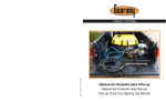
DASY6
User manual
Version 1.00 – July 2010
INDEX
BASIC PROCEDURE................................................................................................................................................ 3
DASY & DANAS SYSTEM ..................................................................................................................................... 4
BOX CONTENT ........................................................................................................................................................... 4
DASY INSTALLATION ........................................................................................................................................... 4
LED ................................................................................................................................................................................... 6
CONFIGURAZIONI HARDWARE ........................................................................................................................ 8
AUTOCALIBRAZIONE.............................................................................................................................................. 9
DOWNLOAD ............................................................................................................................................................... 10
CONFIGURAZIONE ONLINE ............................................................................................................................. 11
CARATTERISTICHE TECNICHE ....................................................................................................................... 12
BASIC PROCEDURE
- Read carefully the instruction before starting to use the system
- Install the telemetry program on the bike
- Identify the configuration parameters for each one of the chosen sensors
- Install the USB driver (required at first connection)
- Configure the hardware parameters through the DANAS2 software
ATTENTION:
In order not to alter the signals to the junction box, UNCONNECT the
DASY inputs if the bike is used with DASY not powered up
ATTENTION:
DO NOT rigidly fasten DASY to the bike.
ATTENTION:
If a previous version of DANAS has already been installed, run the uninstall tool and then
manually remove the ‘Danas’ folder (usually located in C:\Programs) before installing
DANAS2.
ATTENTION:
DASY and DANAS systems have been designed only for use in motorsport race tracks,
and are not homologated for street use.
DASY & DANAS SYSTEM
The data acquisition system produced by I2M srl is composed of two inseparables parts: the acquisition box
DASY6 and the data analysis software DANAS2.
In this document you can find instructions on the installation and use of DASY6 system. Please refer to the
DANAS2 instruction manual for any doubts on installation and use of the software package.
BOX CONTENT
In the DASY6 box you will find:
- telemetry main box
- 10 Hz GPS receiver
- USB cable
- 2 yd, 5 poles Binder cable
- instruction and installation CD
The box content of the DASY (Data Acquisition System) is shown in Figure 1.
We advise to connect the cables for signal acquisition by soldering and insulating. In fact, while Quick Slide
or T-Taps connector are fast and easy ways to join cables, on the long run the connection can fail due to
vibrations or tarnishing.
Fig. 1 – Box content
DASY INSTALLATION
On the back side of the DASY6 junction box there are 4 cables. Two of them end with a PS2 connector, and
are to be linked to a GPS receiver and a miniLAP display (if present). The two PS2 connectors are one male
and one female, so it will be impossible to exchange them by error. The third cable, with a female USB
connector, is used for data download on a pen drive (see the Download chapter). The last cable provides the
power supply. The DASY system is powered with 3 wires: ground +12 V and +12 V key-on. The following
drawing shows the connector pinout. Using the provided connector, link the wires as explained:
1) ORANGE = +12 V key-on
2) BLACK = ground
3) RED = +12 V
Fig. 2 – DASY6 junction box
The black and red cables must be connected DIRECTLY to the vehicle battery, and we advise to include a
500 mA or 1 A fuse in series with the cable to protect both the bike and DASY from any accidental short
circuits. This way, the DASY system will always be powered in order to guarantee the successful conclusion
of write operations even if the system is accidentally turned off. Once the key-on power has been turned off,
DASY absorbs NO power, and so does not cause any battery discharge. The orange wire must be
connected to the key-on power, or to a separate switch, in order to easily turn on or off DASY.
ATTENTION: under NO CIRCUSTANCES disconnect DASY form the battery before the write
operation is concluded (green LED lighted up). Removing power at those times could not only
corrupt recorded data, but could IRREPARABLY damage the memory itself.
DASY is designed with versatility in mind, so it can work with no sensors connected and when the GPS
receiver is inactive.
DASY6 has the following connection:
-
6 analog inputs
2 speed inputs
1 RPM input
5 V output
12 V output
GPS channels
Below you can find the pinout of the Binder 712 connectors used to connect DASY to the signals to be
acquired. The table reports the color of the corresponding wire in the 5-poles Binder cable available from I2M
srl.
Input pinout (as seen from DASY6)
INPUT
1
2
5
3
4
-
-
-
COM
PIN 1
Brown
GND
PIN 2
Grey
L1
PIN 3
Black
L2
DIG
AN1
AN2
GND
GND
GND
+12V
+5V
+5V
Speed1
Analog1
Analog4
PIN 4
Blue
Remote
start
input
RPM
Analog2
Analog5
PIN 5
White
Video
start
output
Vel2
Analog3
Analog6
Analog 1-6: these are 10-bits, 0-5 V analog inputs, to be connected to various sensors such as
throttle position, brake pressure, tire temperature, suspensions…
RPM: this input is specifically intended to record the engine RPMs, obtainable by tapping into the
signal sent by the junction box to the dashboard. Attention: the number of pulses for each engine
turn varies from bike to bike and MUST BE CONFIGURED in DANAS. The pulse voltage on this
input can be as high as 20 V.
SPEED: connect these inputs, for example, to speed sensors on each wheel. These can be ad-hoc
inductive sensors or, for the rear wheel, the signal can be taken directly from a factory-mounted
sensor that counts the RPMs of the pinion or, in some cases, of an internal shaft directly connected
to the pinion. Attention: the number of pulses for each turn varies from bike to bike and MUST BE
CONFIGURED in DANAS.
SYNC. OUT: this output signal is available to synchronize external elements such as a video
recorder. The output voltage is 3.3 V during recording, and 0 V when the system is idle.
REMOTE: this is a synchronization input to instruct DASY when to sample. For example, by
connecting this input to ground via a switch (maybe located near the dashboard) it would be possible
to manually start recording (it would be necessary to configure the system to accept this remote
input as a start; for more information see the hardware configuration section). This input has an
internal pull-up to 5 V.
First of all choose which input are to be connected and choose where to place DASY.
The RPM, Speed and Throttle aperture signals can be taken directly from the signals reaching the
dashboard (the first two) and the junction box (the latter).
LEDs
On DASY’s top side there are three bicolor LED indicators. The LED can emit red, green or orange light.
When the system is switched on, during initialization, all LEDs are light up.
- POWER LED RED : indicates that the system is powered at 12 V and is working correctly, this LED
will always stay on.
- POWER LED GREEN : indicates that the system is powered from a PC through the USB
connection.
-
GPS LED RED : indicates the status of the GPS peripheral. When the GPS is not connected, the
LED is off. The LED is on when the GPS receiver is unable to determine the current position. When
the LED blinks at a 1 Hz frequency the position is valid. Attention: when the satellite signal is weak it
is possible that the GPS receiver detects a valid position, but not a valid speed; in this case the GPS
LED will blink, but the speed figure is unreliable. When the memory card is full, the GPS LED and
the DATA LED will blink alternatively.
-
GPS LED GREEN : blinks to indicate a too low voltage supply. The system will remain locked in this
state until the voltage gets back to normal levels, or the system is turned off through the key-on
voltage.
-
DATA LED GREEN : when on indicates the system is correctly sampling.
-
DATA LED RED : when on indicates the system is communicating with a PC or with the USB pen
drive. Do not disconnect the USB pen drive when the LED is on. When the system is powered by
PC, at first only this LED will light up until a communication is established with the PC software used
to initialize the system.
HARDWARE CONFIGURATION
Before starting the configuration, make sure DANAS2 (refer to the DANAS installation manual) and the USB
driver have been successfully installed on the PC: download and uncompress the driver zip file; connect
DASY6 to the PC through the USB cable; when the operating system asks for the driver, choose the
directory created uncompressing the zip file; then wait for the end of the installation.
Before DASY6 can be used, it is necessary to set the Hardware parameters. For example, it is necessary to
set the sampling frequency for the data and the GPS signal, under which conditions the sampling will start,
and the number of pulses relative to the Speed and RPM inputs.
First of all, configure the COM port on Danas, please follow the instruction on “download” section.
COM Selection: choose the COM port to use for the connection. By selecting this option, the window shown
in figure will appear. Choose the correct COM port through the drop down menu, and confirm be clicking
“OK”. If the correct port is not known, click on “Find”, and the system will automatically choose the first COM
port it finds with an I2M device connected. If the search is successful, just click “OK” to accept the selection.
The parameters can then be configured by connecting directly the system to the PC through a USB cable or
by using a USB pen drive. In both cases it is necessary to follow the procedure detailed in the following. If
the system is connected directly to the PC, use the buttons “Read from DASY6” or “Write to DASY6”,
otherwise choose “Save on USB key” or “Load from USB key”. Before a USB pen drive can be used for
the configuration, it must be prepared by connecting to DASY, when the system is powered on and
not recording data.
The function “DASY6 settings” under the “Settings” menu in DANAS2 allows to set these parameters. The
window shown in figure 3 will open.
When the settings are saved on a USB pen drive, the system will update its configuration as soon as the pen
drive is connected when the system is powered on.
Fig. 3- DASY settings
-
AutoStart: choose which of the inputs can cause the system to start sampling. The sampling can be
started every time that a speed greater than zero is detected (either from a sensor or from the GPS), or
an RPM signal is detected, or manually through a remote signal. The flag “all fulfilled” indicates whether
all the above conditions must be fulfilled at the same time to start recording, or just one of them is
sufficient. It is also possible to specify for how long the conditions must be fulfilled before the sampling is
actually started.
-
Minimum Values: these parameters set constraints for the AutoStart. Here it is possible to set the
minimum speed and/or the minimum RPM that are considered valid for the sampling.
-
Sampling: configures the sampling time. This indicates how much time passes between two
consecutive samples. The inverse of the sampling time is the sampling frequency. In theory, the more
frequent the sampling, the more ‘accurate’ the data. However, a too high sampling frequency will place
too much burden on the system in terms of calculations, and will lead to very large data files. Admissible
values are in the range 2 ÷ 500 (meaning from 0.02 seconds to 5 seconds or, to put it another way, from
50 samples per second to 1 sample every 5 seconds).
The GPS frequency indicates how often GPS data are saved (maximum frequency 10 Hz). When the
BAUD rate menus are enabled, they allow to set the transmission speed towards the GPS receiver and
the display. Attention, the baud rate to the display can not be less than the one to the GPS
receiver. The GPS receiver supplied is set to 38400 and this figure can not be changed.
-
Pulses:
o RPM pulses: Indicates how many pulses are generated by the junction box for every engine
revolution. This figure is usually 1 or 2, depending on the bike make and model, and can easily
be set by trial and error. However, we advise to check the correct setting.
o
Speed 1: Indicates the number of pulses for every pinion revolution. If the speed signal comes
from a sensor connected to the pinion, this figure indicates the number of pulses generated by
the sensor. If the sensor directly measures wheel turns, indicates the number of pulses for every
wheel turn. This figure varies greatly form bike to bike, and can vary from 1 to 30 or 40; it is
therefore very difficult to set this value correctly by trial and error, and we advise to check the
correct setting.
AUTOCALIBRATION
If the correct value for the number of pulses for every pinion revolution is not known, DANAS2.x offers a
handy tool that takes advantage of the capabilities of both DANAS2 and DASY: this procedure uses
DANAS2 to instruct DASY to record the data that are to be used for the calibration, and then DANAS2 will
process the data and give the correct value.
The procedure is very simple, and the tool will guide you step by step; however, the proper procedure is
reported below for the sake of completeness.
Fig. 4- Autocalibration tool startup screen
1) Connect a USB pen drive to the PC and select from the “Settings” menu the Autocalibration tool
2) Select the file “Data.txt” on the pen drive (if the file is not present, connect the pen drive to DASY in
order to create it)
3) Remove the pen drive from the PC using the proper function of the operating system (for example
“Safely remove hardware” in Windows)
4) Connect the pen drive to DASY and turn on the dashboard, but DO NOT START THE ENGINE
5) The power-on LED on DASY will now blink
6) Manually force the back wheel to rotate by an integer number of turns (the greater the number, the
more precise the measure will be; however, the turns must be more than 10)
7) For every turn, the green LED will light up for each pulse, and will remain on for the whole pulse
duration
8) After finishing the established number of revolutions, keep the wheel still for at least 10 seconds: the
power-on LED will again start to blink
9) Disconnect the pen drive from DASY
10) Insert the pen drive on the PC
11) Insert the number of turns actually completed
12) DANAS2 will calculate the correct number of pulses for every pinion revolution
DOWNLOAD
It is possible to download the data in two different ways:
via an USB pen drive
by connecting DASY to a PC (after having installed DANAS2 and the USB driver)
When using a pen drive, it is sufficient to connect the pen drive to DASY. The system will create a new file
containing all the new data. We advise to use a pen drive equipped with an LED, in order to easily determine
the end of the write operation (usually the LED blinks when the pen drive is written to, please verify the LED
behavior with a PC before use with DASY).
Downloading to the pen drive will start automatically when the pen drive is inserted, the system is powered
up and the dashboard is on (key-on power to 12 V). To stop the download, just turn off the dashboard, and
the system will stop downloading data. The created file will not be valid, and we advise to delete it.
When using a direct connection to a PC instead, use the “Online” menu in DANAS2.
Fig. 5 – Online Menu
-
COM Selection: With this option, it will be possible to choose the COM port to use for the connection.
By selecting this option, the window shown in figure 6 will appear. Choose the correct COM port through the
drop down menu, and confirm be clicking “OK”. If the correct port is not known, click on “Find”, and the
system will automatically choose the first COM port it finds with an I2M device connected. If the search is
successful, just click “OK” to accept the selection.
Fig. 6 – COM selection
-
Data Download: with this option it will be possible to download the data from a device, or erasing its
memory. By selecting this option, the window shown in figure 7 will appear. Select the correct device and
click on “Connect”. Once the connection has been established, it will be possible to download the data, by
clicking on “Download”, or to erase the memory by clickng on “Format”. Checking the box “Save on file”
allows to specify a file name for the saved data (the file name must be chosen before downloading the data).
Fig. 7- Data Download
By clicking on “Preview”, it will also be possible to download a list of all the sessions recorded by the
system and still present in its memory.
Figure 8 shows a typical window showing a few sessions. If the GPS is present, for each session the
track name (if recorded), and the date and time will be listed.
Moreover, it is possible to filter only the sessions of interest, and then open all the sessions listed or only
those selected.
Fig. 8 – Data Download
ONLINE CONFIGURATION
Using DANAS2 it is possible to connecting directly to DASY in order to show its input configuration in real
time.
Connect DASY to the PC using the cable provided and power up the system.
Select the “On-Line Connection” option from the “Online” menu in DANAS2. First of all, click on “Connect” to
connect to the device. The window has two panels, one for the analog inputs, and the other for digital.
Fig. 9 – Digital inputs DASY configuration
Fig. 10- Analog inputs DASY configuration
Both panels are divided in three sections:
• Settings: here DANAS will show all the configuration parameters read when DASY is connected
(hardware parameters)
• Raw Data: the raw data acquired through DASY
• Processed Data: the data processed using the configuration parameters
To acquire the data, there are two buttons:
• Sample: carries out a single sampling through DASY and shows the acquired data (both raw and
processed)
• Continuous Sampling: keeps on sampling the data through DASY and shows the data, both raw ad
processed, in real time, updating them about once per second.
It is possible to manually change the parameters and immediately se the effect of the change on the
processed data by clicking on “Apply”.
TEHCNICAL SPECIFICATIONS
Power supply: 12-16 V
Maximum sampling frequency: 100 Hz per channel (except for GPS)
Size: 152 x 78 x 24 mm
Weight: 140 g + 90 g (GPS)
Current draw: 200 mA
Maximum current supply per sensor: 20mA
Digital inputs:
Maximum voltage recognized as low logical level = 1 V
Minimum voltage recognized as high logical level = 4 V
Maximum input voltage = 14 V
DASY does not change in any way the signals present at its inputs, since all are high impedance inputs.
However, the input impedance can decrease to about 2 kΩ when DASY is turned off. In some cases, this low
value can affect the signal coming from the various sensors on the bike. Therefore we advise to disconnect
DASY from the sensors when not in use.
ATTENTION: every connector has both a ground pin and a 5 V pin; these two pins MUST NOT BE
CONNECTED if the signal comes from an already powered sensor. Otherwise there will be short circuits!
The 5 V pins are intended to power, for example, the potentiometers on the forks that are not already
powered.