Transcript
ISCOM005-0704
Mod. LSM-01
Vemer S.p.A.
I - 32032 Feltre (BL) • Via Camp Lonc, 16
Tel +39 0439 80638 • Fax +39 0439 80619
e-mail: [email protected] - web site: www.vemer.it
L
3
N
4
45
88
L N
1
2
230V~
16A/230V~
L
3
N
4
60
18
55
Manuale d’Uso
User Manual
INSERITORE AUTOMATICO LUCE SCALE ELETTROMECCANICO
Leggere attentamente tutte le istruzioni
AUTOMATIC ELECTROMECHANICAL STAIR LIGHT SWITCH
Read all the instructions carefully
■ Il Timer LSM-01 è un dispositivo di comando elettromeccanico
destinato ad operare in ambienti domestici e similari con grado di
inquinamento normale.
■ The LSM-01 timer is an electromechanically controlled device
designed for household and similar operation with normal pollution
levels.
AVVERTENZE DI SICUREZZA
SAFETY WARNINGS
■ Per garantire il grado di sicurezza previsto dal dispositivo
occorre attenersi alle seguenti prescrizioni:
1) Seguire scrupolosamente gli schemi di collegamento per
installare lo strumento.
2) Prima di accedere ai morsetti assicurarsi che i conduttori da
collegare allo strumento non siano in tensione
3) Assicurarsi che il quadro elettrico nel quale deve essere
inserito l’ apparecchio sia tale da garantire, dopo
l’installazione, la inaccessibilità ai morsetti.
■ To guarantee the safety levels designed for the device,
proceed as follows:
1) Follow the connection diagrams to the letter when
installing the instrument.
2) Before touching the terminals, make sure the connecting
wires to the instrument are not powered.
3) Make sure the terminals of the electric panel in which
the appliance is to be inserted will be inaccessible after
installation.
■ NOTA
- Il cablaggio del quadro deve essere eseguito in conformità con
quanto previsto dalle Norme CEI.
- Non alimentare o collegare lo strumento se qualche parte di
esso risulta danneggiata.
■ NOTA
- The panel should be wired in accordance with the EN
standards.
- Do not power or connect the instrument if any part of it
is damaged.
CARATTERISTICHE TECNICHE
TECHNICAL SPECIFICATIONS
•
•
•
•
•
•
•
•
•
•
•
•
•
Alimentazione: 230 V AC ± 10% 50 Hz
Range di temporizzazione: da 45 s a 7 min
Temperatura di funzionamento: -10 °C ÷ +50 °C
Portata contatti:
- 16 A 230 V~ su carico resistivo
- 4 A 230 V~ su carico induttivo
Utilizzo del dispositivo con collegamenti a tre o quattro fili
Corrente disponibile per pulsanti luminosi: 50mA
Dispositivo di classe II
Grado di protezione morsetti: IP20
Comando manuale tramite selettore a due posizioni:
= Automatico (temporizzato)
= Automatic (timed)
= Sempre acceso
= Always on
• Contenitore 1 modulo DIN
• 1 DIN module container
LEGENDA
LEGEND
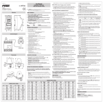
A) Dimensioni (mm)
B) Schemi di collegamento
C) Installazione
A) Dimensions (mm)
B) Connection diagrams
C) Installation
ISTRUZIONI PER L’ INSTALLAZIONE
INSTALLATION INSTRUCTIONS
Modalità di installazione:
• Collegare l’apparato all’impianto secondo lo schema prescelto (B).
• Ruotare il selettore (C1) posto sul lato del dispositivo nella posizione
corrispondente al collegamento a tre (B1) o quattro fili (B2).
• Lo schema a quattro fili (B2) è caratterizzato dal fatto che i pulsanti
ed il carico hanno collegamenti indipendenti.
Installation method:
• Connect the appliance to the electrical system using the
diagram selected (B).
• Turn selector switch (C1) on the side of the appliance to the
position corresponding to three (B1) or four wire (B2) connection.
• With the four wire layout (B2), the pushbuttons and load
have independent connections.
MODALITA’ DI UTILIZZO
• Predisporre il selettore (C2) nella posizione prescelta
(carico sempre connesso o temporizzato)
• Regolare il tempo di inserzione tramite la rotella (C3) posta sul
frontale (se si è scelta la posizione di funzionamento temporizzato)
• Premere uno dei pulsanti collegati per iniziare la temporizzazione
• E’ sufficiente premere nuovamente uno dei pulsanti per prolungare
la temporizzazione
1
2
230V~
16A/230V~
•
•
•
•
•
Power supply: 230 V AC ± 10% 50 Hz
Timing range from 45 s to 7 minutes
Operating temperature: -10 °C ÷ +50 °C
Contact capacity:
- 16 A 230 V~ on resistive load
- 4 A 230 V~ on inductive load
The device can be used with three of four wire connections
Luminous pushbuttons can de used: max 50mA
Class II equipment
Terminal protection level: IP20
Manual control by two position selector:
INSTRUCTIONS FOR USE
• Set the selector switch (C2) to the position required
(load always connected or timed)
• Adjust the activation time using the roller (C3) on the front
panel (when using the timed operating function)
• Press one of the pushbuttons connected to start the timing
• Simply press one of the pushbuttons again to prolong the timing
NORME ARMONIZZATE DI RIFERIMENTO
HARMONISED REFERENCE STANDARDS
■ La conformità alle Direttive Comunitarie:
73/23/CEE mod. da 93/68/CEE (Bassa Tensione)
89/336/CEE mod. da 92/31/CEE e da 93/68/CEE (EMC)
è dichiarata con riferimento alle seguenti Norme armonizzate:
■ PER LA SICUREZZA: CEI EN 60669-2-3
■ Conformity with Community Directives:
73/23/EEC, modified by 93/68/EEC (low voltage)
89/336/EEC, modified by 92/31/EEC and 93/68/CEE (EMC)
is declared with reference to the following harmonised
standards:
■ FOR SAFETY: EN 60669-2-3:
■ PER LA COMPATIBILITA’ ELETTROMAGNETICA:
CEI EN 55014-1
CEI EN 55014-2
■ FOR ELECTROMAGNETIC COMPATIBILITY:
EN 55014-1
EN 55014-2