1
Via L.. Da VINCI, 100, 50028, Tavarnelle V.P – FIRENZE – Tel. +39 055 80 71 267 /118 Fax. + 39 055 80 71 338
E‐mail [email protected] www.telegroup.it
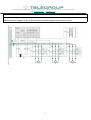
3 ‐ CONNECTION
1. The C.T. secondary must be earthed.
2. Power the equipment with cables of a section suitable for the label power specifications.
3. Power Supply: Three phase with neutral for equipment with a power from 7.5 to 27.5 kvar ‐ Three phase without neutral
for equipment over 27.5 kvar with a power of 400 volts.
4. Anchor the power supply cables to the mains switch.
IMPORTANT!
In the event that the panel were to be shut down during operation, make sure that all of the batteries have been disengaged before
opening the mains switch.
4‐ CHOICE, LOCATION AND CONNECTION OF THE CURRENT TRANSFORMER (CT):
C.T. calibration with 5/A secondary, (to be provided by the client) must be calculated based on the average current circulating in the
plant, independent of the power factor correction, keeping in mind that the range of measurement of the regulator current goes
from 8% to 110% of the C.T. current. Therefore, this condition must be satisfied.
Ex: there is a circulating current of 200/A; a C.T. must be chosen the current of which is between: 2500 A (8% of 2500=200/A) and
180A (110% of 180 A= 200 /A). It is a good rule to install a C.T. with twice the primary current of that which is actually circulating.
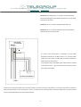
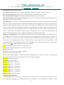
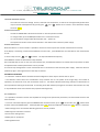
The C.T. must be located upstream of the loads and the bypass that
powers the power factor correction panel. All in all one must “consider”
MAINS
L1 L2 L3
both the inductive loads of the users as well as those of the capacitance
of the capacitors. In the bypass that powers the power factor correction
T.A..../5 A
panel, the phase corresponding to that where the C.T. is installed must
be anchored to the central terminal of the switch. Since the phases that
voltmetrically power the regulator must be different from the phase
where the C.T. is installed and in that in our panels this signal is drawn on
the two lateral phases, it is obligatory that the corresponding phase be
T.T.
anchored, to the same one where the C.T. was installed, on the central
terminal of the switch. This condition may be easily verified with the use
QUADRO RIFASAMEN TO
of a voltmeter, measuring, between the phase where the C.T. was placed
and the phase anchored to the central terminal of the switch of the
LOAD
automatic power factor correction panel: the voltage must be “0”. The
location of the C.T. is fundamental for the proper use of the equipment.
The relative diagram is found in the figure to the side.
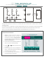
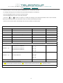
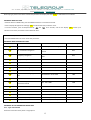
In the table below some possible positions of the
MAINS
C. T.s that are faulty:
L1 L2 L3
3