1
P-FOCUS
IEF Strip System
Electrophoretic
WorkStation-1
2
Index
1. Safety information .................................................................................................. 4
2. Function and description......................................................................................... 5
3. Isoelectric focusing applications............................................................................. 6
3.1 Sample preparation: .............................................................................................. 8
3.2 Rehydrating and loading IPG strips ...................................................................... 9
4. Low voltage electrophoresis applications (for EWS-1 only) ............................... 14
5. IEF Control Software manual ............................................................................... 15
5.1 General informations about cursor keys ............................................................. 16
5.2 Plate connectors (for EWS-1 only) ..................................................................... 16
5.3 How to turn on the system .................................................................................. 17
5.4 How to use the system ........................................................................................ 17
5.5 Main Menù.......................................................................................................... 17
5.6 IEF system .......................................................................................................... 17
5.6.1 Operating Stage ............................................................................................... 18
5.6.2 Program Setup ................................................................................................. 22
5.6.3 Setup ................................................................................................................ 25
5.7 Low voltage power supply (for EWS-1 only) ................................................... 26
5.7.1 Initial informations .......................................................................................... 26
5.7.2 Parameters Setting ........................................................................................... 26
5.7.3 Start and pause ................................................................................................. 28
5.8 Error messages .................................................................................................... 29
6. Troubleshooting .................................................................................................... 31
7. Recipes.................................................................................................................. 32
8. Technical specifications........................................................................................ 33
9. Ordering information ............................................................................................ 34
10. References........................................................................................................... 36
3
1. Safety information
WARNING !
The Warning sign highlights an instruction that must be strictly followed
in order to avoid personal injury. Be sure not to proceed until the
instructions are clearly understood and all stated conditions are met.
The Electrophoretic WorkStation (EWS-1) has been tested and complies with the IEC
61010-1 (EN 61010-1) Electrical safety standard.
Extreme caution should be exercised when operate because this instrument can develop
higher voltage and current sufficient to produce a lethal shock.
Read this entire manual before using the instrument and use it only according to the
manufacturer’s instructions.
Before using to make sure that:
The instrument must always be used with the earth lead of the power cord
correctly grounded to earth at the mains outlet.
To permit sufficient cooling, ensure that the vents in the over and under of the
instruments are not covered.
To use the instrument only indoor, not extreme humidity (above 95%). Avoid
condensation by letting the unit equilibrate to ambient temperature when taking
the power supply from a colder to a warmer environment.
Keep the instrument as dry and clean as possible. Wipe regularly with a soft
damp cloth.
Let the power supply dry completely before use. If wetted, unplug the power
supply until the instrument is dry.
Use only undamaged electrical wire and equipment specified for the voltages you
will use.
High voltage electrical wires should be in accordance with IEC 1010-2-031:1993.
All equipment connected to high voltage should be in accordance with IEC 10101:1993.
4
2. Function and description
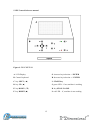
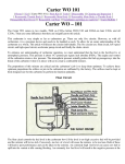
Electrophoretic WorkStation–1:
The Electrophoretic WorkStation-1 (EWS-1) is an innovative apparatus in the
field of electrophoresis (Millioni et al., 2010). It is a versatile modular system
which offers a solution for analytical or preparative separations of proteins and
peptides by isoelectric focusing (IEF) on immobilized pH gradients (IPG strip),
protein SDS-PAGE, DNA electrophoresis. For IEF applications, this instrument
can accommodate i) a shorter tray with twelve channels to perform IEF on up to
24 cm long IPG strips; ii) a longer tray with six channels to perform IEF on up to
42 cm long IPG strips (or shorter IPG strips of appropriate pH ranges positioned
end-on-end).
The EWS-1 (figure 1) includes the following features:
• two integrated power supplies:
1) High voltage power supply for IEF (up to 15000V and 2mA).
The high voltage power supply is able to deliver a field strength of up to 15000 V,
a necessary feature for utilizing IPG strips longer than 25–30 cm. In fact, with
such a power supply, it is possible to perform IEF on very long immobilized pH
gradients at a voltage gradient of 330 V/cm, a value comparable to present-day
power packs operating at 8000 V on 24 cm long strips.
2) Low voltage power supply (up to 250V and 450mA).
A detailed description of the characteristics of these power supplies is reported in
paragraph 8.
• temperature control by integrated Peltier elements.
• the integrated control software, with up to ten user-defined IEF protocols, each
with up to ten steps per protocol. Programmable functions include: rehydration time,
5
platform temperature, current limit, voltage limit for each step, voltage gradient or
step and step duration.
• a set of strip tray for IPG strips rehydration, running and equilibration. These trays
differ in length and number of strip channels.
The EWS-1 must be placed on a flat surface and the safety lid must be properly
closed before power is applied.
Figure 1: Electrophoretic WorkStation-1: 1) connectors of the high voltage module (IEF system); 2)
connectors of the low voltage module; 3) safety lid; 4) control panel.
P-Focus
The only difference between the P-Focus and the EWS-1 is the absence of the low
voltage module.
3. Isoelectric focusing applications
Isoelectric focusing (IEF) is a technique for separating molecules by their electric charge
differences. It is a type of zone electrophoresis, that takes advantage of the fact that
overall charge on a protein is a function of the pH of its surroundings. Proteins carry
charged groups on their surface. Each of these functional groups has a pK, which
corresponds to the pH at which half of the members of that group are protonated. Above
6
or below the pK, that group can be considered respectively fully protonated or
deprotonated. Thus, as the pH changes, the net charge on a protein's surface will change.
The isoelectric point (pI) is the pH at which the net charge of the protein is zero. With the
presence of a pH gradient in the IEF method, the protein will migrate to the position
where its charge is zero: a protein with a positive net charge will migrate toward the
cathode until it meets its pI, while a protein with a negative net charge will migrate
toward the anode until it meets its pI. The matrix used in this process has a high porosity
to eliminate any “sieving effect”, which would cause differing migration rates for
proteins of different sizes. If the protein diffuses away from its pI, it will regain its charge
and migrate back.
A reproducible pH gradient is crucial for successful IEF. In order to overcome the
limitations of carrier-ampholyte-generated pH gradients (e.g. the so-called cathodic drift
and plateau phenomenon) immobilized pH gradients (IPG) were developed in 1982. IPGs
are based on the bifunctional Immobilines reagents, which are acrylamide derivatives.
Their general structure is CH2=CH-CO-NH-R, where the group R contains either an
amino or a carboxyl or group, and forms a series of buffers with different pK values,
between 1.0 and 13. Since the reactive end is co-polymerized with the acrylamide matrix,
the pH gradients are stable and reproducible also during extended IEF runs. The
preparation of IPG strips on a plastic backing offer an optimal solution for convenient
handling. The strip length depends on the size of the second-dimension gels to be used,
with longer strips and larger gels providing higher sample capacity and resolution.
The main problem to further increase the resolution of IPG strip is the technical difficulty
associated with establishing reproducible density gradients over distances longer than 24
cm. This issue could be avoided, by using two or three strips (the number depending on
the length of individual strip), with the appropriate pH ranges positioned end-on-end in
series (see paragraph 3.2).
7
3.1 Sample preparation:
Actually, a unique 2-DE protocol of sample preparation that can be applied to all types of
samples does not still exists. In fact, although several standard protocols have been
published, these methods have to be adapted and further optimized for the type of sample
(e.g. microbial mammalian cells) to be analyzed, as well as for the type of proteins of
interest (e.g. soluble or insoluble membrane
proteins). However, some general
recommendations can be given:
desalt the sample or prepare the sample so that the salt concentration is less than
10 mM. Salt may be removed either by (spin)dialysis or by precipitation of
proteins (e.g. by TCA or organic solvents);
samples containing urea must not be heated (< 37°C) in order to avoid the
carbamylation of the proteins by isocyanate formed in the decomposition of urea.
Isocyanate covalently modifies lysine residues, thus inducing a change in
isoelectric point;
since IEF in the presence of 8M urea at low temperatures is not suitable due to the
formation of urea crystals, optimum focusing temperature is 20°C;
proteases present within samples have to be inactivated by using protease
inhibitors;
delipidation can be obtained by extraction with organic solvents, such as ethanol
or acetone;
unless present at low concentrations, nucleic acids have to be removed by
TCA/acetone protein precipitation or by protease-free RNAses and DNAses
digestion;
the most used sample solubilization buffer are the modified O’Farrell lysis buffer
(9 M urea, 2-4% CHAPS, 1% DTT, 2% v/v carrier ampholytes),
or the
thiourea/urea lysis buffer (2M thiourea, 5-7M urea, 2-4% v/v CHAPS and/or
sulfobetaine detergents, 1% DTT, 2% v/v carrier ampholytes);
the minimum protein concentration should not be less than 0.1 mg/ml, and
optimum concentration is 1-5 mg/ml;
long-time storage of solubilized protein sample is possible in a freezer at -80°C
preferred. Repeated freezing and thawing of the sample must be avoided. It is
recommended to make aliquots of the sample and thaw only once;
8
due to the high dynamic range and diversity of any proteome, it is highly
recommended to perform a pre-fractionation step to reduce the complexity of the
sample.
Over the past few years, IEF has gained increasingly interest also as a peptide
fractionation method (Eriksson H. et al., 2008; Fraterman S et al., 2007; Cargile BJ et
al., 2004; Cargile BJ et al., 2005; Geiser L et al., 2011; Heller M et al., 2005). In fact,
apart from being an excellent tool for separating complex mixture of peptides, peptide
IEF has high reproducibility, is compatible with other fractionation techniques for
multistep protocols and can provide the additional information of experimental pI that
can aid in the protein and post-translational modification identifications. In this approach,
the IPG gel strip is cut into sections and then the focused peptides can be extracted and
analyzed from all the gel sections (Cargile BJ et al., 2004). One advantage in working
with peptides is that peptides possess greater solubility than proteins. Xiao et al. (2004)
demonstrated the efficacy of ampholyte-free peptide autofocusing, avoiding sample
losses due to ampholyte removal strategies. The most used solubilization buffer for
peptide IEF is 8 M urea, 1% DTT, 5% v/v glycerol.
3.2 Rehydrating and loading IPG strips
IPG strips must be rehydrated prior to IEF. Usually, protein sample can be
applied either by including it in the rehydration solution or by applying it directly
to the rehydrated IPG strip via sample cups. We suggest to include the sample in
the rehydration solution because, respect to the cup loading approach, this method
is technically simpler and eliminates the risk of precipitate formation, which often
occurs at the application point of cup loading. The rehydration stock solution can
be diluted no more than 1/8 by sample addition. The amount of protein that can
be added is dependent upon the length of strip, the pH range and the detection
method to be used.
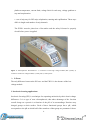
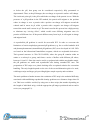
Select the equilibration tray (figure 2) corresponding to the IPG strip length
chosen for the experiment. Wash the extensively with double distilled water to
9
remove residual protein. The equilibration tray must be completely dry before
use.
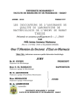
Figure 2: Equilibration strip tray for 7 cm long IPG strips. Other different trays are available depending on
the different length of IPG strips.
Deliver the solution slowly at a central point in the rehydratation strip tray
channel and remove air bubbles.
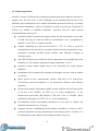
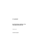
Remove the protective cover from the IPG strip (figure 3).
Figure 3: Remove the protective plastic (2) from the IPG strip (1).
10
Lay down the IPG strips gel-side down into the rehydration solution. Wet the
strip by sliding it back and forth along the tray channel. Remove any large air
bubbles. For typical composition of rehydration solution, see paragraph 10.
Completely cover the IPG strips with the Cover Fluid, and allow the strips to
rehydrate. The Cover Fluid is used to minimize evaporation and urea
crystallization. A minimum of 10 hours is required for rehydration; overnight is
recommended. Alternatively, the rehydration can be programmed as the first step
of the IEF protocol. This is convenient if temperature control during rehydration
is a concern, or if a low voltage is applied during rehydration.
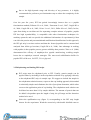
Wash the IEF tray extensively with double distilled water to remove residual
proteins. The tray must be completely dry before use.
Figure 4: IEF tray for 42 cm long IPG strips or for shorter IPG strips of appropriate pH
ranges positioned end-on-end.
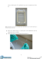
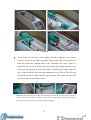
Put the IEF tray on the cooling plate and connect the electrodes to the high
voltage module (figure 5, step 1-4).
11
Figure 5
At the bottom of the teeth of the sliding electrodes, platinum wires provide
electrical contact to the small rectangular paper bridges that must be placed at
both the anodal and cathodal ends of the rehydrated IPG strips (figure 6).
Moistened prior to use with deionized water, these paper bridges absorb excess
water, salts, and proteins with pI values that lie outside the pH range of the IPG
strip. Transfer the IPG strips from the rehydration to the IEF tray. The IPG strip
acrylamide must be in contact with the paper bridges. The acidic end of the IPG
gel strips must face towards the anode.
Figure 6: Positioning the paper bridge, the electrode and the IPG strip. These operations must be
done at both the ends of the strip. Remove excess water from the paper bridges by blotting with
tissue paper: paper must be only wet, not saturated or dripping.
12
The sliding electrodes are fully adjustable to suit the length of strips. Since it is
very difficult to produce more than 24 cm long pH gradients, shorter IPG strips of
appropriate pH ranges can be positioned end-on-end (Poznanovic S et al., 2005).
During IEF, proteins efficiently migrate from one IPG to another by traversing
buffer-filled porous bridges between the serial IPGs. A variety of materials can
function as bridges, including paper or polyacrylamide gels or even the same IPG
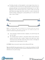
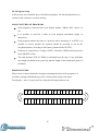
strips, as shown in figure 7.
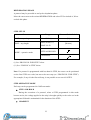
Figure 7: A schematized example to show the loading of two (A) and three (B) IPG strips. The plastic
backing film is indicated by a heavy border on the IPG strips. Arrows indicate the position of the
electrodes. The small blue rectangles indicate the paper wicks.
After positioning of both the electrodes, completely cover the IPG strips with
the Cover Fluid.
The instrument must be placed on a flat surface and the safety lid must be
properly closed before power is applied. Turning on the mains power switch
located on the side of the EWS-1 and of the P-Focus activates a self diagnostic
program that runs for approximately 10 seconds.
CAUTION! Always wear protective gloves when working with IPG strip.
Note: After IEF, IPG strip can be stored at -20 °C or lower for several days. For 2-DE
applications, SDS-strip equilibration must be performed immediately prior to the seconddimension run, never prior to storage.
13
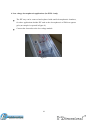
4. Low voltage electrophoresis applications (for EWS-1 only)
The IEF tray can be removed and replaced with small electrophoretic chambers,
for other applications besides IEF such as the electrophoresis of DNA on agarose
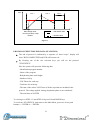
gels (an example is reported in figure 8).
Connect the electrodes to the low voltage module.
Figure 8
14
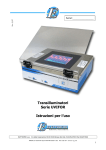
5. IEF Control Software manual
Figure 9: DESCRIPTION
A: LCD Display
G: increase key/selection + / ENTER
B: Control keyboard
H: decrease key/selection ─ / ENTER
C: key LEFT (◄)
I: START key
D: key UP (▲)
J: green LED – if on, machine is working
E: key DOWN (▼)
K: key STOP / PAUSE
F: key RIGHT (►)
L: red LED – if , machine is not working
15
5.1 General informations about cursor keys
The cursor keys (UP, DOWN,LEFT and RIGHT) are used to navigate through the
display. The current cursor position is indicated by highlighting text.
Increase/selection (+ / ENTER) and decrease/selection (─/ ENTER) key are used
to confirm (for example, if you want to exit from an application and the cursor
was placed on"EXIT"). Also is used to change parameters. In most cases, to
quickly change a parameter, simply hold down the button.
The START and STOP/PAUSE keys are active only in "OPERATING STAGE",
respectively to start or resume execution of a protocol or to stop it temporarily or
permanently.
To ensure the execution of these actions, you must be press button for a longer
time that the normal.
5.2 Plate connectors (for EWS-1 only)
The position of high and low voltage connectors is schematically reported in figure 10.
Figure 10
16
5.3 How to turn on the system
Make sure that the power cord is correctly plugged (100-250, 50-60Hz). Turning on the
mains power switch located on the side of the EWS-1 and of the P-Focus activates a self
diagnostic program that runs for approximately 10 seconds. If any failure is detected, call
Elettrofor service. Press the switch on the right side of the device. After turned on, the
system will check and test all the components for a few seconds. The LCD display will
show the company logo, both LEDs will be lit (see figure 9: J and L), and an audible
signal will be activate. When test operations will be complete, display will show "MAIN
MENU ". To turn off the system simply press the switch on the right.
5.4 How to use the system
The EWS-1 Electrophoresis WorkStation has two internal power supplies that can be
used in 2 different exclusive mode:
1) High voltage power supply for isoelectric focusing system IEF (up to 15000V and
2mA)
2) Low voltage power supply for normal electrophoresis (up to 250V and 450mA)
5.5 Main Menù
Allowed selections in the MAIN MENU screen:
1.IEF SYSTEM (section relating to the high-voltage)
2.POWER SUPPLY (low-voltage power supply section)
Using UP and DOWN arrow keys, move to the desired menu item. To confirm, press one
of the selection key button.
5.6 IEF system
In this section you can access all functions for general setup, protocol setup and the use
of the high voltage power supply.
In the menu, "IEF MENU" the following selections are allowed:
- OPERATING STAGE
- PROGRAM SETUP
- SETUP
Use the UP and DOWN arrow keys, move to the desired menu item. To confirm, press
one of the selection key button.
17
5.6.1 Operating Stage
MAIN FEATURES
In this section you can choose and run a program.
Before and during the execution of a program you can change the value of some
parameters. This changes will be operative only during the current session,
because data is not stored on memory.
The screen shows the name of the program, as it was set in the SETUP
PROGRAM section for the specific program selected.
The REHYDRATION PHASE can be included or excluded from the current
program, in which case you can change the duration time.
Before running selected program you must set the strip number that will be used
(STRIP NO.) for the current session.
Each step include a voltage value (VOLT), a duration time (TIME), an operative
mode (MODE) and a remaining time (REMAIN.TIME), which indicate how
much time is left to ending the current STEP.
For each program, the system will calculates the total duration (under theTIME
column) and the total remaining time (REMAIN below the column TIME). These
are the two TOTAL TIME and are composed with time associated to the STEP
and the rehydration phase (if included).
PROGRAM SELECTION
Move the cursor key on the program number (NR PROG.) and use the + and ─ to select
the desired number program.
REHYDRATION PARAMETER
Before the execution of a program. Alongside “REHYDRATION”, total
duration of rehydration phase is displayed. If the values of hours and minutes are
different from zero, this means that the program is running with the rehydration
time equal to the previous time set up. If the values of hours and minutes are
00:00, the rehydration phase is not included and protocol will begin with the “
first non-zero STEP”.
18
During the execution of a program. In this case, alongside ”REHYDRATION”,
will be displayed the value of remaining time. If rehydration phase is included
and is currently running, you have the possibility to change the remaining time.
If this time is set up at 00:00, it means that you want to end prematurely the rehydration
phase, this change is implemented after few seconds. Instead, If the remaining time is
increased, this is only possible if the total duration of rehydration phase does not exceed
the maximum allowed: Length + Total Elapsed Time = Time Remaining <99:59.
STRIP NUMBER AND POWER LIMITATION
Before starting a program, you must set the strip number (STRIP N O.) You can
enter values between 1 and 12.
When setting this parameter, a check to the maximum power required is
automated made in relation to the maximum current per strip set in the “SETUP”
section. It would be possible that the maximum number of strip number set is less
than 12.
PARAMETERS VIEWING AND CHANGING
On entering this section, you will see the table containing STEP 1 to 5.
To see next 6 / 10 STEP, move the cursor in one step 5 parameters and press
DOWN, or move to “EXIT” and press the UP button.
In addition, during the execution of a protocol, the cursor can be moved only
within the range that goes from STEP (or rehydration) up to the first “zeroSTEP”.
Changing the STEP parameters: if protocol is not running, for each step you can
change the voltage (VOLT), and if this is different from zero, the values of step
duration (TIME) and the operative mode (MODE).
During the execution of a protocol is possible to change the voltage (VOLT), and
if this is different from zero, the remaining time (REMAIN.TIME)
PROTOCOL EXECUTION
To start a program, press START button for a few seconds, red LED will turn off
and green LED will lights up.
19
Two flashing arrows indicate the exact point of protocol execution.
Throughout the execution of the program, lid condition is constantly monitored,
and when open, an intermittent “beep” sound will be audible and the message
"NOT LATCHED LID” will be displayed. In this situation, voltage on strip is
cut-off and the plate temperature is no longer controlled. To resume the current
program running you should close the lid and press START button.
When a protocol is running the display shows alternately a row containing the
program identification number and name, a row that shows the instantaneous
values of voltage (VOLT) and current per strip ("CURRENT") and a line which
shows the cumulative value of volts / time allocated since the begin of a protocol.
PROTOCOL PAUSE AND STOP
When a protocol is running, you can pause the system by pressing the STOP / PAUSE.
In this situation, voltage on strip is cut-off and the plate temperature is controlled.
When pause a protocol, it displays the word "PAUSE".
To exit the pause and resume the execution of the program, press START button, but if
you press another time the STOP / PAUSE, the program end.
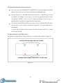
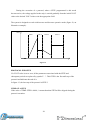
CURRENT CONTROL
When a protocol is running an automated check is constantly made to the current.
The maximum current allowed through the strip is given by the product of the number of
strip (STRIP N°.) and the value of current per strip (CURRENT/STRIP).When system
detects that the amount of current flowing through the strip is greater than the desired
maximum current, the applied voltage is decreased to the value that satisfies the
constraint of current:
Current that crosses the Strip ≤ Strip Current * Number of Strip
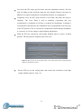
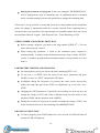
See figure 11 for example.
The voltage limitation due to the current control is highlighted by the flashing of an
asterisk "*" written next to "VOLT".
20
VOL
T
STEP 1
STEP 2
STEP 3
t
Max voltage value:
“Current per Strip x Strip
number”
= real limited value
= desired value
Figure 11
PROTOCOL EXECUTION END DATA (STATISTICS)
The end of protocol is indicated by a sequence of “three beeps”, display will
show "RUN COMPLETED" and LED will become red.
By Pressing one of the two selection keys you will see the protocol
"STATISTICS".
Here the system will report the following data:
- Identification program number
- Name of the program
- Rehydration phase total lenght;
- Number of Strip
- VOLT/hour for each step
- Total time for each step
- The sum of the values VOLT/hour of all the steps that are included in the
protocol. The voltage applied during rehydration phase is not considered.
- The total time of all STEP
To viewing over STEP 1 /5 and STEP 6/10 press UP and DOWN keys.
To exit from “STATISTICS “and return to the Main Menu, press one of two push
buttons (+ / ENTER or - / ENTER).
21
5.6.2 Program Setup
In this section you can define up to 10 different programs. All data and parameters set
written in this section are saved in memory.
MAIN FEATURES OF PROGRAMS
Each program is characterized by an identity number "PROG. NR." (from 1 to
10).
It is possible to associate a name to each program (maximum length: 16
characters).
Each program contains the data of a protocol with a maximum of 10 STEP. it is
possible to choose whether the protocol should be preceded or not by the
rehydration phase (according to the features planned in the SETUP).
Each step is composed by a voltage (VOLT), a duration (TIME) and an operative
mode (MODE) values.
The total duration (TOTAL TIME) is calculated how the sum of any individual
step length (included in the protocol) and the length of the rehydration phase (if
included).
PROGRAM NAME
When cursor is moved inside the rectangle containing the name of the program, it is
possible to change individually any of the 16 letters that compose the name.
Pressing the + and ─ let you scroll in a loop the following character sets:
A B C D E F G H I
9
8 7
6
5 4 3
2
22
J K L M N O P
1 0 ─
Q R
S
Z Y X W V U T
REHYDRATION PHASE
A protocol may be preceded or not by the rehydration phase.
Move the cursor next to the written REHIDRATION and select YES to include it, NO to
exclude this phase.
STEP SET-UP
Parameter
VOLT – step voltage
TIME – step lenght
MODE – operative mode
Range set
Measure Unit / Simbol
10 ÷ 15000 (*)
MIN: 00:00 (**)
MAX: 99:59
[V]
[hh:mm]
STEP-AND-HOLD
GRADIENT
(*) See “PROTOCOL END STEP” below
(**) See “JUMP OF A STEP” below
Note: If a protocol is programmed with less than 10 STEP, the cursor can be positioned
on the first STEP zero volts, but not to the next step (see “PROTOCOL END STEP”).
For example, if step 4 is the first null-step, is not possible to see next 6/10STEP.
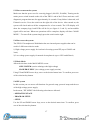
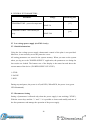
STEP OPERATIVE MODE
Each step can be programmed in 2 different mode:
STEP-AND-HOLD
During the execution of a protocol, when a STEP programmed in this mode
become active, the voltage applied to the strip is brought quickly to the value set in the
appropriate field and is maintained for the duration of the STEP.
GRADIENT
23
During the execution of a protocol, when a STEP programmed is this mode
become active, the voltage applied to the strip is carried gradually from the initial VOLT
value to the desired VOLT value set in the appropriate field.
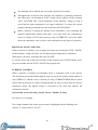
The system is designed to work with increase and decrease operative mode (figure 12, an
illustrative example).
VOLT
STEP 1
STEP 2
STEP 3
STEP 4
t
Figure 12
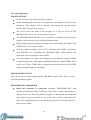
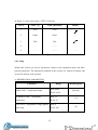
PROTOCOL END STEP
If a VOLT value is set to zero, all the parameters associated with the STEP and
subsequent periods are replaced by symbol "- -". This STEP is the first null-step of the
protocol and indicates the end of it.
In figure 13, the last step of the protocol is STEP 3
JUMP OF A STEP
If the value of TIME STEP is 00:00 , it means that that STEP will be skipped during the
protocol execution.
24
In Figure 13, at the end of step 1, STEP 3 will start
STEP
VOLT [V]
TIME [HH:MM]
MODE
1
5000
10:00
2
12000
00:00
3
7000
5:40
4
––
– –:– –
––
5
––
– –:– –
––
––
Figure 13
5.6.3 Setup
Within this section you can set parameters related to the rehydration phase and other
general parameters. The parameters modified in this section are written in memory and
are used in all next work sessions.
A. REHIDRATION PARAMETERS
Parameter
DURATION – rehydration lenght
Range
MIN: 00:00
MAX: 99:59
TEMPERATURE – rehydration
MIN: 15
temperature
MAX: 30
VOLTAGE – rehydration voltage applied
MIN: 0
to the strip
MAX: 100
25
Measuring unit
[hh:mm]
[°C]
[V]
B. GENERAL IEF PARAMETERS
Parameter
TEMPERATURE – protocol temperature
Range
Measuring unit
MIN: 15
[°C]
MAX: 30
CURRENT/STRIP – max current per
MIN: 10
strip
MAX: 200
[μA]
5.7 Low voltage power supply (for EWS-1 only)
5.7.1 Initial informations
Using the low voltage power supply, thermostatic control of the plate is not provided.
Moreover, is not necessary to use the protective cover.
All setting parameters are stored in the system memory. When you turn on the system
when you log on to the "POWER SUPPLY" application, the parameters set during the
last session are loaded. The bottom row of the display is the status bar and shows the
current status of the device ("POWER SUPPLY STATUS"):
1. STOP
2. PAUSE
3. RUN
During stop and pause, the power is off (red LED). When RUN, the power is on (green
LED illuminated).
5.7.2 Parameters Setting
Setting of parameters is allowed only when the power supply is not working ("STOP").
With the cursor keys and the "+" and "-" it is possible to choose and modify and one of
the four parameters and manage the operation of the power supply.
26
"MINIMUM CURRENT CONTROL": control over the minimum current output
"NO" → no control over the current minimum is made;
"YES" → a control is made on the minimum output current.
During protocol execution, if current results below the minimum threshold (see
next chapter on electrical characteristics and general), the power is turned off and
an error message will appear together with a warning acoustic sound.
"CONTROL TYPE": select the control mode. When this parameter is changed,
the value and measuring unit are updated automatically.
During system working is ever performed voltage control to the connectors and the load
current order to not exceed the max output values allowed by the system.
"VOLT" → voltage control is selected and active, the system acts on the value of
output
voltage, in order to ensure the voltage value set as a parameter.
"CURRENT" → current control is selected and active, the system acts on the
output voltage to achieve and maintain a current output equal to the desired value.
"POWER" → power control is selected and active, the system acts on the value of
output voltage and monitoring the load current, trying to achieve and ensure the
power value set as a parameter.
"VALUE SET": Based on the type of control chosen, you can set its parameter
number within the specified range (see the next chapter on electrical
characteristics and general).
"TIME": time management of the device. If time value is "00:00", there is no
countdown set. In this case all the operations must be stopped manually until the
user decides to interrupt the session by pressing "STOP" button. If the value time
is different than "00:00", all the operations will stop automatically once timer
finish the countdown and supply will turn off.
27
5.7.3 Start and pause
After setting the desired parameters, press "START" for a few seconds ("RUN" will
appear in the status bar). "REAL VALUES" table will indicate actual values of voltage,
current and power. It is possible to "PAUSE " the protocol at any time by pressing
"STOP button".
To resume, press "START ", the power is turned on again and system will re-start
working. If you used timer mode, you can always stop manually the operations.
28
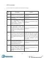
5.8 Error messages
In case of faulty errors an audible and visual alarm will appear.
Error
code
Description
Solution
Contact your local distributor or the
manufacturer.
01
EEPROM error: memory problem.
02
Temperature error:
system problem.
03
Error on the voltage value measured
by
high-voltage
module
Contact your local distributor or the
(IEFSYSTEM).
Without
any
manufacturer.
protocol running, is measured a
voltage different from zero.
04
Error on the voltage value measured
by high-voltage module (IEF
SYSTEM). During the execution of Contact your local distributor or the
a program, the voltage applied to manufacturer.
the strip is zero and cannot reach the
set value.
temperature Contact your local distributor or the
manufacturer.
05
Current Error on the IEF SYSTEM
module current. The current that
pass through the strip has exceeded
the maximum output allowed by the
device.
Turn off the device, wait some
seconds and then turn on again.
Check the following parameters:
current strip, voltage step, number of
strip set. Try to run again the
program. If the error recurs, contact
your local distributor or the
manufacturer.
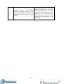
06
Error on low voltage module
(POWERSUPPLY). Without any
protocol running, is measured a
voltage different from zero.
Contact your local distributor or the
manufacturer.
07
Error on the voltage value measured
by low-voltage module (POWER
SUPPLY). During the execution of Contact your local distributor or the
a program, the voltage applied to manufacturer.
the strip is zero and cannot reach the
set value.
29
08
Current Error on the POWER
SUPPLY module current. The
current absorbed has exceeded the
maximum current allowed by the
device.
30
Turn off the device, wait some
seconds and then turn on again.
Check if any short-circuit are present
or check if the load has a very low
impedance. Try to reactivate the
power supply. If the error recurs,
contact your local distributor or the
manufacturer.
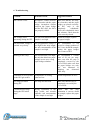
6. Troubleshooting
Problem
Probable reason
Suggested solution
The current is zero.
Incomplete contact between
the electrodes and the paper
bridge; incomplete contact
between the paper bridge
and the IPG strip; the lid is
not properly closed.
Make sure that the IPG strip,
the electrodes and the paper
bridges are placed correctly;
the IPG strip is not
completely
rehydrated:
check the rehydration times
and volumes; check that the
lid is correctly closed.
The voltage is not
increasing during the IEF.
The salt concentration of the
sample is too high.
Desalt the sample; replace
the paper bridges.
The maximum voltage is
reached very slowly.
The programmed voltage is
too high for the strip length;
the salt concentration of the
sample is too high.
We recommend to not
exceed a voltage gradient of
330 V/cm; desalt the sample;
replace the paper bridges
after 2 hours of IEF.
Burning of IPG strip.
The current limit is too high;
the strip has dried out; paper
bridges are too wet; wrong
paper bridge solutions.
We recommend a current
limit of 50 µA per strip;
make sure that the strip is
completely covered by the
Cover Fluid; make sure that
the paper bridges are only
wet, not saturated or
dripping; use deionized
water only.
Formation of urea crystals
on the IPG gel surface.
Temperature of cooling
plate too low.
Set the temperature at 20°C.
IPG strip turn white
during IEF.
The strip has dried out.
Make sure that the strip is
completely covered by the
Cover Fluid.
Current does not drop
during the IEF initial
stage.
Wrong orientation of the
strip (acidic end towards
cathode); salt concentration
of the sample is too high.
Check
that
the
strip
orientation is correct; desalt
the sample; replace the paper
bridges.
31
7. Recipes
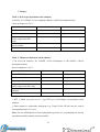
Table 1: IPG strip rehydration stock solution*
(8 M urea, 2% CHAPS, 0.5/2% Ampholyte Buffer, 0.002% bromophenol blue)
Store in aliquots at -20 °C.
Final concentration
Amount
Urea (FW 60.06)
8M
12 g
CHAPS‡
2% (w/v)
0.5 g
Ampholyte Buffer
(same range as the IPG
strip)
1% Bromophenol blue
stock solution
Double-distilled water
0.5% (v/v)
125 μl
0.002%
50 μl
—
to 25 ml
Table 2. Thiourea rehydration stock solution*
(7 M urea,2 M thiourea, 2% CHAPS, 0.5/2% Pharmalyte or IPG Buffer, 0.002%
bromophenol blue)
Store in aliquots at -20 °C.
Final concentration
Amount
Urea (FW 60.06)
7M
10.5 g
Thiourea (FW 76.12)
2M
3.8 g
CHAPS‡
2% (w/v)
0.5 g
Ampholyte Buffer
(same range as the IPG strip)
1% Bromophenol blue stock
solution
Double-distilled water
0.5% (v/v)
125 μl
0.002%
50 μl
—
to 25 ml
* DTT is added just prior to use: 7 mg DTT per 2.5-ml aliquot of rehydration stock
solution.
‡ Other neutral or zwitterionic detergents (e.g. Triton X-100, NP-40) may be used at
concentrations up to 2% (w/v).
Note: For the solubilization of more hydrophobic proteins it is recommended to use the
urea/thiourea buffer instead of the urea buffer.
32
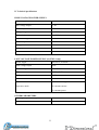
8. Technical specifications
HIGH VOLTAGE POWER SUPPLY
Power supply
100-250V, 50-60Hz
Max voltage output
15 KV
Power output
30 W
Voltage range
0 ÷ 15 KV
Current/strip range
10 ÷ 200 μA
Step timer range
00:00 ÷ 99:59 sec.
N. max strip
12
Volatge resolution
10 V
Storage protocols memory
10
Current resolution
1 μA
LOW VOLTAGE POWER SUPPLY (for EWS-1 only)
Power supplì
100-250V, 50-60Hz
Max voltage output
250V
Current range
10 ÷ 450mA
Timer
00:00 ÷ 99:59
Voltage resolution
10 V
Current resolution
1 mA
1) constant voltage
Operative mode
2) constant current
3) constant power
OTHER PARAMETERS
Working temperature range
10 ÷ 30 °C
Max humidity
< 90 % not condensing
33
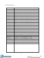
9. Ordering information
PRODUCT CODE DESCRIPTION
PRO-0012
EWS-1 Electrophoresis WorkStation
PRO-0010
P-Focus IEF system
PRO-0050
IEF strip tray (6 places)
PRO-0052
IEF strip tray (12 places)
PRO-0060
IEF equilibration tray for 8cm lenght strip – 14 places
PRO-0062
IEF equilibration tray for 24cm lenght strip – 6 places
PRO-0064
IEF equilibration tray for 45cm lenght strip – 6 places
PRO-0070
IEF rehydration tray for 8cm lenght strip – 14 places
PRO-0072
IEF rehydration tray for 24cm lenght strip – 6 places
PRO-0074
IEF rehydration tray for 45cm lenght strip – 6 places
PRO-0078
IEF Precut rectangular paper bridges (50pz)
PRO-0080
Cover Fluid
PRO-47712
IPG strip 4-7 / 7cm (1,5mm thickness) – 12 strips
PRO-471112
IPG strip 4-7 / 11cm (1,5mm thickness) – 12 strips
PRO-472412
IPG strip 4-7 / 24cm (1,5mm thickness) – 12 strips
PRO-310712
IPG strip 3-10 / 7cm (1,5mm thickness) – 12 strips
PRO-310NL712
IPG strip 3-10 NL / 7cm (1,5mm thickness) – 12 strips
PRO-610712
IPG strip 6-10 / 7cm (1,5mm thickness) – 12 strips
PRO-58712
IPG strip 5-8 / 7cm (1,5mm thickness) – 12 strips
PRO-36712
IPG strip 3-6 / 7cm (1,5mm thickness) – 12 strips
PRO-3101112
IPG strip 3-10 / 11cm (1,5mm thickness) – 12 strips
PRO-310NL1112
IPG strip 3-10 NL / 11cm (1,5mm thickness) – 12 strips
PRO-6101112
IPG strip 6-10 / 11cm (1,5mm thickness) – 12 strips
PRO-581112
IPG strip 5-8 / 11cm (1,5mm thickness) – 12 strips
PRO-361112
IPG strip 3-6 / 11cm (1,5mm thickness) – 12 strips
PRO-3102412
IPG strip 3-10 / 24cm (1,5mm thickness) – 12 strips
PRO-310NL2412
IPG strip 3-10 NL / 24cm (1,5mm thickness) – 12 strips
PRO-6102412
IPG strip 6-10 / 24cm (1,5mm thickness) – 12 strips
PRO-582412
IPG strip 5-8 / 24cm (1,5mm thickness) – 12 strips
PRO-362412
IPG strip 3-6 / 24cm (1,5mm thickness) – 12 strips
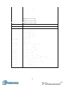
34
PRO-URE
Urea MB grade 500g
PRO-THI
Thiourea 99% 500g
PRO-AMB
Ampholyte Buffer
PRO-SER5810
SERVALYT™ 5-8; 10ml
PRO-SER5825
SERVALYT™ 5-8; 25ml
PRO-SER582
SERVALYT™ 5-8; 2ml
PRO-SER6910
SERVALYT™ 6-9; 10ml
PRO-SER6925
SERVALYT™ 6-9; 25ml
PRO-SER692
SERVALYT™ 6-9; 2ml
PRO-SER31010
SERVALYT™ 3-10; 10ml
PRO-SER31025
SERVALYT™ 3-10; 25ml
PRO-SER3102
SERVALYT™ 3-10; 2ml
PRO-SER4710
SERVALYT™ 4-7; 10ml
PRO-SER4725
SERVALYT™ 4-7; 25ml
PRO-SER472
SERVALYT™ 4-7; 2ml
PRO-CHP25
CHPAS 25 gr
PRO-CHP100
CHPAS 100 gr
PRO-DTT
DTT (dithiothreitol) MB grade 5g
PRO-IAA5
IAA (iodoacetamide) 5g
PRO-IAA25
IAA (iodoacetamide) 25g
PRO-TRX
Triton X-100 MB grade 250ml
PRO-TRI
Tris MB grade 1 Kg.
PRO-GLY
Glycine analytical grade 1 Kg.
PRO-SDS
SDS (sodium dodecylsulphate) MB grade 500g
PRO-MWM
Molecular Weight Markers Proteome markers 1 kit (5vials)
PRO-AGA
Agarose for DNA electrophoresis 500g
PRO-GLE
Glycerol MB grade 1L
PRO-BRB
Bromophenol Blue 25g
35
10. References
Cargile BJ, Bundy JL, Freeman TW, Stephenson JL Jr (2004). Gel based
isoelectric focusing of peptides and the utility of isoelectric point in protein
identification. J Proteome Res 3(1):112–119.
Cargile BJ, Sevinsky JR, Essader AS, Stephenson JL Jr, Bundy JL (2005).
Immobilized pH gradient isoelectric focusing as a first-dimension separation in
shotgun proteomics. J Biomol Tech 16 (3), 181-9.
Eriksson H, Lengqvist J, Hedlund J, Uhlen K, Orre LM, Bjellqvist B, Persson B,
Lehtio J, Jakobsson PJ (2008). Quantitative membrane proteomics applying
narrow range peptide isoelectric focusing for studies of small cell lung cancer
resistance mechanisms. Proteomics 8(15):3008–3018.
Fraterman S, Zeiger U, Khurana TS, Rubinstein NA, Wilm M (2007).
Combination of peptide OFFGEL fractionation and label-free quantitation
facilitated proteomics profiling of extraocular muscle. Proteomics 7(18):3404–
3416.
Geiser L, Vaezzadeh AR, Deshusses JM, Hochstrasser DF (2011). Shotgun
proteomics: a qualitative approach applying isoelectric focusing on immobilized
pH gradient and LC-MS/MS. Methods Mol Biol 681, 449-58.
Heller M, Michel PE, Morier P, Crettaz D, Wenz C, Tissot JD, Reymond F,
Rossier JS (2005). Two-stage Off-Gel isoelectric focusing: protein followed by
peptide fractionation and application to proteome analysis of human plasma.
Electrophoresis 26(6):1174–1188.
Millioni R, Miuzzo M, Puricelli L, Iori E, Sbrignadello S, Dosselli R, Cecconi D,
Tessari P, Righetti PG (2010). Improved instrumentation for large-size twodimensional protein maps. Electrophoresis 31(23-24):3863-6.
Poznanovic S, Schwall G, Zengerling H, Cahill MA (2005). Isoelectric focusing
in serial immobilized pH gradient gels to improve protein separation in proteomic
analysis. Electrophoresis 26(16):3185-90.
Xiao Z, Conrads TP, Lucas DA, Janini GM, Schaefer CF, Buetow KH, Issaq HJ,
Veenstra TD (2004). Direct ampholyte-free liquid-phase isoelectric peptide
focusing: application to the human serum proteome. Electrophoresis 25(1):12833.
36
37