1
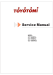
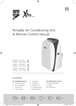
Service Manual
MODEL: DCT 35 INV-Si
DCT 50 INV-Si
DCT 70 INV-Si
DCT 100 INV-Si
DCT 140 INV-Si
DCT 170 INV-Si
TLC-I-2011.1
Part 1 General Information……………………………………………..……………………………1
Part 2 Indoor Units………………………………………………………………………………….
Part 3 Outdoor Units……………………………………………………………………………….
Part 5 Control……………………………………………………..…………………………….…
Part 6 Control Function…………………………………………..…………………………….…
Manufacture reserves the right to discontinue, or change at any time, specifications or designs without
notices and without incurring obligations.
i
TLC-I-2011.1
Part 1
General Information
1. Model Names of Indoor/Outdoor Units .......................... 2
2. External Appearance ....................................................... 4
3. Nomenclature ................................................................... 6
4. Features ............................................................................ 7
1
TLC-I-2011.1
1. Model Names of Indoor/Outdoor Units
1.1 Indoor Units
Model name
DCT 35 INV-Si
DCT 50 INV-Si
Dimension
(W×H×D) (mm)
920×210×635
920×210×635
Net/Gross weight (kg)
Power supply
25/29
220~240V-1ph-50Hz
26/30
220~240V-1ph-50Hz
DCT 70 INV-Si
920×270×635
30/34
220~240V-1ph-50Hz
DCT 90 INV-Si
1140×270×775
41/46
220~240V-1ph-50Hz
DCT 100 INV-Si
1140×270×775
41/46
220~240V-1ph-50Hz
DCT 140 INV-Si
1200×300×865
49/55
220~240V-1ph-50Hz
DCT 170 INV-Si
1200×300×865
49/55
220~240V-1ph-50Hz
CFT 35 INV-Ri
990×203×660
27/33
220~240V-1ph-50Hz
CFT 50 INV-Ri
990×203×660
29/35
220~240V-1ph-50Hz
CFT 70 INV-Ri
990×203×660
29/35
220~240V-1ph-50Hz
CFT 90 INV-Ri
1280 ×203× 660
37/42
220~240V-1ph-50Hz
CFT 100 INV-Ri
1280 ×203× 660
37/42
220~240V-1ph-50Hz
CFT 140 INV-Ri
1670× 240× 680
52/59
220~240V-1ph-50Hz
CFT 170 INV-Ri
1670× 240× 680
52/59
220~240V-1ph-50Hz
CCT 50 INV-Si
CCT 70 INV-Si
840x230x840
28/34
220~240V-1ph-50Hz
840x230x840
29/36
220~240V-1ph-50Hz
CCT 90 INV-Si
840x300x840
36/41
220~240V-1ph-50Hz
CCT 100 INV-Si
840x300x840
36/41
220~240V-1ph-50Hz
CCT 140 INV-Si
840x300x840
36/41
220~240V-1ph-50Hz
CCT 170 INV-Si
840x300x840
42/50
220~240V-1ph-50Hz
CCT 301 INVi
580x254x580
18/27.5
220~240V-1ph-50Hz
CCT 501 INVi
580x254x580
21/28
220~240V-1ph-50Hz
1.2 Outdoor Units
Model name
CCT 301 INVo
CFT 35 INV-Ro
DCT 35 INV-So
CCT 501 INVo
CCT 50 INV-So
CFT 50 INV-Ro
DCT 50 INV-So
CCT 70 INV-So
CFT 70 INV-Ro
DCT 70 INV-So
CCT 100 INV-So-1
CFT 100 INV-Ro-1
DCT 100 INV-So-1
CCT 90 INV-So
CFT 90 INV-Ro
DCT 90 INV-So
CCT 100 INV-So
CFT 100 INV-Ro
DCT 100 INV-So
CCT 140 INV-So-1
CFT 140 INV-Ro-1
DCT 140 INV-So-1
2
Dimension
(W×H×D) (mm)
Net/Gross weight
(kg)
Power supply
761×593×279
39.5/42.5
220~240V-1ph-50Hz
842×695×324
59/63
220~240V-1ph-50Hz
895x862x313
73/76
220~240V-1 Ph-50Hz
940×1245×360
106/114
220~240V-1ph-50Hz
990×966×354
92/100
220~240V-1ph-50Hz
990×966×354
87/95
380V-3ph-50Hz
940×1245×360
106/114
220~240V-1ph-50Hz
TLC-I-2011.1
CCT 140 INV-So
CFT 140 INV-Ro
DCT 140 INV-So
CCT 170 INV-So
CFT 170 INV-Ro
DCT 170 INV-So
DHP 170 INV -Ro
940×1245×360
99/107
380V-3ph-50Hz
940×1245×360
115/121
380V-3ph-50Hz
940×1245×360
124/130
380~415V-3 Ph-50Hz
3
TLC-I-2011.1
2. External Appearance
2.1 Indoor units
Duct
4
TLC-I-2011.1
2.2 Outdoor unit
CCT 301 INVo, CFT 35 INV-Ro, DCT 35 INV-So
CCT 70 INV-So, CFT 70 INV-Ro, DCT 70 INV-So
CCT 501 INVo, CCT 50 INV-So,
CFT 50 INV-Ro, DCT 50 INV-So
CCT 90 INV-So, CFT 90 INV-Ro, DCT 90 INV-So
CCT 100 INV-So, CFT 100 INV-Ro, DCT 100 INV-So
CCT 100 INV-So-1, CFT 100 INV-Ro-1, DCT 100 INV-So-1
CCT 140 INV-So-1, CFT 140 INV-Ro-1, DCT 140 INV-So-1
CCT 140 INV-So, CFT 140 INV-Ro, DCT 140 INV-So
CCT 170 INV-So, CFT 170 INV-Ro, DCT 170 INV-So
DHP 170 INV -Ro
5
TLC-I-2011.1
3. Nomenclature
6
TLC-I-2011.1
4. Features
4.1 Universal outdoor unit design
Indoor unit with the same capacity can match with the same outdoor unit.
4.2 High efficiency and energy saving.
Thanks to the DC inverter technology and optimized piping system, the EER and COP of whole
series can easily reach A-class.
4.3 Low noise and low starting current.
Thanks to the DC inverter technology, the system can work with low noise, and very small starting
current.
4.4 Intelligent refrigerant adjustment technology.
Throttle part is made up of capillary and electronic expansion valve (EXV). The outdoor unit can
output the most accurate capacity in any condition.
4.5 Working in cooling mode under -15 .
Outdoor unit built-in with low ambient kit, it can control the outdoor unit’s fan and cooling can be
performed throughout the year for computer rooms, banquet halls, etc. Wide operation range
covers outdoor temperatures as low as -15 for cooling.
4.6 Indoor & outdoor unit’s power supply is separate.
4.7 All indoor units have network control function.
4.8 All indoor units have Auto-restart function.
7
TLC-I-2011.1
Part 2
Indoor Units
1. Duct Type…………………………………………………
8
TLC-I-2011.1
Duct Type
1. Features ...................................................................................................
2. Specifications ..........................................................................................
3. Dimensions (Unit: mm) ...........................................................................
4. Service Space ..........................................................................................
5. Wiring Diagrams ......................................................................................
6. Air Velocity and Temperature Distributions ..........................................
7. Capacity Tables .......................................................................................
8. Electric Characteristics ..........................................................................
9. Sound Levels ...........................................................................................
Accessories ...........................................................................................
41
TLC-I-2011.1
1. Features
● New structure design.
● Built-in drain pump.
● Two air intake ways: from below or rear (standard).
● Wired controller is standard.
● Four speeds indoor unit.
● Fresh air inlet hole is reserved.
● Standard aluminum alloy filter, which is more convenient to replace.
42
TLC-I-2011.1
2. Specifications
Capacity(Max.-Rated-Min.)
Model
name
Code
Power
supply
Model
name
Code
Power
supply
kW
Input(Max.-Rated-Min.)
kW
Current(Max.-Rated-Min.)
A
6.46-4.79-2.15
3.27
3.25
Capacity(Max.-Rated-Min.)
kW
4.54-3.81-1.51
7.19-5.86-2.40
Input(Max.-Rated-Min.)
kW
1.46-1.03-0.49
2.33-1.60-0.78
Current(Max.-Rated-Min.)
A
6.70-5.58-2.23
10.64-8.87-3.55
3.7
3.66
Indoor
Model
Outdoor
Cooling
EER
Heating
COP
DCT 35 INV-Si
DCT 50 INV-Si
220070100120
220070201170
220~240V-1 Ph-50Hz
220~240V-1 Ph-50Hz
DCT 35 INV-So
DCT 50 INV-So
220075100071
220075200340
220~240V-1 Ph-50Hz
220~240V-1 Ph-50Hz
3.84 -3.52 -1.40
6.36 -5.28-2.12
1.42 -1.075-0.47
2.28 -1.62-0.76
10.41-7.46-2.52
Max. input consumption
W
2250
2400
Max. current
A
12
13.1
Compressor
Model
DA108X1C-20FZ3
C-6RVN93H0V
Type
Rotary DC Inverter
Rotary DC Inverter
Brand
Midea-Toshiba
SANYO(Shen yang)
10918.4
19278
Capacity
Btu/h
Input
W
855
1470
Rated current(RLA)
A
5.3
8.96
_
_
Thermal protector
Indoor fan
motor
Capacitor
uF
_
_
Refrigerant oil
ml
ESTER OIL VG74, 480
FV 50S, 350
Model
YSK25-4P
YSK68-4P
Type
AC Motor
AC Motor
Input
W
62
107
Capacitor
uF
2uF/450V
3.5uF/450V
Speed(hi/mi/lo)
r/min
830/720/660/580
1150/1020/800/700
2
3
a.Number of rows
Indoor coil
b.Tube pitch(a)x row pitch(b)
mm
21×13.37
21×13.37
c.Fin spacing
mm
1.5
1.5
e.Tube outside dia.and type
mm
f.Coil length× height×width
mm
Hydrophilic aluminum
Ф7 Inner grooved copper
tube
735×252×26.74
Hydrophilic aluminum
Ф7 Inner grooved copper
tube
735×252×40.11
3
4
913/782/702
1205/1000/945
30
30
d.Fin type (code)
g.Number of circuits
3
Indoor air flow (Hi/Mi/Lo) (0 Pa)
m /h
Indoor external static pressure (Hi)
Pa
Sound level (sound pressure)
dB(A)
36.9 /30.2/26.4
44.0/35.9/32.8
Dimension (W×H×D)
mm
920×210×635
920×210×635
Indoor unit
Packing (W×H×D)
mm
1100×270×695
1100×270×695
Net/Gross weight
Kg
25/29
26/30
Outdoor fan
motor
Model
YDK24-6G (×1)
YDK53-6Y (×1)
Type
AC Motor
AC Motor
43
TLC-I-2011.1
Input
W
67/48
129/86
Capacitor
uF
2.5uF/450V
3uF/450V
Speed
r/min
800/550
770/560
2
2
Number of rows
Outdoor coil
Tube pitch(a)× row pitch(b)
mm
25.4×22
22×19.05
Fin spacing
mm
1.4
1.4
Tube outside dia.and type
mm
Coil length×height×width
mm
Hydrophilic aluminum
Ф9.53 Inner grooved
copper tube
654×558.8×44
Hydrophilic aluminum
Ф7.94 Inner grooved
copper tube
778×660×38.1
2
2
Fin type (code)
Number of circuits
3
Outdoor air flow(Hi/Low)
m /h
2500/1600
2570/2300
Sound level(sound pressure)(Hi/Low)
dB(A)
48/44
51/46
Outdoor unit
Refrigerant
Dimension (W×H×D)
mm
761×593×279
842×695×324
Packing (W×H×D)
mm
887×655×355
965x752x399
Net/Gross weight
kg
39.5/42.5
59/63
R410A
R410A
1400
Type
Charged volume
g
MPa
4.2/2.0
1600
Electronic expansion valve &
Capillary
4.2/2.0
Liquid side/ Gas side
mm
6.4/12.7
6.4/12.7
Max. refrigerant pipe length
Max. difference in level(Outdoor is
up)
Max. difference in level (Outdoor
is down)
Power wiring (Indoor)
m
10
25
m
6
12
Throttle type
Capillary
Design pressure(Hi/Low)
Refrigerant
piping
Connection
wiring
Power wiring (Outdoor)
Signal wiring
Drainage water pipe dia. (Indoor)
Wired controller (Indoor) (standard)
m
5
9
mm
2
3×1.5
3×1.0
mm
2
_
3×2.5
mm
2
4×1.5
mm
3-core shield wire
Ф25
Ф25
3×0.5
KJR-10B/DP(T)-E
KJR-10B/DP(T)-E
Operation temp. (Indoor)
17-30
17-30
Ambient temp. (Outdoor)
Cooling 0~43(*)
Heating -15~24
Cooling -15~43(*)
Heating -15~24
o
(*) Optional Low Ambient Kit included. Cooling operation range without it: 7 to 43 C
44
TLC-I-2011.1
Capacity(Max.-Rated-Min.)
Model
name
Code
Power
supply
Model
name
Code
Power
supply
kW
Input(Max.-Rated-Min.)
kW
Current(Max.-Rated-Min.)
A
Indoor
Model
Outdoor
Cooling
EER
Heating
DCT 70 INV-Si
DCT 90 INV-Si
220070301180
220070401060
220~240V-1 Ph-50Hz
220~240V-1 Ph-50Hz
DCT 70 INV-So
DCT 90 INV-So
220075301070
220075401041
220~240V-1 Ph-50Hz
220~240V-1 Ph-50Hz
8.36- 7.03-2.79
10.81- 9.00-3.61
3.01-2.17-1.00
3.98-2.79- 1.33
13.76-10.02-4.59
18.22-12.77-6.07
3.24
3.23
Capacity(Max.-Rated-Min.)
kW
9.64-7.62-3.21
12.16-9.50-4.05
Input(Max.-Rated-Min.)
kW
3.13-2.09-1.04
3.92-2.62-1.31
Current(Max.-Rated-Min.)
A
14.34-11.95-4.78
17.94-14.95-5.98
3.64
3.63
COP
Max. input consumption
W
3250
4600
Max. current
A
15.48
23
Compressor
Model
ATL165SD-C9AU
TNB220FLBM1
Type
Rotary DC Inverter
Rotary DC Inverter
Brand
HITACHI(Shang hai)
MITSUBISHI ELECTRIC
Capacity
Btu/h
15525
24328
Input
W
1530
2200
Rated current(RLA)
A
10.4
9.7
_
_
Thermal protector
Indoor fan
motor
Capacitor
uF
_
_
Refrigerant oil
ml
68HES-H, 880
MEL 56, 670
Model
YSK74-4P
YSK100-4P
Type
AC Motor
AC Motor
Input
W
163
227
Capacitor
uF
3.5uF/450V
10uF±5% 450V
Speed(hi/mi/lo)
r/min
1000/850/750/670
935/810/700/620
4
4
a.Number of rows
Indoor coil
b.Tube pitch(a)x row pitch(b)
mm
21×13.37
21×13.37
c.Fin spacing
mm
1.5
1.5
e.Tube outside dia.and type
mm
f.Coil length× height×width
mm
Hydrophilic aluminum
Ф7 Inner grooved copper
tube
735×252×53.48
Hydrophilic aluminum
Ф7 Inner grooved copper
tube
955×336×53.48
6
8
1800/1500/1200
2200/1918/1800
30
50
d.Fin type (code)
g.Number of circuits
3
Indoor air flow (Hi/Mi/Lo) (0 Pa)
m /h
Indoor external static pressure (Hi)
Pa
Sound level (sound pressure)
dB(A)
45.1/43.2/40.9
46.1/44.0/42.2
Dimension (W×H×D)
mm
920×270×635
1140×270×775
Indoor unit
Packing (W×H×D)
mm
1100×330×695
1320×310×835
Net/Gross weight
Kg
30/34
41/46
Outdoor fan
motor
Model
YDK53-6Z (×1)
YDK250-6E (×1)
Type
AC Motor
AC Motor
45
TLC-I-2011.1
Input
W
141.5/92
307/194
Capacitor
uF
3uF/450V
10uF±5% 450V
Speed
r/min
815/550
740/530
2
2
Number of rows
Outdoor coil
Tube pitch(a)× row pitch(b)
mm
25.4×22
25.4×22
Fin spacing
mm
1.5
1.7
Tube outside dia.and type
mm
Coil length×height×width
mm
Hydrophilic aluminum
Ф9.53 Inner grooved
copper tube
758x813x44
Hydrophilic aluminum
Ф9.53 Inner grooved
copper tube
876x914.4x44
2
4
Fin type (code)
Number of circuits
3
Outdoor air flow(Hi/Low)
m /h
3200/2850
5000/4800
Sound level(sound pressure)(Hi/Low)
dB(A)
53/48
55/50
Outdoor unit
Refrigerant
Dimension (W×H×D)
mm
895×862×313
990×966×354
Packing (W×H×D)
mm
1043×915×395
1120×1100×435
Net/Gross weight
kg
73/76
92/100
R410A
R410A
2300
Type
Charged volume
g
MPa
4.2/2.0
3350
Electronic expansion valve
& Capillary
4.2/2.0
Liquid side/ Gas side
mm
9.5/15.9
9.5/15.9
Max. refrigerant pipe length
Max. difference in level(Outdoor is
up)
Max. difference in level (Outdoor
is down)
Power wiring (Indoor)
m
25
25
m
12
15
Throttle type
Electronic expansion valve
Design pressure(Hi/Low)
Refrigerant
piping
Connection
wiring
Power wiring (Outdoor)
Signal wiring
Drainage water pipe dia. (Indoor)
Wired controller (Indoor) (standard)
m
9
9
mm
2
3×1.0
3×1.0
mm
2
3×2.5
3×2.5
mm
2
mm
3-core shield wire
3×0.5
3-core shield wire
Ф25
Ф25
3×0.5
KJR-10B/DP(T)-E
KJR-10B/DP(T)-E
Operation temp. (Indoor)
17-30
17-30
Ambient temp. (Outdoor)
Cooling -15~43(*)
Heating -15~24
Cooling -15~43(*)
Heating -15~24
o
(*) Optional Low Ambient Kit included. Cooling operation range without it: 7 to 43 C
46
TLC-I-2011.1
Capacity(Max.-Rated-Min.)
Model
name
Code
Power
supply
Model
name
Code
Power
supply
kW
Input(Max.-Rated-Min.)
kW
Current(Max.-Rated-Min.)
A
Indoor
Model
Outdoor
Cooling
EER
DCT 100 INV-Si-1
DCT 100 INV-Si
220070501330
220070501330
220~240V-1 Ph-50Hz
220~240V-1 Ph-50Hz
DCT 100 INV-So-1
DCT 100 INV-So
220075500651
220075500920
220~240V-1 Ph-50Hz
380V~3 Ph-50Hz
12.60-10.5-4.20
12.34-10.55-4.12
4.42-3.26-1.47
4.39-3.26-1.45
20.23-14.92-6.74
6.72-4.79-2.10
3.22
3.23
Capacity(Max.-Rated-Min.)
kW
15.06-12.00-5.02
15.06-11.72-5.02
Input(Max.-Rated-Min.)
kW
4.87-3.31-1.62
4.87-3.23-1.62
Current(Max.-Rated-Min.)
A
22.31-18.59-7.44
7.46-4.88-2.35
3.63
3.63
Max. input consumption
W
5500
5000
Max. current
A
25
7.5
Model
TNB306FPGM
TNB306FPNM
Type
Rotary DC Inverter
Rotary DC Inverter
Brand
MITSUBISHI ELECTRIC
MITSUBISHI ELECTRIC
Btu/h
33642
33710
Input
W
3080
3010
Rated current(RLA)
A
13.5
9.3
-
-
Heating
COP
Capacity
Compressor
Thermal protector
Indoor fan
motor
Capacitor
uF
-
-
Refrigerant oil
ml
FV50S, 870
FV50S, 870
Model
YSK140-4P
YSK140-4P
Type
AC Motor
AC Motor
291
291
Input
W
Capacitor
uF
Speed(hi/mi/lo)
r/min
a.Number of rows
Indoor coil
4
4
mm
21×13.37
21×13.37
c.Fin spacing
mm
1.5
1.5
e.Tube outside dia.and type
mm
f.Coil length× height×width
mm
Hydrophilic aluminum
Ф7 Inner grooved copper
tube
955×336×53.48
Hydrophilic aluminum
Ф7 Inner grooved copper
tube
955×336×53.48
8
8
2200/1920/1800
2200/1920/1800
80
80
d.Fin type (code)
3
Indoor air flow (Hi/Mi/Lo) (0 Pa)
m /h
Indoor external static pressure (Hi)
Pa
Sound level (sound pressure)
Outdoor fan
motor
10uF±5% 450V
1070/960/790/710
b.Tube pitch(a)x row pitch(b)
g.Number of circuits
Indoor unit
10uF±5% 450V
1070/960/790/710
dB(A)
46.1/44.0/42.2
46.1/44.0/42.2
Dimension (W×H×D)
mm
1140×270×775
1140×270×775
Packing (W×H×D)
mm
1320×310×835
1320×310×835
Net/Gross weight
Kg
41/46
41/46
Model
YDK100-6A(×2)
YDK250-6E(×1)
Type
AC Motor
AC Motor
185/120
307/194
Input
W
47
TLC-I-2011.1
Capacitor
uF
Speed
r/min
Number of rows
Outdoor coil
2
2
25.4×22
Fin spacing
mm
1.5
1.7
Tube outside dia.and type
mm
Coil length×height×width
mm
Hydrophilic aluminum
Ф9.53 Inner grooved
copper tube
887×1220×44
Hydrophilic aluminum
Ф9.53 Inner grooved
copper tube
876×914.4×44
8
4
6000/5800
5000/4800
Fin type (code)
3
Sound level(sound pressure)(Hi/Low)
dB(A)
57/52
55/50
Dimension (W×H×D)
mm
940×1245×360
990×966×354
Packing (W×H×D)
mm
1058×1380×438
1120×1100×435
Net/Gross weight
kg
106/114
87/95
R410A
R410A
MPa
4100
Electronic expansion valve
& Capillary
4.2/2.0
2900
Electronic expansion valve
& Capillary
4.2/2.0
Liquid side/ Gas side
mm
9.5/15.9
9.5/15.9
Max. refrigerant pipe length
Max. difference in level(Outdoor
is up)
Max. difference in level (Outdoor
is down)
Power wiring (Indoor)
m
30
30
m
20
20
Type
Charged volume
g
Throttle type
Design pressure(Hi/Low)
Connection
wiring
740/530
25.4×22
m /h
Refrigerant
piping
860/610
mm
Outdoor air flow(Hi/Low)
Refrigerant
10uF±5% 450V
Tube pitch(a)× row pitch(b)
Number of circuits
Outdoor unit
3.5uF/450V
Power wiring (Outdoor)
Signal wiring
Drainage water pipe dia. (Indoor)
Wired controller (Indoor) (standard)
m
12
12
mm
2
3×1.0
3×1.0
mm
2
3×2.5
5×2.5
mm
2
mm
3-core shield wire
3×0.5
3-core shield wire
3×0.5
Ф25
Ф25
KJR-10B/DP(T)-E
KJR-10B/DP(T)-E
Operation temp. (Indoor)
17-30
17-30
Ambient temp. (Outdoor)
Cooling -15~43(*)
Heating -15~24
Cooling -15~43(*)
Heating -15~24
o
(*) Optional Low Ambient Kit included. Cooling operation range without it: 7 to 43 C
48
TLC-I-2011.1
Capacity(Max.-Rated-Min.)
Model
name
Code
Power
supply
Model
name
Code
Power
supply
kW
Input(Max.-Rated-Min.)
kW
5.44-4.35-1.81
5.53-4.36-1.84
6.22-5.47-2.07
Current(Max.-Rated-Min.)
A
24.90-19.91-8.3
7.9-6.30-2.65
9.54-7.68-2.97
3.22
3.22
3.21
Capacity(Max.-Rated-Min.)
kW
17.04-15.00-5.68
17.58-15.24-5.86
20.48-20.22-6.72
Input(Max.-Rated-Min.)
kW
5.53-4.16-1.84
5.71-4.22-1.90
6.59-5.67-2.20
Current(Max.-Rated-Min.)
A
25.32-21.1-8.44
8.15-6.03-2.72
10.1-8.03-3.15
3.61
3.61
3.61
Indoor
Model
Outdoor
Cooling
EER
Heating
COP
DCT 140 INV-Si
DCT 140 INV-Si
DCT 170 INV-Si
220070701290
220~240V-1
Ph-50Hz
220070701290
220~240V-1
Ph-50Hz
220070801420
220~240V-1
Ph-50Hz
DCT 140 INV-So-1
DCT 140 INV-So
DCT 170 INV-So
220075700341
220~240V-1
Ph-50Hz
14.86 -14.00-4.95
220075700690
220075800161
380V~3 Ph-50Hz
380V~3 Ph-50Hz
15.14-14.06-5.05
17.96-17.58-4.21
Max. input consumption
W
6000
5500
7500
Max. current
A
28
7.8
11.5
Model
TNB306FPGM
TNB306FPNM
ANB42FBEMT
Type
Rotary DC Inverter
MITSUBISHI
ELECTRIC
33642
Rotary DC Inverter
MITSUBISHI
ELECTRIC
33710
Scroll DC Inverter
Brand
Compressor
Capacity
Btu/h
Input
W
3080
3010
4160
Rated current(RLA)
A
13.5
9.3
15.2
-
-
-
Thermal protector
Indoor fan
motor
47440
Capacitor
uF
-
-
-
Refrigerant oil
ml
FV50S, 870
FV50S, 870
MEL 56, 1700
Model
YSK170-4P
YSK170-4P
YSK180-4P
Type
AC Motor
AC Motor
AC Motor
Input
W
356
356
355
Capacitor
uF
10uF±5% 450V
10uF±5% 450V
10uF±5% 450V
Speed(hi/mi/lo)
r/min
1070/900/750/650
1070/900/750/650
1080/960/830/710
4
4
4
a.Number of rows
Indoor coil
SIAM
b.Tube pitch(a)x row pitch(b)
mm
21×13.37
21×13.37
21×13.37
c.Fin spacing
mm
1.5
Hydrophilic
aluminum
Ф7 Inner grooved
copper tube
1030×378×53.48
1.5
Hydrophilic
aluminum
Ф7 Inner grooved
copper tube
1030×378×53.48
1.5
Hydrophilic
aluminum
Ф7 Inner grooved
copper tube
1030×378×53.48
8
8
8
2812/2458/2090
2812/2458/2090
2890/2465/2138
100
100
100
d.Fin type (code)
e.Tube outside dia.and type
mm
f.Coil length× height×width
mm
g.Number of circuits
3
Indoor air flow (Hi/Mi/Lo) (0 Pa)
m /h
Indoor external static pressure (Hi)
Pa
Sound level (sound pressure)
dB(A)
47.1/45.3/42.9
47.1/45.3/42.9
47.3/45.2/43.1
mm
1200×300×865
1200×300×865
1200×300×865
Packing (W×H×D)
mm
1405×365×935
1405×365×935
1405×365×935
Net/Gross weight
Kg
49/55
49/55
49/55
Model
YDK100-6A(×2)
YDK100-6A(×2)
YDK100-6A(×2)
Type
AC Motor
AC Motor
AC Motor
Dimension (W×H×D)
Indoor unit
Outdoor fan
motor
49
TLC-I-2011.1
Input
W
185/120
185/120
185/120
Capacitor
uF
3.5uF/450V
3.5uF/450V
3.5uF/450V
Speed
r/min
860/610
860/610
860/610
2
2
2
Number of rows
Outdoor coil
Tube pitch(a)× row pitch(b)
mm
25.4×22
25.4×22
25.4×22
Fin spacing
mm
1.5
Hydrophilic
aluminum
Ф9.53 Inner
grooved copper
tube
887×1220×44
1.8
Hydrophilic
aluminum
Ф9.53 Inner
grooved copper
tube
887×1220×44
1.8
Hydrophilic
aluminum
Ф9.53 Inner
grooved copper
tube
887×1220×44
8
8
4
Fin type (code)
Tube outside dia.and type
mm
Coil length×height×width
mm
Number of circuits
3
Outdoor air flow(Hi/Low)
m /h
6000/5800
6000/5800
6000/5800
Sound level(sound pressure)(Hi/Low)
dB(A)
59/54
59/54
59/54
Outdoor unit
Refrigerant
Dimension (W×H×D)
mm
940×1245×360
940×1245×360
940×1245×360
Packing (W×H×D)
mm
1058×1380×438
1058×1380×438
1058×1380×438
Net/Gross weight
kg
106/114
99/107
115/121
R410A
R410A
R410A
3600
Electronic expansion
valve & Capillary
MPa
4450
Electronic
expansion valve &
Capillary
4.2/2.0
4.2/2.0
3850
Electronic
expansion valve &
Capillary
4.2/2.0
Liquid side/ Gas side
mm
9.5/15.9
9.5/15.9
9.5/15.9
Max. refrigerant pipe length
Max. difference in
level(Outdoor is up)
Max. difference in level
(Outdoor is down)
Power wiring (Indoor)
m
50
50
50
m
25
30
30
m
20
20
20
Type
Charged volume
g
Throttle type
Design pressure(Hi/Low)
Refrigerant
piping
Connection
wiring
Power wiring (Outdoor)
Signal wiring
Drainage water pipe dia. (Indoor)
Wired controller (Indoor) (standard)
mm
2
3×1.0
3×1.0
3×1.0
mm
2
mm
2
3×2.5
3-core shield wire
3×0.5
Ф25
5×2.5
3-core shield wire
3×0.5
Ф25
5×2.5
3-core shield wire
3×0.5
Ф25
mm
KJR-10B/DP(T)-E
KJR-10B/DP(T)-E
KJR-10B/DP(T)-E
Operation temp. (Indoor)
17-30
17-30
17-30
Ambient temp. (Outdoor)
Cooling -15~43(*)
Heating -15~24
Cooling -15~43(*)
Heating -15~24
Cooling -15~43(*)
Heating -15~24
o
(*) Optional Low Ambient Kit included. Cooling operation range without it: 7 to 43 C
50
TLC-I-2011.1
3. Dimensions (Unit: mm)
Outline dimension and air outlet size
Air return size
Outline dimension
12~18
Air outlet size
Air return size
Size of mounted lug
A
B
C
D
E
F
G
H
I
J
K
L
M
920
210
635
570
65
713
35
119
815
200
80
960
350
24
920
270
635
570
65
713
35
179
815
260
20
960
350
30~36
1140
270
775
710
65
933
35
179
1035
260
20
1180
490
48~60
1200
300
865
800
80
968
40
204
1094
288
45
1240
500
51
TLC-I-2011.1
4. Service Space
52
TLC-I-2011.1
5. Wiring Diagrams
DCT 35 INV-Si
53
TLC-I-2011.1
DCT 50 INV-Si
DCT 100 INV-Si
54
DCT 70 INV-Si
DCT 140 INV-Si
DCT 90 INV-Si
DCT 170 INV-Si
TLC-I-2011.1
6. Air Velocity and Temperature Distributions
55
TLC-I-2011.1
7. Capacity Tables
DCT 35 INV-Si
Cooling
Indoor temperature(°C WB)
Outdoor
temperature(°C
DB)
14.00
16.00
18.00
19.00
20.00
22.00
24.00
TC
PI
TC
PI
TC
PI
TC
PI
TC
PI
TC
PI
TC
PI
kW
kW
kW
kW
kW
kW
kW
kW
kW
kW
kW
kW
kW
kW
10.00
2.22
0.33
2.72
0.41
3.22
0.49
3.52
0.53
3.68
0.58
3.76
0.58
3.83
0.58
12.00
2.22
0.34
2.72
0.42
3.22
0.50
3.52
0.54
3.68
0.59
3.76
0.59
3.83
0.59
14.00
2.22
0.34
2.72
0.43
3.22
0.51
3.52
0.55
3.68
0.60
3.76
0.60
3.83
0.61
16.00
2.22
0.35
2.72
0.43
3.22
0.52
3.52
0.56
3.68
0.61
3.76
0.61
3.83
0.62
18.00
2.22
0.35
2.72
0.44
3.22
0.53
3.52
0.57
3.68
0.62
3.76
0.62
3.83
0.63
19.00
2.22
0.36
2.72
0.45
3.22
0.54
3.52
0.58
3.68
0.63
3.76
0.63
3.83
0.64
21.00
2.22
0.39
2.72
0.48
3.22
0.58
3.52
0.63
3.68
0.68
3.76
0.68
3.83
0.68
23.00
2.22
0.41
2.72
0.52
3.22
0.62
3.52
0.67
3.68
0.72
3.76
0.73
3.83
0.73
25.00
2.22
0.44
2.72
0.55
3.22
0.66
3.52
0.72
3.68
0.77
3.76
0.78
3.83
0.78
27.00
2.22
0.47
2.72
0.59
3.22
0.71
3.52
0.77
3.68
0.83
3.76
0.83
3.83
0.84
29.00
2.22
0.51
2.72
0.63
3.22
0.76
3.52
0.82
3.68
0.88
3.76
0.89
3.83
0.89
31.00
2.22
0.54
2.72
0.67
3.22
0.81
3.52
0.87
3.68
0.94
3.76
0.94
3.83
0.95
33.00
2.22
0.58
2.72
0.72
3.22
0.86
3.52
0.97
3.68
1.00
3.76
1.01
3.83
1.02
35.00
2.22
0.61
2.72
0.76
3.22
0.91
3.52
1.09
3.68
1.07
3.76
1.07
3.83
1.08
37.00
2.22
0.65
2.72
0.81
3.22
0.97
3.52
1.11
3.68
1.14
3.76
1.14
3.83
1.15
39.00
2.22
0.65
2.72
0.81
3.22
0.98
3.52
1.13
3.68
1.14
3.76
1.14
3.83
1.15
41.00
2.22
0.66
2.72
0.82
3.22
0.98
3.52
1.14
3.68
1.15
3.76
1.15
3.83
1.16
43.00
2.22
0.66
2.72
0.82
3.22
0.98
3.52
1.14
3.68
1.15
3.76
1.15
3.83
1.17
Heating
Indoor temperature(°C DB)
Outdoor air temp.
16
18
20
21
22
24
TC
PI
TC
PI
TC
PI
TC
PI
TC
PI
TC
PI
°C DB
°C WB
kW
kW
kW
kW
kW
kW
kW
kW
kW
kW
kW
kW
-14.7
-15
2.54
0.88
2.54
0.90
2.54
0.92
2.44
0.88
2.34
0.84
2.14
0.76
-12.6
-13
2.68
0.90
2.68
0.92
2.68
0.94
2.57
0.90
2.47
0.86
2.26
0.77
-10.5
-11
2.82
0.91
2.82
0.93
2.82
0.95
2.71
0.91
2.60
0.87
2.37
0.79
-9.5
-10
2.89
0.92
2.89
0.94
2.89
0.96
2.77
0.92
2.66
0.88
2.43
0.79
-8.5
-9.1
2.96
0.93
2.96
0.95
2.96
0.97
2.84
0.93
2.72
0.88
2.49
0.80
-7
-7.6
3.06
0.94
3.06
0.96
3.06
0.98
2.94
0.94
2.82
0.89
2.57
0.81
-5
-5.6
3.19
0.95
3.19
0.97
3.19
1.00
3.07
0.95
2.94
0.91
2.69
0.82
-3
-3.7
3.33
0.97
3.33
0.99
3.33
1.01
3.20
0.96
3.06
0.92
2.80
0.83
0
-0.7
3.53
0.99
3.53
1.01
3.53
1.00
3.39
0.98
3.25
0.94
2.97
0.85
3
2.2
3.73
1.03
3.73
1.03
3.73
1.01
3.58
1.00
3.43
0.96
3.14
0.87
5
4.1
3.87
1.02
3.87
1.02
3.87
1.02
3.71
1.02
3.56
0.97
3.25
0.88
7
6
3.81
1.01
3.81
1.01
3.81
1.03
3.84
1.03
3.68
0.99
3.37
0.89
9
7.9
3.81
1.00
3.81
1.01
3.81
1.02
3.84
1.00
3.68
0.95
3.37
0.86
11
9.8
3.81
0.97
3.81
0.99
3.81
1.01
3.84
0.96
3.68
0.92
3.37
0.83
13
11.8
3.81
0.93
3.81
0.95
3.81
0.97
3.84
0.93
3.68
0.89
3.37
0.80
15
13.7
3.81
0.90
3.81
0.92
3.81
0.93
3.84
0.89
3.68
0.85
3.37
0.77
56
TLC-I-2011.1
DCT 50 INV-Si
Cooling
Indoor temperature(°C WB)
Outdoor
temperature(°C
DB)
TC
kW
kW
kW
kW
kW
kW
kW
kW
kW
kW
kW
kW
kW
kW
10.00
3.65
0.54
4.31
0.68
4.97
0.81
5.28
0.88
5.57
0.95
5.69
0.95
5.82
0.96
12.00
3.65
0.55
4.31
0.69
4.97
0.83
5.28
0.90
5.57
0.97
5.69
0.97
5.82
0.98
14.00
3.65
0.56
4.31
0.70
4.97
0.84
5.28
0.91
5.57
0.98
5.69
0.99
5.82
1.00
16.00
3.65
0.57
4.31
0.72
4.97
0.86
5.28
0.93
5.57
1.00
5.69
1.00
5.82
1.01
18.00
3.65
0.58
4.31
0.73
4.97
0.87
5.28
0.95
5.57
1.02
5.69
1.02
5.82
1.03
19.00
3.65
0.59
4.31
0.74
4.97
0.89
5.28
0.96
5.57
1.04
5.69
1.04
5.82
1.05
21.00
3.65
0.64
4.31
0.79
4.97
0.95
5.28
1.03
5.57
1.11
5.69
1.11
5.82
1.13
23.00
3.65
0.68
4.31
0.85
4.97
1.02
5.28
1.10
5.57
1.19
5.69
1.19
5.82
1.21
25.00
3.65
0.73
4.31
0.91
4.97
1.09
5.28
1.18
5.57
1.27
5.69
1.28
5.82
1.29
27.00
3.65
0.78
4.31
0.97
4.97
1.16
5.28
1.26
5.57
1.36
5.69
1.37
5.82
1.38
29.00
3.65
0.83
4.31
1.04
4.97
1.24
5.28
1.35
5.57
1.45
5.69
1.46
5.82
1.47
31.00
3.65
0.89
4.31
1.11
4.97
1.33
5.28
1.44
5.57
1.55
5.69
1.56
5.82
1.57
33.00
3.65
0.95
4.31
1.18
4.97
1.41
5.28
1.53
5.57
1.65
5.69
1.66
5.82
1.67
35.00
3.65
1.01
4.31
1.26
4.97
1.50
5.28
1.63
5.57
1.76
5.69
1.76
5.82
1.78
37.00
3.65
1.07
4.31
1.33
4.97
1.60
5.28
1.73
5.57
1.87
5.69
1.87
5.82
1.89
39.00
3.65
1.08
4.31
1.34
4.97
1.61
5.28
1.74
5.57
1.88
5.69
1.88
5.82
1.90
41.00
3.65
1.08
4.31
1.35
4.97
1.61
5.28
1.75
5.57
1.89
5.69
1.89
5.82
1.91
43.00
3.65
1.09
4.31
1.35
4.97
1.62
5.28
1.76
5.57
1.89
5.69
1.90
5.82
1.92
14.00
16.00
PI
TC
18.00
PI
TC
19.00
PI
TC
20.00
PI
TC
22.00
PI
TC
24.00
PI
TC
PI
Heating
Indoor temperature(°C DB)
Outdoor air temp.
16
TC
18
PI
TC
20
PI
TC
21
PI
TC
22
PI
TC
24
PI
TC
PI
°C DB
°C WB
kW
kW
kW
kW
kW
kW
kW
kW
kW
kW
kW
kW
-14.7
-15
3.72
1.30
3.72
1.33
3.72
1.36
3.57
1.30
3.43
1.24
3.13
1.12
-12.6
-13
3.93
1.32
3.93
1.35
3.93
1.38
3.77
1.32
3.62
1.26
3.30
1.14
-10.5
-11
4.13
1.35
4.13
1.37
4.13
1.40
3.97
1.34
3.81
1.28
3.48
1.16
-9.5
-10
4.23
1.36
4.23
1.38
4.23
1.41
4.07
1.35
3.90
1.29
3.56
1.17
-8.5
-9.1
4.33
1.37
4.33
1.40
4.33
1.42
4.16
1.36
3.99
1.30
3.64
1.17
-7
-7.6
4.48
1.38
4.48
1.41
4.48
1.44
4.30
1.38
4.12
1.31
3.77
1.19
-5
-5.6
4.68
1.40
4.68
1.43
4.68
1.46
4.49
1.40
4.31
1.33
3.93
1.21
-3
-3.7
4.87
1.42
4.87
1.45
4.87
1.48
4.68
1.42
4.49
1.35
4.10
1.22
0
-0.7
5.17
1.45
5.17
1.48
5.17
1.52
4.96
1.45
4.76
1.38
4.35
1.25
3
2.2
5.47
1.48
5.47
1.52
5.47
1.55
5.25
1.48
5.03
1.41
4.60
1.28
5
4.1
5.66
1.50
5.66
1.54
5.66
1.57
5.44
1.50
5.21
1.43
4.76
1.29
7
6
5.86
1.52
5.86
1.56
5.86
1.59
5.63
1.52
5.39
1.45
4.93
1.31
9
7.9
5.86
1.47
5.86
1.51
5.86
1.54
5.63
1.47
5.39
1.40
4.93
1.27
11
9.8
5.86
1.42
5.86
1.45
5.86
1.48
5.63
1.42
5.39
1.35
4.93
1.22
13
11.8
5.86
1.37
5.86
1.40
5.86
1.43
5.63
1.37
5.39
1.30
4.93
1.18
15
13.7
5.86
1.32
5.86
1.35
5.86
1.38
5.63
1.32
5.39
1.26
4.93
1.14
57
TLC-I-2011.1
DCT 70 INV-Si
Cooling
Indoor temperature(°C WB)
14.00
Outdoor temperature(°C DB)
TC
16.00
PI
TC
18.00
PI
TC
19.00
PI
TC
20.00
PI
TC
22.00
PI
TC
24.00
PI
TC
PI
kW
kW
kW
kW
kW
kW
kW
kW
kW
kW
kW
kW
kW
kW
10.00
4.87
0.73
5.75
0.91
6.63
1.09
7.03
1.18
7.44
1.27
7.60
1.27
7.76
1.29
12.00
4.87
0.74
5.75
0.92
6.63
1.11
7.03
1.20
7.44
1.29
7.60
1.30
7.76
1.31
14.00
4.87
0.75
5.75
0.94
6.63
1.13
7.03
1.22
7.44
1.32
7.60
1.32
7.76
1.33
16.00
4.87
0.77
5.75
0.96
6.63
1.15
7.03
1.24
7.44
1.34
7.60
1.34
7.76
1.36
18.00
4.87
0.78
5.75
0.97
6.63
1.17
7.03
1.26
7.44
1.36
7.60
1.37
7.76
1.38
19.00
4.87
0.79
5.75
0.99
6.63
1.19
7.03
1.29
7.44
1.39
7.60
1.39
7.76
1.40
21.00
4.87
0.85
5.75
1.06
6.63
1.27
7.03
1.38
7.44
1.49
7.60
1.49
7.76
1.51
23.00
4.87
0.91
5.75
1.14
6.63
1.36
7.03
1.48
7.44
1.59
7.60
1.60
7.76
1.61
25.00
4.87
0.98
5.75
1.22
6.63
1.46
7.03
1.58
7.44
1.70
7.60
1.71
7.76
1.73
27.00
4.87
1.04
5.75
1.30
6.63
1.56
7.03
1.69
7.44
1.82
7.60
1.83
7.76
1.84
29.00
4.87
1.11
5.75
1.39
6.63
1.66
7.03
1.80
7.44
1.94
7.60
1.95
7.76
1.97
31.00
4.87
1.19
5.75
1.48
6.63
1.77
7.03
1.92
7.44
2.07
7.60
2.08
7.76
2.10
33.00
4.87
1.27
5.75
1.58
6.63
1.89
7.03
2.05
7.44
2.21
7.60
2.22
7.76
2.24
35.00
4.87
1.35
5.75
1.68
6.63
2.01
7.03
2.18
7.44
2.35
7.60
2.36
7.76
2.38
37.00
4.87
1.43
5.75
1.79
6.63
2.14
7.03
2.32
7.44
2.50
7.60
2.51
7.76
2.53
39.00
4.87
1.44
5.75
1.79
6.63
2.15
7.03
2.33
7.44
2.51
7.60
2.52
7.76
2.54
41.00
4.87
1.45
5.75
1.80
6.63
2.16
7.03
2.34
7.44
2.52
7.60
2.53
7.76
2.55
43.00
4.87
1.45
5.75
1.81
6.63
2.17
7.03
2.35
7.44
2.53
7.60
2.54
7.76
2.57
Heating
Indoor temperature(°C DB)
Outdoor air temp.
16
TC
18
PI
TC
20
PI
TC
21
PI
TC
22
PI
TC
24
PI
TC
PI
°C DB
°C WB
kW
kW
kW
kW
kW
kW
kW
kW
kW
kW
kW
kW
-14.7
-15
4.83
1.71
4.83
1.75
4.83
1.79
4.63
1.71
4.44
1.63
4.06
1.47
-12.6
-13
5.09
1.74
5.09
1.78
5.09
1.81
4.89
1.74
4.69
1.66
4.29
1.50
-10.5
-11
5.36
1.77
5.36
1.81
5.36
1.84
5.15
1.76
4.94
1.68
4.51
1.52
-9.5
-10
5.49
1.78
5.49
1.82
5.49
1.86
5.27
1.78
5.05
1.70
4.62
1.53
-8.5
-9.1
5.62
1.80
5.62
1.83
5.62
1.87
5.40
1.79
5.17
1.71
4.73
1.54
-7
-7.6
5.81
1.82
5.81
1.85
5.81
1.89
5.58
1.81
5.35
1.73
4.89
1.56
-5
-5.6
6.07
1.84
6.07
1.88
6.07
1.92
5.82
1.84
5.58
1.75
5.10
1.58
-3
-3.7
6.32
1.87
6.32
1.91
6.32
1.95
6.07
1.86
5.82
1.78
5.32
1.61
0
-0.7
6.70
1.91
6.70
1.95
6.70
1.99
6.44
1.90
6.17
1.82
5.64
1.64
3
2.2
7.09
1.95
7.09
1.99
7.09
2.03
6.81
1.94
6.53
1.86
5.96
1.68
5
4.1
7.34
1.98
7.34
2.02
7.34
2.06
7.05
1.97
6.76
1.88
6.18
1.70
7
6
7.62
2.00
7.62
2.05
7.62
2.09
7.30
2.00
7.00
1.91
6.39
1.72
9
7.9
7.62
1.94
7.62
1.98
7.62
2.02
7.30
1.93
7.00
1.84
6.39
1.67
11
9.8
7.62
1.87
7.62
1.91
7.62
1.95
7.30
1.86
7.00
1.78
6.39
1.61
13
11.8
7.62
1.80
7.62
1.84
7.62
1.88
7.30
1.80
7.00
1.71
6.39
1.55
15
13.7
7.62
1.74
7.62
1.77
7.62
1.81
7.30
1.73
7.00
1.65
6.39
1.49
58
TLC-I-2011.1
DCT 90 INV-Si
Cooling
Indoor temperature(°C WB)
Outdoor
temperature(°C
DB)
TC
kW
kW
kW
kW
kW
kW
kW
kW
kW
kW
kW
kW
kW
kW
10.00
6.23
0.93
7.36
1.16
8.48
1.39
9.00
1.51
9.52
1.62
9.72
1.63
9.93
1.64
12.00
6.23
0.95
7.36
1.18
8.48
1.41
9.00
1.53
9.52
1.65
9.72
1.66
9.93
1.68
14.00
6.23
0.97
7.36
1.20
8.48
1.44
9.00
1.56
9.52
1.68
9.72
1.69
9.93
1.71
16.00
6.23
0.98
7.36
1.22
8.48
1.47
9.00
1.59
9.52
1.71
9.72
1.72
9.93
1.74
18.00
6.23
1.00
7.36
1.25
8.48
1.49
9.00
1.62
9.52
1.74
9.72
1.75
9.93
1.77
19.00
6.23
1.02
7.36
1.27
8.48
1.52
9.00
1.65
9.52
1.77
9.72
1.78
9.93
1.80
21.00
6.23
1.09
7.36
1.36
8.48
1.63
9.00
1.76
9.52
1.90
9.72
1.91
9.93
1.93
23.00
6.23
1.17
7.36
1.46
8.48
1.74
9.00
1.89
9.52
2.04
9.72
2.04
9.93
2.06
25.00
6.23
1.25
7.36
1.56
8.48
1.86
9.00
2.02
9.52
2.18
9.72
2.19
9.93
2.21
27.00
6.23
1.34
7.36
1.66
8.48
1.99
9.00
2.16
9.52
2.33
9.72
2.34
9.93
2.36
29.00
6.23
1.43
7.36
1.78
8.48
2.13
9.00
2.31
9.52
2.49
9.72
2.50
9.93
2.52
31.00
6.23
1.52
7.36
1.90
8.48
2.27
9.00
2.46
9.52
2.65
9.72
2.66
9.93
2.69
33.00
6.23
1.62
7.36
2.02
8.48
2.42
9.00
2.62
9.52
2.83
9.72
2.84
9.93
2.86
35.00
6.23
1.72
7.36
2.15
8.48
2.57
9.00
2.79
9.52
3.01
9.72
3.02
9.93
3.05
37.00
6.23
1.83
7.36
2.28
8.48
2.74
9.00
2.97
9.52
3.20
9.72
3.21
9.93
3.24
39.00
6.23
1.84
7.36
2.29
8.48
2.75
9.00
2.98
9.52
3.21
9.72
3.22
9.93
3.25
41.00
6.23
1.85
7.36
2.31
8.48
2.76
9.00
2.99
9.52
3.23
9.72
3.24
9.93
3.27
43.00
6.23
1.86
7.36
2.32
8.48
2.77
9.00
3.01
9.52
3.24
9.72
3.25
9.93
3.28
14.00
16.00
PI
TC
18.00
PI
TC
19.00
PI
TC
20.00
PI
TC
22.00
PI
TC
24.00
PI
TC
PI
Heating
Indoor temperature(°C DB)
Outdoor air temp.
16
TC
18
PI
TC
20
PI
TC
21
PI
TC
22
PI
TC
24
PI
TC
PI
°C DB
°C WB
kW
kW
kW
kW
kW
kW
kW
kW
kW
kW
kW
kW
-14.7
-15
6.03
2.15
6.03
2.19
6.03
2.24
5.79
2.14
5.55
2.04
5.07
1.85
-12.6
-13
6.37
2.18
6.37
2.23
6.37
2.27
6.11
2.18
5.86
2.08
5.36
1.88
-10.5
-11
6.70
2.22
6.70
2.26
6.70
2.31
6.44
2.21
6.17
2.11
5.64
1.91
-9.5
-10
6.86
2.23
6.86
2.28
6.86
2.33
6.59
2.23
6.32
2.13
5.77
1.92
-8.5
-9.1
7.02
2.25
7.02
2.30
7.02
2.35
6.74
2.24
6.47
2.14
5.91
1.94
-7
-7.6
7.26
2.28
7.26
2.32
7.26
2.37
6.97
2.27
6.69
2.17
6.11
1.96
-5
-5.6
7.58
2.31
7.58
2.36
7.58
2.41
7.28
2.30
6.98
2.20
6.38
1.99
-3
-3.7
7.90
2.34
7.90
2.39
7.90
2.44
7.59
2.34
7.27
2.23
6.65
2.02
0
-0.7
8.38
2.39
8.38
2.45
8.38
2.50
8.05
2.39
7.72
2.28
7.05
2.06
3
2.2
8.86
2.45
8.86
2.50
8.86
2.55
8.51
2.44
8.16
2.33
7.45
2.10
5
4.1
9.18
2.48
9.18
2.53
9.18
2.58
8.82
2.47
8.45
2.36
7.72
2.13
7
6
9.50
2.51
9.50
2.57
9.50
2.62
9.12
2.51
8.75
2.39
7.99
2.16
9
7.9
9.50
2.43
9.50
2.48
9.50
2.53
9.12
2.42
8.75
2.31
7.99
2.09
11
9.8
9.50
2.34
9.50
2.39
9.50
2.44
9.12
2.34
8.75
2.23
7.99
2.02
13
11.8
9.50
2.26
9.50
2.31
9.50
2.36
9.12
2.25
8.75
2.15
7.99
1.94
15
13.7
9.50
2.18
9.50
2.22
9.50
2.27
9.12
2.17
8.75
2.07
7.99
1.87
59
TLC-I-2011.1
DCT 100 INV-Si
Cooling
matched with DCT 100 INV-Si-1 outdoor unit
Indoor temperature(°C WB)
Outdoor
temperature(°C
DB)
14.00
16.00
18.00
19.00
20.00
22.00
24.00
TC
PI
TC
PI
TC
PI
TC
PI
TC
PI
TC
PI
TC
PI
kW
kW
kW
kW
kW
kW
kW
kW
kW
kW
kW
kW
kW
kW
10.00
7.27
1.09
8.58
1.36
9.90
1.62
10.50
1.76
11.10
1.90
11.35
1.90
11.59
1.92
12.00
7.27
1.11
8.58
1.38
9.90
1.65
10.50
1.79
11.10
1.93
11.35
1.94
11.59
1.96
14.00
7.27
1.13
8.58
1.41
9.90
1.68
10.50
1.83
11.10
1.97
11.35
1.97
11.59
1.99
16.00
7.27
1.15
8.58
1.43
9.90
1.71
10.50
1.86
11.10
2.00
11.35
2.01
11.59
2.03
18.00
7.27
1.17
8.58
1.46
9.90
1.74
10.50
1.89
11.10
2.04
11.35
2.04
11.59
2.06
19.00
7.27
1.19
8.58
1.48
9.90
1.77
10.50
1.92
11.10
2.07
11.35
2.08
11.59
2.10
21.00
7.27
1.27
8.58
1.59
9.90
1.90
10.50
2.06
11.10
2.22
11.35
2.23
11.59
2.25
23.00
7.27
1.36
8.58
1.70
9.90
2.04
10.50
2.21
11.10
2.38
11.35
2.39
11.59
2.41
25.00
7.27
1.46
8.58
1.82
9.90
2.18
10.50
2.36
11.10
2.55
11.35
2.56
11.59
2.58
27.00
7.27
1.56
8.58
1.95
9.90
2.33
10.50
2.53
11.10
2.72
11.35
2.73
11.59
2.76
29.00
7.27
1.67
8.58
2.08
9.90
2.49
10.50
2.70
11.10
2.91
11.35
2.92
11.59
2.95
31.00
7.27
1.78
8.58
2.22
9.90
2.65
10.50
2.88
11.10
3.10
11.35
3.11
11.59
3.14
33.00
7.27
1.89
8.58
2.36
9.90
2.83
10.50
3.06
11.10
3.30
11.35
3.31
11.59
3.35
35.00
7.27
2.01
8.58
2.51
9.90
3.01
10.50
3.26
11.10
3.51
11.35
3.53
11.59
3.56
37.00
7.27
2.14
8.58
2.67
9.90
3.20
10.50
3.47
11.10
3.74
11.35
3.75
11.59
3.79
39.00
7.27
2.15
8.58
2.68
9.90
3.21
10.50
3.48
11.10
3.75
11.35
3.77
11.59
3.80
41.00
7.27
2.16
8.58
2.69
9.90
3.23
10.50
3.50
11.10
3.77
11.35
3.78
11.59
3.82
43.00
7.27
2.17
8.58
2.71
9.90
3.24
10.50
3.51
11.10
3.79
11.35
3.80
11.59
3.84
Heating
Indoor temperature(°C DB)
Outdoor air temp.
16
18
20
21
22
24
TC
PI
TC
PI
TC
PI
TC
PI
TC
PI
TC
PI
°C DB
°C WB
kW
kW
kW
kW
kW
kW
kW
kW
kW
kW
kW
kW
-14.7
-15
7.62
2.71
7.62
2.77
7.62
2.83
7.32
2.70
7.01
2.58
6.41
2.33
-12.6
-13
8.04
2.76
8.04
2.82
8.04
2.87
7.72
2.75
7.40
2.62
6.77
2.37
-10.5
-11
8.47
2.80
8.47
2.86
8.47
2.92
8.13
2.79
7.79
2.66
7.12
2.41
-9.5
-10
8.67
2.82
8.67
2.88
8.67
2.94
8.32
2.81
7.98
2.69
7.29
2.43
-8.5
-9.1
8.87
2.84
8.87
2.90
8.87
2.97
8.52
2.84
8.17
2.71
7.46
2.45
-7
-7.6
9.17
2.88
9.17
2.94
9.17
3.00
8.81
2.87
8.45
2.74
7.72
2.47
-5
-5.6
9.58
2.92
9.58
2.98
9.58
3.04
9.20
2.91
8.82
2.78
8.06
2.51
-3
-3.7
9.98
2.96
9.98
3.02
9.98
3.09
9.59
2.95
9.19
2.82
8.40
2.55
0
-0.7
10.59
3.03
10.59
3.09
10.59
3.15
10.17
3.02
9.75
2.88
8.91
2.60
3
2.2
11.19
3.09
11.19
3.16
11.19
3.22
10.75
3.08
10.30
2.94
9.42
2.66
5
4.1
11.60
3.13
11.60
3.20
11.60
3.27
11.14
3.12
10.68
2.98
9.76
2.69
7
6
12.00
3.17
12.00
3.24
12.00
3.31
11.52
3.16
11.05
3.02
10.10
2.73
9
7.9
12.00
3.07
12.00
3.13
12.00
3.20
11.52
3.06
11.05
2.92
10.10
2.64
11
9.8
12.00
2.96
12.00
3.02
12.00
3.09
11.52
2.95
11.05
2.82
10.10
2.55
13
11.8
12.00
2.85
12.00
2.92
12.00
2.98
11.52
2.85
11.05
2.72
10.10
2.45
15
13.7
12.00
2.75
12.00
2.81
12.00
2.87
11.52
2.74
11.05
2.61
10.10
2.36
60
TLC-I-2011.1
DCT 100 INV-Si
Cooling
matched with DCT 100 INV-Si outdoor unit
Indoor temperature(°C WB)
Outdoor
temperature(°C
DB)
14.00
16.00
18.00
19.00
20.00
22.00
24.00
TC
PI
TC
PI
TC
PI
TC
PI
TC
PI
TC
PI
TC
PI
kW
kW
kW
kW
kW
kW
kW
kW
kW
kW
kW
kW
kW
kW
10.00
7.27
1.09
8.58
1.36
9.90
1.62
10.55
1.76
11.10
1.90
11.35
1.90
11.59
1.92
12.00
7.27
1.11
8.58
1.38
9.90
1.65
10.55
1.79
11.10
1.93
11.35
1.94
11.59
1.96
14.00
7.27
1.13
8.58
1.41
9.90
1.68
10.55
1.83
11.10
1.97
11.35
1.97
11.59
1.99
16.00
7.27
1.15
8.58
1.43
9.90
1.71
10.55
1.86
11.10
2.00
11.35
2.01
11.59
2.03
18.00
7.27
1.17
8.58
1.46
9.90
1.74
10.55
1.89
11.10
2.04
11.35
2.04
11.59
2.06
19.00
7.27
1.19
8.58
1.48
9.90
1.77
10.55
1.92
11.10
2.07
11.35
2.08
11.59
2.10
21.00
7.27
1.27
8.58
1.59
9.90
1.90
10.55
2.06
11.10
2.22
11.35
2.23
11.59
2.25
23.00
7.27
1.36
8.58
1.70
9.90
2.04
10.55
2.21
11.10
2.38
11.35
2.39
11.59
2.41
25.00
7.27
1.46
8.58
1.82
9.90
2.18
10.55
2.36
11.10
2.55
11.35
2.56
11.59
2.58
27.00
7.27
1.56
8.58
1.95
9.90
2.33
10.55
2.53
11.10
2.72
11.35
2.73
11.59
2.76
29.00
7.27
1.67
8.58
2.08
9.90
2.49
10.55
2.70
11.10
2.91
11.35
2.92
11.59
2.95
31.00
7.27
1.78
8.58
2.22
9.90
2.65
10.55
2.88
11.10
3.10
11.35
3.11
11.59
3.14
33.00
7.27
1.89
8.58
2.36
9.90
2.83
10.55
3.06
11.10
3.30
11.35
3.31
11.59
3.35
35.00
7.27
2.01
8.58
2.51
9.90
3.01
10.55
3.27
11.10
3.51
11.35
3.53
11.59
3.56
37.00
7.27
2.14
8.58
2.67
9.90
3.20
10.55
3.47
11.10
3.74
11.35
3.75
11.59
3.79
39.00
7.27
2.15
8.58
2.68
9.90
3.21
10.55
3.48
11.10
3.75
11.35
3.77
11.59
3.80
41.00
7.27
2.16
8.58
2.69
9.90
3.23
10.55
3.50
11.10
3.77
11.35
3.78
11.59
3.82
43.00
7.27
2.17
8.58
2.71
9.90
3.24
10.55
3.51
11.10
3.79
11.35
3.80
11.59
3.84
Heating
Indoor temperature(°C DB)
Outdoor air temp.
16
18
20
21
22
24
TC
PI
TC
PI
TC
PI
TC
PI
TC
PI
TC
PI
°C DB
°C WB
kW
kW
kW
kW
kW
kW
kW
kW
kW
kW
kW
kW
-14.7
-15
7.00
2.48
7.00
2.54
7.00
2.59
6.72
2.47
6.44
2.36
5.89
2.13
-12.6
-13
7.39
2.52
7.39
2.58
7.39
2.63
7.10
2.52
6.80
2.40
6.22
2.17
-10.5
-11
7.78
2.56
7.78
2.62
7.78
2.67
7.47
2.56
7.16
2.44
6.54
2.21
-9.5
-10
7.96
2.58
7.96
2.64
7.96
2.69
7.65
2.58
7.33
2.46
6.70
2.22
-8.5
-9.1
8.15
2.60
8.15
2.66
8.15
2.71
7.83
2.60
7.50
2.48
6.86
2.24
-7
-7.6
8.43
2.63
8.43
2.69
8.43
2.74
8.09
2.62
7.76
2.50
7.09
2.26
-5
-5.6
8.80
2.67
8.80
2.73
8.80
2.79
8.45
2.66
8.10
2.54
7.40
2.30
-3
-3.7
9.17
2.71
9.17
2.77
9.17
2.83
8.81
2.70
8.44
2.58
7.71
2.33
0
-0.7
9.73
2.77
9.73
2.83
9.73
2.89
9.34
2.76
8.95
2.63
8.18
2.38
3
2.2
10.28
2.83
10.28
2.89
10.28
2.95
9.88
2.82
9.47
2.69
8.65
2.43
5
4.1
10.85
2.87
10.85
2.93
10.85
2.99
10.23
2.86
9.81
2.73
8.96
2.47
7
6
11.72
2.91
11.72
2.97
11.72
3.23
10.59
2.90
10.15
2.76
9.28
2.50
9
7.9
11.72
2.81
11.72
2.87
11.72
3.03
10.59
2.80
10.15
2.67
9.28
2.42
11
9.8
11.72
2.71
11.72
2.77
11.72
2.83
10.59
2.70
10.15
2.58
9.28
2.33
13
11.8
11.72
2.61
11.72
2.67
11.72
2.72
10.59
2.61
10.15
2.49
9.28
2.25
15
13.7
11.72
2.52
11.72
2.57
11.72
2.62
10.59
2.51
10.15
2.39
9.28
2.16
61
TLC-I-2011.1
DCT 140 INV-Si
Cooling
matched with DCT 140 INV-Si-1 outdoor unit
Indoor temperature(°C WB)
Outdoor
temperature(°C
DB)
14.00
16.00
18.00
19.00
20.00
22.00
24.00
TC
PI
TC
PI
TC
PI
TC
PI
TC
PI
TC
PI
TC
PI
kW
kW
kW
kW
kW
kW
kW
kW
kW
kW
kW
kW
kW
kW
10.00
9.70
1.45
11.45
1.81
13.20
2.17
14.00
2.35
14.81
2.53
15.13
2.54
15.45
2.56
12.00
9.70
1.48
11.45
1.84
13.20
2.21
14.00
2.39
14.81
2.58
15.13
2.59
15.45
2.61
14.00
9.70
1.51
11.45
1.88
13.20
2.25
14.00
2.44
14.81
2.63
15.13
2.63
15.45
2.66
16.00
9.70
1.53
11.45
1.91
13.20
2.29
14.00
2.48
14.81
2.67
15.13
2.68
15.45
2.71
18.00
9.70
1.56
11.45
1.94
13.20
2.33
14.00
2.52
14.81
2.72
15.13
2.73
15.45
2.75
19.00
9.70
1.59
11.45
1.98
13.20
2.37
14.00
2.57
14.81
2.77
15.13
2.78
15.45
2.80
21.00
9.70
1.70
11.45
2.12
13.20
2.54
14.00
2.75
14.81
2.97
15.13
2.98
15.45
3.00
23.00
9.70
1.82
11.45
2.27
13.20
2.72
14.00
2.95
14.81
3.18
15.13
3.19
15.45
3.22
25.00
9.70
1.95
11.45
2.43
13.20
2.91
14.00
3.15
14.81
3.40
15.13
3.41
15.45
3.44
27.00
9.70
2.08
11.45
2.60
13.20
3.11
14.00
3.37
14.81
3.63
15.13
3.65
15.45
3.68
29.00
9.70
2.22
11.45
2.77
13.20
3.32
14.00
3.60
14.81
3.88
15.13
3.89
15.45
3.93
31.00
9.70
2.37
11.45
2.96
13.20
3.54
14.00
3.84
14.81
4.14
15.13
4.15
15.45
4.19
33.00
9.70
2.53
11.45
3.15
13.20
3.77
14.00
4.09
14.81
4.41
15.13
4.42
15.45
4.46
35.00
9.70
2.69
11.45
3.35
13.20
4.01
14.00
4.35
14.81
4.69
15.13
4.70
15.45
4.75
37.00
9.70
2.86
11.45
3.56
13.20
4.27
14.00
4.63
14.81
4.99
15.13
5.00
15.45
5.05
39.00
9.70
2.87
11.45
3.58
13.20
4.28
14.00
4.65
14.81
5.01
15.13
5.02
15.45
5.07
41.00
9.70
2.88
11.45
3.59
13.20
4.30
14.00
4.67
14.81
5.03
15.13
5.05
15.45
5.10
43.00
9.70
2.90
11.45
3.61
13.20
4.32
14.00
4.69
14.81
5.06
15.13
5.07
15.45
5.12
Heating
Indoor temperature(°C DB)
Outdoor air temp.
16
18
20
21
22
24
TC
PI
TC
PI
TC
PI
TC
PI
TC
PI
TC
PI
°C DB
°C WB
kW
kW
kW
kW
kW
kW
kW
kW
kW
kW
kW
kW
-14.7
-15
9.52
3.41
9.52
3.48
9.52
3.55
9.15
3.40
8.77
3.24
8.01
2.93
-12.6
-13
10.05
3.46
10.05
3.54
10.05
3.61
9.65
3.45
9.26
3.30
8.46
2.98
-10.5
-11
10.58
3.52
10.58
3.60
10.58
3.67
10.16
3.51
9.74
3.35
8.90
3.03
-9.5
-10
10.84
3.55
10.84
3.62
10.84
3.70
10.41
3.54
9.98
3.37
9.12
3.05
-8.5
-9.1
11.09
3.57
11.09
3.65
11.09
3.73
10.65
3.56
10.21
3.40
9.33
3.07
-7
-7.6
11.47
3.61
11.47
3.69
11.47
3.77
11.01
3.60
10.56
3.44
9.65
3.11
-5
-5.6
11.97
3.67
11.97
3.75
11.97
3.82
11.50
3.66
11.02
3.49
10.07
3.15
-3
-3.7
12.48
3.72
12.48
3.80
12.48
3.88
11.98
3.71
11.49
3.54
10.50
3.20
0
-0.7
13.23
3.80
13.23
3.88
13.23
3.96
12.71
3.79
12.18
3.62
11.13
3.27
3
2.2
13.99
3.88
13.99
3.97
13.99
4.05
13.44
3.87
12.88
3.69
11.77
3.34
5
4.1
14.50
3.94
14.50
4.02
14.50
4.10
13.92
3.92
13.34
3.74
12.19
3.38
7
6
15.00
3.99
15.00
4.07
15.00
4.16
14.40
3.98
13.81
3.80
12.62
3.43
9
7.9
15.00
3.86
15.00
3.94
15.00
4.02
14.40
3.84
13.81
3.67
12.62
3.32
11
9.8
15.00
3.72
15.00
3.80
15.00
3.88
14.40
3.71
13.81
3.54
12.62
3.20
13
11.8
15.00
3.59
15.00
3.66
15.00
3.74
14.40
3.58
13.81
3.41
12.62
3.09
15
13.7
15.00
3.45
15.00
3.53
15.00
3.60
14.40
3.44
13.81
3.29
12.62
2.97
62
TLC-I-2011.1
DCT 140 INV-Si
Cooling
matched with DCT 140 INV-Si outdoor unit
Indoor temperature(°C WB)
Outdoor
temperature(°C
DB)
14.00
16.00
18.00
19.00
20.00
22.00
24.00
TC
PI
TC
PI
TC
PI
TC
PI
TC
PI
TC
PI
TC
PI
kW
kW
kW
kW
kW
kW
kW
kW
kW
kW
kW
kW
kW
kW
10.00
9.70
1.45
11.45
1.80
13.20
2.16
14.06
2.34
14.81
2.52
15.13
2.53
15.45
2.55
12.00
9.70
1.47
11.45
1.83
13.20
2.20
14.06
2.38
14.81
2.57
15.13
2.58
15.45
2.60
14.00
9.70
1.50
11.45
1.87
13.20
2.24
14.06
2.42
14.81
2.61
15.13
2.62
15.45
2.65
16.00
9.70
1.53
11.45
1.90
13.20
2.28
14.06
2.47
14.81
2.66
15.13
2.67
15.45
2.69
18.00
9.70
1.55
11.45
1.93
13.20
2.32
14.06
2.51
14.81
2.71
15.13
2.72
15.45
2.74
19.00
9.70
1.58
11.45
1.97
13.20
2.36
14.06
2.55
14.81
2.75
15.13
2.76
15.45
2.79
21.00
9.70
1.69
11.45
2.11
13.20
2.53
14.06
2.74
14.81
2.95
15.13
2.96
15.45
2.99
23.00
9.70
1.81
11.45
2.26
13.20
2.70
14.06
2.93
14.81
3.16
15.13
3.17
15.45
3.20
25.00
9.70
1.94
11.45
2.42
13.20
2.89
14.06
3.14
14.81
3.38
15.13
3.39
15.45
3.43
27.00
9.70
2.07
11.45
2.58
13.20
3.09
14.06
3.36
14.81
3.62
15.13
3.63
15.45
3.66
29.00
9.70
2.21
11.45
2.76
13.20
3.30
14.06
3.58
14.81
3.86
15.13
3.87
15.45
3.91
31.00
9.70
2.36
11.45
2.94
13.20
3.52
14.06
3.82
14.81
4.12
15.13
4.13
15.45
4.17
33.00
9.70
2.52
11.45
3.13
13.20
3.75
14.06
4.07
14.81
4.39
15.13
4.40
15.45
4.44
35.00
9.70
2.68
11.45
3.33
13.20
3.99
14.06
4.33
14.81
4.67
15.13
4.68
15.45
4.73
37.00
9.70
2.85
11.45
3.55
13.20
4.25
14.06
4.61
14.81
4.96
15.13
4.98
15.45
5.03
39.00
9.70
2.86
11.45
3.56
13.20
4.26
14.06
4.63
14.81
4.99
15.13
5.00
15.45
5.05
41.00
9.70
2.87
11.45
3.58
13.20
4.28
14.06
4.65
14.81
5.01
15.13
5.02
15.45
5.07
43.00
9.70
2.88
11.45
3.59
13.20
4.30
14.06
4.67
14.81
5.03
15.13
5.05
15.45
5.10
Heating
Indoor temperature(°C DB)
Outdoor air temp.
16
18
20
21
22
24
TC
PI
TC
PI
TC
PI
TC
PI
TC
PI
TC
PI
°C DB
°C WB
kW
kW
kW
kW
kW
kW
kW
kW
kW
kW
kW
kW
-14.7
-15
9.52
3.41
9.52
3.48
9.52
3.55
9.15
3.40
8.77
3.24
8.01
2.93
-12.6
-13
10.05
3.46
10.05
3.54
10.05
3.61
9.65
3.45
9.26
3.30
8.46
2.98
-10.5
-11
10.58
3.52
10.58
3.60
10.58
3.67
10.16
3.51
9.74
3.35
8.90
3.03
-9.5
-10
10.84
3.55
10.84
3.62
10.84
3.70
10.41
3.54
9.98
3.37
9.12
3.05
-8.5
-9.1
11.09
3.57
11.09
3.65
11.09
3.73
10.65
3.56
10.21
3.40
9.33
3.07
-7
-7.6
11.47
3.61
11.47
3.69
11.47
3.77
11.01
3.60
10.56
3.44
9.65
3.11
-5
-5.6
11.97
3.67
11.97
3.75
11.97
3.82
11.50
3.66
11.02
3.49
10.07
3.15
-3
-3.7
12.48
3.72
12.48
3.80
12.48
3.88
11.98
3.71
11.49
3.54
10.50
3.20
0
-0.7
13.23
3.80
13.23
3.88
13.23
3.96
12.71
3.79
12.18
3.62
11.13
3.27
3
2.2
13.99
3.88
13.99
3.97
13.99
4.05
13.44
3.87
12.88
3.69
11.77
3.34
5
4.1
14.50
3.94
14.50
4.02
14.50
4.10
13.92
3.92
13.34
3.74
12.19
3.38
7
6
15.24
3.99
15.24
4.07
15.24
4.22
14.40
3.98
13.81
3.80
12.62
3.43
9
7.9
15.24
3.86
15.24
3.94
15.24
4.02
14.40
3.84
13.81
3.67
12.62
3.32
11
9.8
15.24
3.72
15.24
3.80
15.24
3.88
14.40
3.71
13.81
3.54
12.62
3.20
13
11.8
15.24
3.59
15.24
3.66
15.24
3.74
14.40
3.58
13.81
3.41
12.62
3.09
15
13.7
15.24
3.45
15.24
3.53
15.24
3.60
14.40
3.44
13.81
3.29
12.62
2.97
63
TLC-I-2011.1
DCT 170 INV-Si
Cooling
Indoor temperature(°C WB)
Outdoor
temperature(°C
DB)
TC
kW
kW
kW
kW
kW
kW
kW
kW
kW
kW
kW
kW
kW
kW
10.00
12.17
1.51
14.37
1.88
16.57
2.25
17.58
2.44
18.59
2.63
19.00
2.64
19.40
2.67
12.00
12.17
1.60
14.37
2.00
16.57
2.39
17.58
2.60
18.59
2.80
19.00
2.81
19.40
2.84
14.00
12.17
1.71
14.37
2.13
16.57
2.55
17.58
2.76
18.59
2.98
19.00
2.99
19.40
3.02
16.00
12.17
1.82
14.37
2.27
16.57
2.71
17.58
2.94
18.59
3.17
19.00
3.18
19.40
3.21
18.00
12.17
1.93
14.37
2.41
16.57
2.88
17.58
3.13
18.59
3.37
19.00
3.38
19.40
3.42
19.00
12.17
2.05
14.37
2.56
16.57
3.07
17.58
3.33
18.59
3.59
19.00
3.60
19.40
3.63
21.00
12.17
2.19
14.37
2.73
16.57
3.26
17.58
3.54
18.59
3.82
19.00
3.82
19.40
3.87
23.00
12.17
2.33
14.37
2.90
16.57
3.47
17.58
3.77
18.59
4.06
19.00
4.07
19.40
4.11
25.00
12.17
2.47
14.37
3.09
16.57
3.69
17.58
4.01
18.59
4.32
19.00
4.33
19.40
4.38
27.00
12.17
2.63
14.37
3.28
16.57
3.93
17.58
4.26
18.59
4.60
19.00
4.60
19.40
4.66
29.00
12.17
2.80
14.37
3.49
16.57
4.18
17.58
4.53
18.59
4.89
19.00
4.90
19.40
4.95
31.00
12.17
2.98
14.37
3.72
16.57
4.44
17.58
4.82
18.59
5.20
19.00
5.21
19.40
5.27
33.00
12.17
3.17
14.37
3.95
16.57
4.73
17.58
5.13
18.59
5.53
19.00
5.54
19.40
5.60
35.00
12.17
3.37
14.37
4.21
16.57
5.03
17.58
5.46
18.59
5.89
19.00
5.90
19.40
5.97
37.00
12.17
3.44
14.37
4.29
16.57
5.13
17.58
5.57
18.59
6.01
19.00
6.02
19.40
6.08
39.00
12.17
3.51
14.37
4.38
16.57
5.23
17.58
5.68
18.59
6.13
19.00
6.14
19.40
6.21
41.00
12.17
3.58
14.37
4.46
16.57
5.34
17.58
5.79
18.59
6.25
19.00
6.26
19.40
6.33
43.00
12.17
3.65
14.37
4.55
16.57
5.45
17.58
5.91
18.59
6.37
19.00
6.39
19.40
6.46
14.00
16.00
PI
TC
18.00
PI
TC
19.00
PI
TC
20.00
PI
TC
22.00
PI
24.00
TC
PI
TC
PI
Heating
Indoor temperature(°C DB)
Outdoor air temp.
16
TC
18
PI
TC
20
PI
TC
21
PI
TC
22
PI
TC
24
PI
TC
PI
°C DB
°C WB
kW
kW
kW
kW
kW
kW
kW
kW
kW
kW
kW
kW
-14.7
-15
12.83
4.58
12.83
4.68
12.83
4.77
12.32
4.57
11.83
4.35
10.80
3.94
-12.6
-13
13.56
4.64
13.56
4.74
13.56
4.84
13.01
4.64
12.49
4.42
11.41
4.00
-10.5
-11
14.27
4.71
14.27
4.81
14.27
4.91
13.70
4.70
13.15
4.48
12.01
4.06
-9.5
-10
14.60
4.78
14.60
4.88
14.60
4.99
14.02
4.77
13.46
4.55
12.29
4.12
-8.5
-9.1
14.95
4.85
14.95
4.96
14.95
5.06
14.35
4.84
13.78
4.61
12.58
4.18
-7
-7.6
15.45
4.92
15.45
5.03
15.45
5.13
14.83
4.91
14.24
4.68
13.00
4.24
-5
-5.6
16.14
4.99
16.14
5.10
16.14
5.21
15.50
4.98
14.88
4.75
13.58
4.30
-3
-3.7
16.82
5.07
16.82
5.18
16.82
5.28
16.15
5.06
15.50
4.82
14.15
4.36
0
-0.7
17.84
5.14
17.84
5.25
17.84
5.36
17.13
5.13
16.44
4.89
15.01
4.43
3
2.2
18.86
5.22
18.86
5.33
18.86
5.44
18.11
5.21
17.39
4.96
15.87
4.49
5
4.1
19.54
5.29
19.54
5.41
19.54
5.52
18.76
5.28
18.01
5.03
16.44
4.56
7
6
20.22
5.37
20.22
5.49
20.22
5.60
19.41
5.36
18.63
5.11
17.01
4.62
9
7.9
20.22
5.19
20.22
5.30
20.22
5.42
19.41
5.18
18.63
4.94
17.01
4.47
11
9.8
20.22
5.01
20.22
5.11
20.22
5.22
19.41
5.00
18.63
4.76
17.01
4.31
13
11.8
20.22
4.83
20.22
4.93
20.22
5.03
19.41
4.82
18.63
4.59
17.01
4.15
15
13.7
20.22
4.65
20.22
4.75
20.22
4.85
19.41
4.64
18.63
4.42
17.01
4.00
64
TLC-I-2011.1
8. Electric Characteristics
Model
Indoor Unit
Power Supply
Indoor fan motor
Hz
Voltage
Min.
Max.
MFA
kW
FLA
DCT 35 INV-Si
50
220-240
207
253
15
0.025
0.27
DCT 50 INV-Si
50
220-240
207
253
15
0.068
0.48
DCT 70 INV-Si
50
220-240
207
253
15
0.074
0.73
DCT 90 INV-Si
50
220-240
207
253
15
0.1
1.00
DCT 100 INV-Si
50
220-240
207
253
15
0.14
1.28
DCT 140 INV-Si
50
220-240
207
253
15
0.17
1.55
DCT 170 INV-Si
50
220-240
207
253
15
0.18
1.55
Remark:
MFA: Max. Fuse Amps. (A)
KW: Fan Motor Rated Output (KW)
FLA: Full Load Amps. (A)
IFM: Indoor Fan Motor
9. Sound Levels
Concealed Duct Type
Discharge
Duct
Suction
1.4m
Microphone
Model
Noise level
dB(A)
H
M
L
DCT 35 INV-Si
36.9
30.2
26.4
DCT 50 INV-Si
44.0
35.9
32.8
DCT 70 INV-Si
45.1
43.2
40.9
DCT 90 INV-Si
46.1
44.0
42.2
DCT 100 INV-Si
46.1
44.0
42.2
DCT 140 INV-Si
47.1
45.3
42.9
DCT 170 INV-Si
47.3
45.2
43.1
65
TLC-I-2011.1
11. Accessories
Name
Shape
Quantity
Soundproof / insulation sheath
2
Binding tape
1
Seal sponge
1
Drain joint
1
Seal ring
1
Wired controller
1
Owner s manual
1
Installation manual
1
Tubing & Fittings
Drainpipe Fittings
(for cooling & heating)
Wired controller & Its Frame
Others
73
TLC-I-2011.1
Part 3
Outdoor Units
1. Dimensions ...............................................................
2. Service Space ...........................................................
3. Piping Diagrams .......................................................
4. Wiring Diagrams .......................................................
5. Field Wiring ...............................................................
6. Electric Characteristics ...........................................
7. Sound Levels ............................................................
Operation Limits .......................................................
Troubleshooting .....................................................
122
TLC-I-2011.1
1. Dimensions
Unit: mm
MODEL
CCT 301 INVo
CFT 35 INV-Ro
DCT 35 INV-So
CCT 501 INVo
CCT 50 INV-So
CFT 50 INV-Ro
DCT 50 INV-So
CCT 70 INV-So
CFT 70 INV-Ro
DCT 70 INV-So
CCT 90 INV-So
CFT 90 INV-Ro
DCT 90 INV-So
CCT 100 INV-So-1
CFT 100 INV-Ro-1
DCT 100 INV-So-1
CCT 100 INV-So
CFT 100 INV-Ro
DCT 100 INV-So
CCT 140 INV-So-1
CFT 140 INV-Ro-1
DCT 140 INV-So-1
CCT 140 INV-So
CFT 140 INV-Ro
DCT 140 INV-So
CCT 170 INV-So
CFT 170 INV-Ro
DCT 170 INV-So
DHP 170 INV -Ro
124
A
B
C
D
E
F
H
761
530
290
315
270
279
593
842
560
335
360
312
324
695
895
862
313
355
302
80
862
990
624
366
396
340
354
966
940
600
376
400
340
360
1245
990
624
366
396
340
354
966
940
600
376
400
340
360
1245
940
600
376
400
340
360
1245
940
600
376
400
340
360
1245
940
600
376
400
340
360
1245
TLC-I-2011.1
2. Service Space
125
TLC-I-2011.1
3. Piping Diagrams
CCT 301 INVo, CFT 35 INV-Ro, DCT 35 INV-So
Capillary ass'y
Condenser
Evaporator
4-way valve
Com pressor
Indoor unit
Outdoor unit
CCT 501 INVo, CCT 50 INV-So, CFT 50 INV-Ro, DCT 50 INV-So
CCT 70 INV-So, CFT 70 INV-Ro, DCT 70 INV-So
C ondenser
E lectronic expansion valve
C o n d e n ser te m p . senso r
T3
Filter
C apillary
Filter
A m b ien t te m p . sensor
H igh pres sure sw itch
E vapo rator
Evaporator temp. sensor
T2
T5
Discharge tem p. sensor
4-w ay valve
T1
Room temp. sensor
T4
Low pre ssure sw itch
C om pres sor
Low pressure liquid
a cc um ulator
O utdoor unit
Indoor unit
CCT 90 INV-So, CFT 90 INV-Ro, DCT 90 INV-So,
CCT 100 INV-So-1, CFT 100 INV-Ro-1, DCT 100 INV-So-1
CCT 100 INV-So, CFT 100 INV-Ro, DCT 100 INV-So,
CCT 140 INV-So-1, CFT 140 INV-Ro-1, DCT 140 INV-So-1
CCT 140 INV-So, CFT 140 INV-Ro, DCT 140 INV-So,
CCT 170 INV-So, CFT 170 INV-Ro, DCT 170 INV-So, DHP 170 INV -Ro
Condenser
Evaporator
Condenser temp. sensor
High pressure switch
Electronic
expansion valve
Evaporator temp. sensor
T2
T3
Filter
Capillary
Filter
T1
Room temp. sensor
T5
Discharge temp. sensor
Oil separator
T4
Ambient temp. sensor
4-way valve
Compressor
Filter
126
Oil return
Capillary
Filter
Low pressure liquid
Low pressure accumulator
switch
Outdoor unit
Indoor unit
TLC-I-2011.1
4. Wiring Diagrams
CCT 301 INVo, CFT 35 INV-Ro, DCT 35 INV-So
127
TLC-I-2011.1
CCT 501 INVo, CCT 50 INV-So, CFT 50 INV-Ro, DCT 50 INV-So
CCT 70 INV-So, CFT 70 INV-Ro, DCT 70 INV-So
128
TLC-I-2011.1
CCT 100 INV-So, CFT 100 INV-Ro, DCT 100 INV-So
CCT 140 INV-So, CFT 140 INV-Ro, DCT 140 INV-So,
CCT 170 INV-So, CFT 170 INV-Ro, DCT 170 INV-So
130
TLC-I-2011.1
DHP 170 INV -Ro
131
TLC-I-2011.1
5. Field Wiring
For 12000Btu/h (with -1Phase outdoor unit)
For 18000-24000Btu/h (with 1-phase outdoor unit)
132
TLC-I-2011.1
For 36000-60000Btu/h (with 3-phase outdoor unit)
133
TLC-I-2011.1
6. Electric Characteristics
Model
CCT 301 INVo
CFT 35 INV-Ro
DCT 35 INV-So
CCT 501 INVo
CCT 50 INV-So
CFT 50 INV-Ro
DCT 50 INV-So
CCT 70 INV-So
CFT 70 INV-Ro
DCT 70 INV-So
CCT 90 INV-So
CFT 90 INV-Ro
DCT 90 INV-So
CCT 100 INV-So-1
CFT 100 INV-Ro-1
DCT 100 INV-So-1
CCT 140 INV-So-1
CFT 140 INV-Ro-1
DCT 140 INV-So-1
CCT 100 INV-So
CFT 100 INV-Ro
DCT 100 INV-So
CCT 140 INV-So
CFT 140 INV-Ro
DCT 140 INV-So
CCT 170 INV-So
CFT 170 INV-Ro
DCT 170 INV-So
DHP 170 INV -Ro
Outdoor Unit
Compressor
OFM
Voltage
Min.
Max.
TOCA
MFA
RLA
kW
FLA
50
220-240
198
254
10
30
5.3
0.024
0.3
50
220-240
198
254
20
30
8.96
0.053
0.59
50
220-240
198
254
20
30
10.4
0.053
0.67
50
220-240
198
254
20
40
13.5
0.2
1.4
50
220-240
198
254
30
40
13.6
0.1
2
0.8
50
220-240
198
254
30
40
13.6
0.1
2
0.8
50
380
342
440
20
40
9.3
50
380
342
440
20
40
9.3
0.1
2
0.8
2
50
380
342
440
20
40
15.2
0.1
2
0.8
2
50
380-415
342
440
20
40
15.2
0.1
2
0.8
2
Remark:
TOCA: Total Over-current Amps. (A)
MFA: Max. Fuse Amps. (A)
RLA: Rated Locked Amps. (A)
OFM: Outdoor Fan Motor.
FLA: Full Load Amps. (A)
KW: Rated Motor Output (KW)
134
Power Supply
Hz
0.2
1.4
TLC-I-2011.1
7. Sound Levels
Model
CCT 301 INVo
CFT 35 INV-Ro
DCT 35 INV-So
CCT 501 INVo
CCT 50 INV-So
CFT 50 INV-Ro
DCT 50 INV-So
CCT 70 INV-So
CFT 70 INV-Ro
DCT 70 INV-So
CCT 90 INV-So
CFT 90 INV-Ro
DCT 90 INV-So
CCT 100 INV-So-1
CFT 100 INV-Ro-1
DCT 100 INV-So-1
CCT 140 INV-So-1
CFT 140 INV-Ro-1
DCT 140 INV-So-1
CCT 100 INV-So
CFT 100 INV-Ro
DCT 100 INV-So
CCT 140 INV-So
CFT 140 INV-Ro
DCT 140 INV-So
CCT 170 INV-So
CFT 170 INV-Ro
DCT 170 INV-So
DHP 170 INV -Ro
Noise level
dB(A)
H/L
48/44
51/46
58/55
55/50
57/52
59/54
55/50
59/54
59/54
59/54
135
TLC-I-2011.1
9. Operation Limits
147
TLC-I-2011.1
10. Troubleshooting
10.1 Indoor unit malfunction
10.1.1 Display board
Compact 4-way cassette
Ceiling & Floor
Duct
148
Normal 4-way cassette
TLC-I-2011.1
10.1.2 Troubleshooting
For Normal 4-way cassette
No
Malfunction
Communication malfunction
1
between in-outdoor unit
Room temperature sensor
2
malfunction
Pipe
temperature
sensor
3
malfunction
Pipe
temperature
sensor
4
malfunction
5
Water-level alarm
6
EEPROM malfunction
7
Mode conflicts malfunction
8
Outdoor malfunction
Operation lamp
Timer lamp
LED2
Quick-flash
Water-level alarm
4
Mode conflicts malfunction
5
Outdoor malfunction
Alarm lamp
Display
E1
LED1
Quick-flash
LED1
Quick-flash
LED1
Quick-flash
E2
E3
E4
LED4
Quick-flash
EE
LED1
Slow-flash
E7
LED3
Quick-flash
E0
LED4
Slow-flash
For ceiling & floor & compact 4-way cassette
No
Malfunction
Operation lamp
Communication
malfunction
1
between in-outdoor unit
Room
temperature
sensor LED1
2
malfunction
Quick-flash
3
Defrosting lamp
Timer lamp
LED2
Quick-flash
Defrosting lamp
Ed
Alarm lamp
LED4
Quick-flash
LED3
Quick-flash
LED4
Slow-flash
For Duct type
No
1
Malfunction & protection define
LED1
OPERATION
LED2
TIMER
LED3
DEF.FAN
LED4
ALARM
Display Digital Tube
6
Collision mode malfunction
In-Outdoor unit COMM. Checking
channel is abnormal
Room TEMP. sensor checking
channel is abnormal
Pipe TEMP. Sensor checking
channel is abnormal(T2)
Pipe TEMP. Sensor checking
channel is abnormal(T2B)
EPPROM malfunction
7
Water-level alarm malfunction
EE
8
Outdoor malfunction
Be closed by the remote control
function
Anti-cold & Defrost
Ed
2
3
4
5
9
10
● Extinguish
Flashing at 5HZ
E0
E1
E2
E3
E4
E7
CP
●
●
Flashing at 1HZ
149
TLC-I-2011.1
1. Operation lamp flashes
Operation lamp flashes at 5Hz
Judge 1: Indoor temp. sensor is abnormal
No
Check whether the resistance of the evaporator temp. sensor is
correct according to Annex 1
Replace evaporator temp. sensor
Yes
Judge 2: Room temp. sensor is abnormal
No
Check whether the resistance of the room temp.
sensor is correct according to Annex 1
Yes
Replace indoor PCB
150
Replace room temp. sensor
TLC-I-2011.1
2. Timer lamp flashes
Timer lamp flashes at 5Hz
Judge: Indoor/outdoor unit communication is abnormal
Refer to the outdoor unit LED display E2 malfunction in the following part
3. Alarm lamp slow-flash
Indoor alarm lamps flash at 1Hz
Condenser temp. sensor or outdoor unit is malfunction
Judge 1: Condenser temp. sensor is abnormal
Check whether the resistance of the condenser temp. sensor is
correct according to Annex 1
No
Replace condenser temp. sensor
Yes
Judge 2: Outdoor unit is abnormal
Refer to the outdoor unit LED display E4 P1
following part
P2 malfunction in the
151
TLC-I-2011.1
4. Alarm lamp quick-flash
Alarm lamp flashes at 5Hz
Judge: Water level switch is abnormal.
No
Replace water pump
Check whether the water pump can work normally
Yes
Select the cooling mode to make water pump work for a few minutes, then check
whether the system can run normally
Yes
Trouble is solved
No
Yes
Check whether the water drain pipe is blocked
No
Replace indoor PCB
5. Defrost lamp flashes
Defrost lamp flashes
Judge: Mode conflicts malfunction
Turn the indoor unit to heating mode or turn off the unit
152
Solve to make the water can flow
fluently
TLC-I-2011.1
11.2 Outdoor unit malfunction
Display
Malfunction or Protection
E0
EEPROM malfunction
E2
Communication malfunction between indoor IC and outdoor IC
E3
Communication malfunction in outdoor IC and DSP
E4
Malfunction of outdoor temperature sensor
E5
Voltage protection of compressor
E6
PFC module protection (Only for 30K, 36K & 48K with 1 phase)
P0
Top temperature protection of compressor
P1
High pressure protection
P2
Low pressure protection
P3
Current protection of compressor
P4
Discharge temperature protection of compressor
P5
High temperature protection of condenser
P6
Module protection
1. E0 malfunction
E0 display
EEPROM malfunction
Judge: Check whether the EEPROM is inserted well
No
Insert the EEPROM well
Yes
Replace outdoor main board
153
TLC-I-2011.1
2. E2 malfunction
E2 display
Communication malfunction between indoor IC and outdoor IC
No
Turn on the indoor unit power
Judge 1: Check whether the indoor unit power is on
Yes
Judge 2: Check whether the signal wiring is shield cable or whether
the shield cable is earthed
No
Adopt the shield cable/ let shield cable earthed
Yes
No
Yes
Judge 3: Check whether the signal wiring between the indoor and
outdoor units is wrong polarity?
Connect the signal wiring correctly
Yes
Judge 4: Check whether the signal wiring between the indoor and
outdoor units is broken?
No
Indoor or outdoor main board is broken. Replace the main
board until the malfunction disappears.
154
Replace the broken wiring
TLC-I-2011.1
3. E3 malfunction (For 18K & 24K & 30K)
E3 display
Communication malfunction in outdoor IC and DSP
Yes
Check whether the indicator lights LED1 on the main board is flashing
Replace the outdoor main board
No
Yes
Check whether the connecting wiring between the IPM module and the CN4
on the main board is broken off
Insert the connecting wiring well over
again
In
No
Disconnect the connecting wiring between the IPM module and the CN4 on the
main board, use the multimeter to measure the voltage between the IPM module
CN1 port’s 3 and 4 pillar, check whether it is 5V, (the third pillar on the main board
labels +5V)
Yes
Replace outdoor main board
No
Check whether the connecting wiring between the IPM module positive
pole and the CN12 on the power board is broken off
Yes
Insert the connecting wiring well over again
No
Check whether the connecting wiring between the IPM module negative
pole and the CN13 on the power board is broken off
Yes
Insert the connecting wiring well over again
No
Use the multimeter to measure whether the voltage between the CN12 and
the CN13 on the power board is between + 277V~345 V
Yes
Replace the IPM module
No
Replace the power board
155
TLC-I-2011.1
4. E3 malfunction (For 36K & 48K & 60K)
E3 display
Communication malfunction in outdoor IC and DSP
Yes
Check whether the indicator lights LED1 or LED2 on the main control
board are flashing
Replace PCB
No
Yes
Install the IC-U3 chip of the PCB over again, check whether the system
can run normally
Trouble is solved
No
Yes
Check whether the output of the transformer to CN4 socket is well
No
Replace the transformer
156
Replace PCB
TLC-I-2011.1
5. E4 malfunction
E4 display
Judge 1: Outdoor condenser temp. sensor (T3) is malfunction
Yes
Check whether the wiring of the condenser
Connect the wiring well
temp. sensor is broken off
No
Check whether the resistance of condenser temp. sensor is wrong
refer to the Annex 1
Yes
Replace condenser temp. sensor
No
Judge 2: Outdoor ambient temp. sensor (T4) is malfunction
Yes
Check whether the wiring of the outdoor ambient temperature sensor (T4) is
broken off
Connect the wiring well
No
Check whether the resistance of outdoor ambient temperature sensor
(T4) is wrong refer to the Annex 1
Yes
Replace outdoor ambient temperature sensor
(T4)
No
Replace PCB
157
TLC-I-2011.1
6. E5 malfunction
E5 display
Voltage protection of compressor
Check the voltage of outdoor unit power supply, whether the voltage
between L(1) and N is about 172-265V
No
Check the power supply
Yes
Replace the power board, then check whether the system can run normally
Yes
Trouble is solved
No
Replace outdoor main board
7. E6 malfunction (Only for 30K, 36K & 48K with 1 phase)
E6 display
PFC module protection
Check whether the connecting line between main
board and the PFC module is connected tightly
No
Connect it tightly, check normal or not
No
Yes
Check whether the voltage between P
and N of IPM module is 380-390V
No
Replace the PFC module
158
Yes
Replace the outdoor main board
TLC-I-2011.1
8. P1 malfunction
P1 display
High pressure protection
No
Judge 1: Whether the wiring between the high pressure switch and main
control board is connected well or correctly
Connect it well
Yes
Judge 2: Whether the high pressure switch is broken
Yes
Method: Short connect the high pressure switch socket, check
whether the system can run normally
Replace high pressure switch
No
Check whether the refrigerant system is ok
Yes
Judge 3: Check whether the outdoor ambient temperature is too high
No
Stop the unit
Yes
Make the outdoor unit ventilate well
Judge 4: Check whether the outdoor unit is bad ventilation
No
Yes
Clean the heat exchanger
Judge 5: Check whether the heat exchanger is dirty
No
Yes
Judge 6: Check whether the refrigerant pipe is blocked
Let the refrigerant out, then use the high pressure
nitrogen or refrigerant to blow pipe, vacuumize and
charge the refrigerant again
No
Replace outdoor main board
159
TLC-I-2011.1
9. P2 malfunction
P2 display
Low pressure protection
Judge 1: The wiring between the low pressure switch and main control
board is connected well or correctly
No
Connect it well
Yes
Judge 2: Whether the low pressure switch is broken
Yes
Method: Short connect the low pressure switch socket, check
whether the system can run normally
Replace low pressure switch
No
Check whether the refrigerant system is ok
Yes
Judge 3: Check whether the outdoor ambient temperature is too low
Stop the unit
No
Judge 4: The refrigerant of the system is leakage
Yes
Method: Connect the pressure gauge to the gauge joint of the system,
check whether the pressure is lower than 0.14MPa
Leak hunting: Charge nitrogen or refrigerant to
the system, if the leakage is serious, there will
be distinct gas leakage “cici” sound; if the
leakage is slight, use the suds (mixture of water
and abluent is also ok if it can make bubble) or
electronic leak detector.
No
Yes
Judge 5: The refrigerant pipe is blocked
No
Replace outdoor main board
160
Let the refrigerant out, then use the high pressure
nitrogen or refrigerant to blow pipe, vacuumize and
charge the refrigerant again
TLC-I-2011.1
10. P3 malfunction
P3 display
Current protection of compressor
Judge 1: Check whether the input current of the power supply wire is more
than 20A (For 36K & 48K with 1 phase, it is 30A)
Yes
Check whether the refrigerant system is ok
Yes
Judge 2: Check whether the outdoor ambient temperature is too high
No
Stop the unit
Yes
Make the outdoor unit ventilate well
Judge 3: Check whether the outdoor unit is bad ventilation
No
Yes
Clean the heat exchanger
Judge 4: Check whether the heat exchanger is dirty
No
Yes
Judge 5: The refrigerant pipe is blocked
Let the refrigerant out, then use the high pressure
nitrogen or refrigerant to blow pipe, vacuumize and
charge the refrigerant again
No
Replace outdoor main board
161
TLC-I-2011.1
11. P4 malfunction
When compressor discharge temperature is higher than 115°C, the unit will stop, and unit runs again when
compressor discharge temperature is lower than 90°C.
P4 display
Discharge temperature protection of compressor
Yes
Check whether the compressor discharge temp. is more than 115°C ?
No
Check whether the wiring connection is right
between compressor discharge temp. sensor and
PCB according to wiring diagrams
No
Correct the wiring connection
Check whether the refrigerant is leak
Yes
Yes
Judge: The discharge temp. sensor is broken
Method: Check whether the resistance of compressor discharge
temp. sensor is right refer to the Annex 2
Yes
Replace outdoor main board
162
Stop leaking and add refrigerant
No
Replace the compressor
discharge temp. sensor
TLC-I-2011.1
12. P5 malfunction
When condenser high temp. is more than 65°C, the unit will stop, and unit runs again when outdoor pipe
temp. less than 52°C.
P5 display
High temperature protection of condenser
Check whether the condenser temperature is more than 65°C
Yes
No
No
Check whether the resistance of condenser temp.
sensor is correct refer to the Annex 1
Replace the temperature sensor
Yes
Replace outdoor main board
Yes
Stop the unit
Judge1: The outdoor temp. is too high
No
Yes
Judge 2: Check whether the heat exchanger is dirty
Clean the heat exchanger
No
Let the refrigerant out, then use the high pressure
nitrogen or refrigerant to blow pipe, vacuumize and
charge the refrigerant again
Yes
Judge 3: The refrigerant pipe is blocked
No
Replace outdoor main board
163
TLC-I-2011.1
13. P6 malfunction (For single phase units)
P6 display
Module protection
Check whether the voltage range of P-N on
IPM module is normal? DC277-356V for
18K/24K/30KBtu/h; DC277-410V for
36K/48KBtu/h
No
Check whether the input power supply
is correct? 220-240V, 1N, 50Hz
Yes
Regulate it to correct,
then check whether the
system can work
normally?
No
Yes
No
Check whether the connecting line
between main board and the IPM
module is connected tightly
No
Connect it tightly,
check ok or not?
Yes
No
Check whether the connecting
line of the compressor is
connected correctly or tightly
No
Check whether the power
supply line is connected
correctly and tightly
No
Connect it correctly and
tightly, check ok or not?
No
Yes
Connect it well,
check ok or not?
Check whether the lines in
E-part box are connected tightly
No
Connect it tightly,
check ok or not?
Yes
No
No
Yes
Replace the IPM module, check
whether the system can work
normally?
No
Check whether the single-phase bridge is
normal? Use the multimeter to measure the
resistance between each two terminals, check
whether there is the condition that value of
resistance is 0
Yes
Yes
Replace the
single-phase bridge
Trouble is solved
No
Replace the main board, check
whether the system can work
normally?
Yes
Trouble is solved
Check whether the connecting line
of every reactor is normal? If the
line is broken, the resistance of the
two ports is ∞
No
Replace the
connecting line
No
Replace the compressor, check
whether the system can work
normally?
Yes
Yes
Trouble is solved
Check whether the fuse on
the power board is normal?
Yes
Replace the power board
164
No
Replace with
the same model
fuse
TLC-I-2011.1
14. P6 malfunction (For three phases units)
P6 display
Module protection
No
Check whether the voltage range of P-N on
IPM module is normal? DC 350-650V
No
Check whether the input power supply
is correct? 380-415V, 3N, 50Hz
Yes
Regulate it to correct,
then check whether the
system can work
normally?
Yes
No
Check whether the connecting line
between main board and the IPM
module is connected tightly
Connect it tightly,
check ok or not?
Yes
Check whether the connecting
line of the compressor is
connected tightly
No
Check whether the power
supply line is connected
correctly and tightly
No
No
Yes
No
Check whether the lines in
E-part box are connected tightly
Connect it tightly,
check ok or not?
Yes
Yes
Replace the IPM module, check
whether the system can work
normally?
No
Check whether the three phase bridge
is normal?
Yes
Trouble is solved
Replace the main board, check whether the
system can work normally?
Replace the three phase
bridge
Yes
Check whether the 3300μF/400V
electrolytic capacitor is normal?
Yes
Connect it tightly,
check ok or not?
No
No
No
Connect it correctly and
tightly, check ok or not?
No
Replace this electrolytic
capacitor
Trouble is solved
No
Replace the compressor , check whether
the system can work normally?
Yes
Trouble is solved
165