1
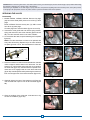
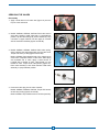
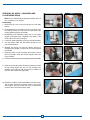
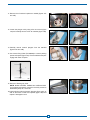
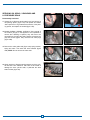
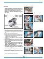
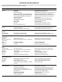
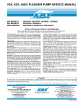
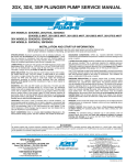
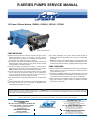
R-SERIES PUMPS SERVICE MANUAL
150 Frame R-Series Models: 152R060, 152R080, 152R100, 157R060
Model 152R100 Shown
PUMP DRIVE-END
●
Maintenance of the drive-end is limited to regular oil changes to assure
optimum lubrication. In case of a new pump, a first oil change is
required after about 20 operating hours. Thereafter, oil changes will only
be necessary every 3000 hours or every 6 months.
●
Fill crankcase with special CAT PUMPS custom-blend, multi-viscosity,
ISO100 petroleum based hydraulic oil (22.4 gallons, 85 liters). Use PN
6116 (16 gallons) or PN 6116 (5 gallons).
●
Oil level can visually be checked at the oil gauge. A correct oil level is
obtained when the oil gauge shows a 3/4-level with the pump stopped.
NOTE: Overfilling with oil may lead to overheating the pump.
●
The surface temperature of the pump’s drive-end should regularly be
checked during the first 50 operating hours of the pump, and thereafter,
once a day.
NOTE: If the thermo pump stickers indicate higher temperatures than
150°F (65°C), change oil or review installation. Temperatures may vary
according to the unit’s surroundings, operating pressure and pump speed.
PUMP LIQUID-END
●
Check the oil level and the oil color daily. A black oil color can indicate
a strong reduction of the lubrication capacity of the oil, overheating or
the use of the wrong oil type. A milky-white oil color can be a sign of
water penetrating the crankcase through the oil seals.
Seal and valve kits can be installed without removing the manifold head.
Service frequency of wear parts will depend on operating pressure,
pump speed and duty-cycle.
●
The degree of prefiltration (minimum 5µ), cleanliness of the surroundings
(sand and dust penetration) and dosification of chemicals (pH 0-3 or 912) will influence the service frequency and may affect seal lifetime.
●
It is possible that due to temperature differences minor oil sweating may
occur.
●
●
Daily inspect the area under and around the pump for oil leakage or spots.
Pumps operated under cavitation conditions or with liquids containing
high oxygen contents or gaseous waters will contribute to premature
wear of pump components.
●
Oil change should occur when the pump’s oil temperature has
decreased to approximately 77°F (25°C).
●
WARNING
All systems require both a primary pressure regulating device (i.e., regulator, unloader) and a secondary pressure safety relief device (i.e., pop-off valve, safety valve).
Failure to install such relief devices could result in personal injury or damage to the pump or to system components. CAT PUMPS does not assume any liability or responsibility
for the operation of a customer’s high pressure system.
Products described hereon are covered by one or more of the following U.S. patents 3558244, 3652188, 3809508, 3920356, 3930756 and 5035580
CAT PUMPS (U.K.) LTD.
World Headquarters
CAT PUMPS
1681 - 94th Lane N.E. Minneapolis, MN 55449 - 4324
Phone (763) 780-5440 — FAX (763) 780-2958
e-mail: [email protected]
www.catpumps.com
1 Fleet Business Park, Sandy Lane, Church Crookham, Fleet
Hampshire GU52 8BF, England
Phone Fleet 44 1252-622031 — Fax 44 1252-626655
e-mail: [email protected]
N.V. CAT PUMPS INTERNATIONAL S. A.
The Pumps with Nine Lives
Heiveldekens 6A, B-2550 Kontich, Belgium
Phone 32- 3- 450.71.50 — Fax 32-3- 450.71.51
e-mail: [email protected] www.catpumps.be
International Inquiries
CAT PUMPS DEUTSCHLAND GmbH
FAX (763) 785-4329
e-mail: [email protected]
Buchwiese 2, D-65510 Idstein, Germany
Phone 49 6126-9303 0 — Fax 49 6126-9303 33
e-mail: [email protected] www.catpumps.de
PN 993295 Rev A 5719
CAUTION: Before commencing with service, shut off drive (electric motor, gas or diesel engine) and turn off water supply to pump. Relieve all discharge
line pressure by triggering gun or opening valve in discharge line.
After servicing is completed, turn on water supply to pump, start drive, reset pressure regulating device and secondary valve, read system pressure
on the gauge at the pump head. Check for any leaks, vibration or pressure fluctuations and resume operation.
SERVICING THE VALVES
Disassembly
1. Models 152R060, 152R080, 152R100: Remove forty-eight
(48) hex socket head (HSH) screws from all six (6) valve
plugs.
Model 157R060: Remove seventy-two (72) HSH screws
from all six (6) valve plugs
Lift valve plugs from valve chambers (figures 1A and 1B).
1A
1B
2A
2B
4A
4B
2. Unscrew the valve guide stud and remove spring retainer,
spring and valve from each valve chamber (figures 2A and
2B). The valve seat will remain in the valve chamber.
3. To remove the valve seat, a special extracting tool is required
figure 3A).
NOTE: The valve seat does not have to be replaced with
every valve kit servicing. Replace only if the valve surfaces
are pitted, grooved or worn. See Data Sheets for valve kits.
Extracting Tool
Claws
Support
3A
4. Place the extractor tool with the claws towards the chamber
until the support’s surface rests on the valve seat. Turn the
extractor 15° until the claws cling under the 3 inner studs of
the valve seat (figure 4A). Pull the extractor upwards. All 3
claws have to be engaged with the inner valve seat studs
(figure 4B). Hold this position while positioning the extractor’s
face onto the upper face of the valve’s chamber (figure 4C).
4C
5. Gradually tighten the nuts of the extractor tool (figure 5A)
until the valve seat is pried out of its valve chamber (figure
5B).
5A
6. Clean the surfaces of the valve seat. Lubricate new o-ring
for ease in installation (figure 6A).
6A
2
5B
SERVICING THE VALVES
Reassembly
1. Apply a small amount of Loctite® 641 (figure 1A) onto the
top rim of the valve seat.
1A
2. Models 152R060, 152R080, 152R100: Place valve seat in
each valve chamber. Install valve seat in a perpendicular
position. Tap the valve seat gently into its chamber by using
a wooden or copper hammer until the upper rim contacts
with the manifold’s shoulder (figures 2A and 2B).
3. Models 152R060, 152R080, 152R100: Place valve, spring,
spring retainer and valve guide stud onto the valve seat.
Torque at 55 ft-lbs (75 Nm) (figures 3A and 3B).
Model 157R060: Place threaded end of the valve through
center hole of tapered surface of valve seat. Slide spring
over threaded end of valve. Apply a small amount of
Loctite® 243 to threads of valve. Hand thread nut onto
threads of valve. Torque at 60 ft-lbs (80 Nm) (figure 3C).
Place valve assembly in each valve chamber. Install valve
assembly in a perpendicular position.
2A
2B
3A
3B
3C
4. Press each valve plug into the valve chamber.
Models 152R060, 152R080, 152R100: Torque HSH screws
at 55 ft-lbs (75 Nm) (figures 4A and 4B).
Model 157R060: Torque HSH screws at 75 ft-lbs (100 Nm).
4A
3
4B
SERVICING OIL SEALS, V-PACKINGS AND
LO-PRESSURE SEALS
NOTE: Prior to disassembly of packings and seals, drain oil
from crankcase to 1/2 capacity.
Disassembly
1. Remove acrylic cover on top of pump with an 8 mm allen
wrench.
2. Lift the packing tool, mounted on the top of the pump, from
its holder and insert one end into one of the holes of the
packing adjuster (figures 2A and 2B).
2A
2B
6A
6B
8A
8B
9A
9B
10A
10B
3. Disassembly and reassembly steps refer to one single
plunger. Accomplish them completely and repeat in the
same order for the other 2 plungers.
4. Loosen the packing adjuster by turning it counterclockwise.
5. Turn the pump’s pulley until the ceramic plunger is in its
most forward position.
6. Separate the plunger rod from the ceramic plunger by
unscrewing the plunger nut with a 50 mm wrench (figures
6A and 6B).
7. Rotate the pulley in order to position the plunger rod in its
most rear position. Push the ceramic plunger toward the
pump manifold.
8. Unscrew and remove the packing adjuster (figures 8A and 8B).
9. Remove two (2) HSH screws and two (2) washers from the
oil seal carrier (figure 9A) with a 6 mm hexagon key.
Carefully remove the oil seal carrier from its chamber by
means of two screwdrivers (figure 9B).
10. Inspect the condition of the oil seal within the oil seal carrier.
The oil seal is located in the interior groove of the oil seal
carrier (figure 10A). Also check the o-ring on the exterior
groove of the oil seal carrier (figure 10B).
4
11. Remove the oil seal and replace as needed (figures 11A
and 11B).
11A
11B
12A
12B
13A
13B
16A
16B
12. Loosen the plunger rod by using a 50 mm wrench (figure
12A) and carefully remove it from its chamber (figure 12B).
13. Carefully remove ceramic plungers from the manifold
(figures 13A and 13B).
14. Use Lantern Ring Puller (PN 998809) to remove packing
spacer and spacer (figure 14A). Ensure stainless steel pins
engage with holes of spacer.
Lantern Ring Puller
14A
15. Remove V-Packings by hand.
NOTE: Models 152R060, 152R080 and 152R100 ONLY.
If V-Packings and spacers cannot be removed, proceed to
disassembly steps 18, 19 and 20.
16.Inspect plunger rods and ceramic plungers (figure 16A), as
well as the stack of seals and spacers (figure 16B) and
replace if damaged or worn.
5
SERVICING OIL SEALS, V-PACKINGS AND
LO-PRESSURE SEALS
Disassembly Continued
17. Inspect the Lo-Pressure seal located in the inner groove of
the packing spacer (figure 17A) and replace as needed.
Also inspect the o-ring located at the exterior of the packing spacer, and replace as needed (figure 17B).
17A
17B
18A
18B
19A
19B
18.Models 152R060, 152R080, 152R100: If after removal of
the ceramic plunger, it still appears to be impossible to
remove the V-Packing or spacers, they will have to be
removed from the inlet valve side. Remove all twenty-four
(24) HSH screws (figure 18A). Remove inlet valve plugs
(figure 18B).
19.Remove the valve guide stud (figure 19A) spring retainer,
spring and valve from each inlet valve chamber (figure
19B). NOTE: Do not remove the valve seat.
20.Gently push the V-Packings and/or spacers out of the cylinder line with a fine metal bar. Take care not to scratch or
damage the inner cylinder walls, in particular the valve
seat’s surface (figure 20).
20
6
Reassembly
1. Assemble a complete seal stack onto the appropriate seal
installation plunger tool in the correct sequence (figure 1A).
Slightly lubricate the outside diameter of the V-Packing with
glycerine to facilitate their installation in the chamber.
NOTE: Use the appropriate seal installation tools for each
pump model.
PUMP MODEL
152R060, 157R060 ...........................
152R080 ............................................
152R100 ............................................
SLEEVE
PN 998803
PN 998805
PN 998807
Seal Stack
1A
PLUNGER
PN 998804
PN 998806
PN 998808
4A
4B
V-Packing Arrangement
Seal Installation
Plunger Tool
Seal Housing
Seal Installation Sleeve Tool
5A
2. Lubricate outside diameter of appropriate sleeve tool and
install tapered end into seal housing. Place plunger tool
with V-Packing into large end of sleeve tool and press into
place.
3. Remove sleeve tool and then plunger tool.
4. Carefully install the ceramic plunger in the manifold’s chamber (figure 4A) and then slide the spacer and packing spacer over the ceramic plunger (figure 4B).
5. Thread on the packing adjuster 2 or 3 turns but do not tighten it (figure 5A).
6A
6B
6. Install plunger rod (figure 6A) and connect it to the connecting
rod. Use a 50 mm wrench to tighten-up. Torque at 110 ft-lbs
(150 Nm) (figure 6B).
7. Lubricate the outer rim of the oil seal carrier and place it in its
chamber. Install two (2) washers and two (2) HSH screws.
Torque at 11 ft-lbs (15 Nm) (figure 7A).
8. Turn the pulley to position the plunger rod in the most forward position. Pull the ceramic plunger backwards until
both threads meet. Tighten with a 50 mm wrench. Torque
at 90 ft-lbs (120 Nm) (figure 8A).
7A
9. Tighten the packing adjuster using the Packing Tool (figure 9A).
10.Repeat the same steps for the other 2 plungers. Reinstall
the acrylic panel before beginning operation.
Loctite is a registered trademark of the Henkel Corporation.
8A
7
9A
DIAGNOSIS AND MAINTENANCE
This service manual is designed to assist you with the disassembly and reassembly of your pump. The following guide will assist in defining the
problem, citing probable cause(s) and providing the solution(s).
PROBLEM
PROBABLE CAUSE
SOLUTION
Low flow
•Incorrect RPM.
•Belt slippage.
•Air leak in inlet plumbing.
•Pressure gauge inoperative or not registering accurately.
•Relief valve stuck, partially plugged or improperly adjusted.
•Inlet suction strainer (filter) clogged or improperly sized.
•Abrasives in pumped liquid.
•Leaky discharge hose.
•Inadequate liquid supply (NPSH).
•Pump not filling.
•Severe cavitation.
•Worn seals.
•Worn or dirty inlet/discharge valves.
•Change drive ratio or correct motor speed.
•Tighten belt(s) or install new belt(s).
•Tighten fittings and hoses and purge air. Use PTFE liquid or tape.
•Check with new gauge. Replace worn or damaged gauge.
•Clean/adjust relief valve. Replace worn seats/valves and o-rings.
•Clean filter. Use adequate size filter. Check more frequently.
•Install proper filter.
•Replace discharge hose with proper rating for system.
•Increase inlet pressure or line size or minimize elbows.
•Prime pump. Increase inlet pressure.
•Check inlet conditions.
•Install new seal kit. Increase frequency of service.
•Clean inlet/discharge valves or install new valve kit.
Pulsation
•Faulty Pulsation Dampener.
•Foreign material trapped in inlet/discharge valves.
•Check precharge. If low, recharge, or install a new dampener.
•Clean inlet/discharge valves or install new valve kit.
•Worn V-Packings or Lo-Pressure Seals.
•Excessive wear to seals and V-Packings.
•Install new seal kit. Increase frequency of service.
•Install new seal kit. Increase frequency of service. Change oil.
Water leak
•Under the manifold
•Into the crankcase
Knocking noise
•Inlet supply
•Bearing, Connecting Rod or
Crosshead Pins
•Pulley
•Manifold head
•Crankcase
•Inadequate inlet liquid supply.
•Broken or worn bearing, connecting rod or crosshead pins.
•Check liquid supply. Increase line size, pressurize.
•Replace bearing, connecting rod or crosshead pins.
•Loose pulley on crankshaft.
•Air entrapped in manifold head.
•Low oil level.
•Check key and tighten set screw.
•Purge air from manifold head.
•Refill oil level. Inspect for damage if very low.
Oil leak
•Crankcase oil seals.
•Crankshaft oil seals and o-rings.
•Drain plug
•Bubble gauge
•Rear cover
•Filler cap
•Worn crankcase oil seals.
•Worn crankshaft oil seals or o-rings on bearing cover.
•Loose drain plug.
•Loose bubble gauge or worn bubble gauge gasket.
•Loose rear cover.
•Loose filler cap or excessive oil in crankcase.
•Replace crankcase oil seals. Check for contaminated oil.
•Remove bearing cover and replace o-rings and/or oil seals.
•Tighten drain plug.
•Tighten bubble gauge or replace gasket.
•Install sealant and tighten rear cover.
•Tighten filler cap. Check for proper oil level.
•Restricted inlet or air entering the inlet plumbing
•Stuck inlet/discharge valves.
•Leaking V-Packings or Lo-Pressure seals.
•Loose piston rods, bearings, crosshead pins or connecting
rod screws.
•Correct inlet size plumbing. Check for air tight seal.
•Clean out foreign material or install new valve kit.
•Install new seal kit. Increase frequency of service.
•Tighten, adjust or replace.
•Scored plungers or plunger rods.
•Over pressure to manifold head.
•Abrasive material in the liquid being pumped.
•Excessive pressure and/or temperature of pumped liquid.
•Running pump dry.
•Starving pump of adequate liquid.
•Improper installation of packings.
•Improper packing selection.
•Replace plungers or plunger rods.
•Reduce inlet pressure per specifications. Install new seal kit.
•Install proper filtration at pump inlet and clean regularly.
•Check pressure and inlet liquid temperature are within limits.
•DO NOT RUN PUMP WITHOUT LIQUID.
•Increase line one size larger than inlet port size.
•Install per instructions.
•Select correct seal kit for plunger size.
Pump runs extremely rough
•Inlet conditions
•Pump valves
•Pump seals
•Drive-end
Premature seal failure