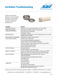
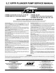
1
Stainless Steel Pressure Regulator Models features l l l l l 7361 7363 specifications Maintains full pressure while running in idle for quick return to system pressure. Offers pump protection against pressure fluctuations and system changes. Minimum pressure fluctuations with the alternating use of multiple guns and nozzles. Top adjusting handle and locking nut to secure exact pressure setting. No external moving parts. Stainless Steel and FPM internal parts for temperature and liquid compatibility. U.S. Measure MODEL 7361 Flow Range............................ 10-60 GPM Pressure Range...................400-1000 PSI MODEL 7363 Flow Range............................ 10-60 GPM Pressure Range...................600-1800 PSI Metric Measure (38-227 L/M) (30-70 BAR) (38-227 L/M) (45-125 BAR) Common Specifications Max. Temperature............................180°F (82°C) Inlet Port...................................... 1” NPTF (1” NPTF) By-Pass Port.........................1-1/4” NPTF (1-1/4” NPTF) Weight........................................... 6.2 lbs. (2.8 kg) Dimensions....................9.1 x 3.43 x 2.38” (231x 87x 60.45 mm) All High Pressure Systems require a primary pressure regulating device (i.e. regulator, unloader) and a secondary pressure relief device (i.e. pop-off valve, relief valve). Failure to install such relief devices could result in personal injury or damage to pump or property. CAT PUMPS does not assume any liability or responsibility for the operation of a customer’s high pressure system. Read all CAUTIONS and WARNINGS before commencing service or operation of any high pressure system. The CAUTIONS and WARNINGS are included in each service manual and with each Data sheet. CAUTIONS and WARNINGS can also be viewed online at www.catpumps.com/cautions-warnings or can be requested directly from CAT PUMPS. “Customer confidence is our greatest asset” Read all CAUTIONS and WARNINGS before commencing service or operation of any high-pressure system SELECTION PRESSURE ADJUSTMENT This pressure regulator is designed for systems with single or multiple pumps, solenoid (gate) valves, nozzles, standard or “weep” guns. 1. Setting and adjusting the regulator pressure must be done with the system “on”. 2. Start the system with regulator backed off to the lowest pressure setting (counterclockwise direction). Note: For multiple pump systems, it is best to use a pressure regulator not a pressure sensitive regulating unloader. 3. Squeeze the trigger and read the pressure on the gauge at the pump. This regulator should meet both the desired system flow (combined nozzle flow rate requirement) and the desired system pressure. Note: Do not read the pressure at the gun or nozzle. 4. If more pressure is desired, release the trigger, turn adjusting handle one quarter turn in clockwise direction. NOTICE: Operation below the minimum flow of the regulator causes the regulator to cycle or chatter. Operation above the maximum flows of the regulator causes premature regulator wear, regulator cycling and prevents attaining desired system pressure. 5. Squeeze the trigger and read the pressure. 6. Repeat this process until desired system pressure is attained. 7. Once the desired system pressure is reached, stop turning the adjusting handle and thread lock nut down towards upper body of regulator to lock in place. INSTALLATION These regulators operate properly when mounted in any direction; however, it is preferred to keep the plumbing to a minimum and the adjusting cap easily accessible. The best mounting location is directly on the pump discharge manifold head or in discharge line using a “T” fitting. Flexible, high pressure hose (minimum single wire braid) should be at least the size of the regulator ports when plumbing to and from the regulator. NOTICE: A minimum by-pass flow of 10% of the regulator rated flow is required for proper regulator performance. If the entire output is directed through the nozzles (zero by-pass) the “cushioning” feature of the by-pass liquid is eliminated and the regulator can malfunction or wear prematurely. 8. If desired system pressure cannot be reached, review TROUBLESHOOTING chart. The inlet connection is located on the side and is a 1” NPTF sized port. Plumb into this port for the discharge flow from the pump. 9. When servicing existing systems, back off lock nut. 10.Follow adjustment procedures as stated above for new regulators. The by-pass connection is located on the bottom and is a 1-1/4” NPTF sized port. By-pass fluid is directed out of this port and can be routed to a reservoir or to a drain. Note: Do not adjust regulators pressure setting to compensate for a worn nozzle. Check the nozzle as part of the regular maintenance and replace if worn. OPERATION Note: A secondary pressure relief device (i.e., pop-off valve) should be used along with this pressure regulator. Final adjustment for the relief valve should relieve at 200 psi above the system operating pressure. These pressure regulators maintain established system pressure in the discharge line and at the pump head when the trigger gun is closed, solenoid (gate) valve is closed or the nozzles are clogged, thus by-passing all unrequired flow. Squeezing the trigger gun or opening the solenoid (gate) valve allows for a quick return to established system pressure. TYPICAL REGULATOR INSTALLATION 1 Pressure Gauge 5 1 2 Relief Valve Shown as a secondary relief valve 3 3 Pulsation Dampener 4 Pressure Regulator 5 Triplex Plunger Pump 2 DISCHARGE 4 BY-PASS Read all CAUTIONS and WARNINGS before commencing service or operation of any high-pressure system SERVICING Disassembly: 1. Disconnect by-pass and inlet plumbing from regulator. 2. Remove regulator from pump. 3. Secure lower body of regulator in a vise with adjusting handle facing up. 4. Remove adjusting handle and screw from upper body. 5. Remove upper body by unthreading from lower body. 6. Remove first spring retainer, spring and second spring retainer from lower body. 7. Remove lower body from vise. 8. Place lower body upside down on a flat surface with by-pass port facing up. Grasp lower body and gently tap against flat surface. Piston guide and ball will fall out. 9. Grasp lower body and gently tap against flat surface to remove piston insert, piston and spring. 10.Separate piston and spring from piston insert. 11.Place lower body with by-pass port facing up on flat surface. Using a tool with the same diameter as that of the seat, drive out seat. NOTICE: Exercise extreme caution to avoid contact and damage to the inside diameter of the piston insert, lower body sealing areas and seat. Exercise extreme caution to avoid contact and damage to the outside diameter of the piston insert, piston and seat. Note: With the regulator completely disassembled, inspect sealing area where the seat and piston insert makes contact within the lower body of the regulator for grooves, pitting and wear. If damage is found, stop the repair and replace with new lower body or complete new regulator. If not, proceed with reassembly. TROUBLESHOOTING Cycling/Chattering l Too little flow for valve specifications. Air in system, poor connections. l Inlet seals in pump worn. l O-ring in gun worn. System will not build up to pressure l Pressure drop l Pressure spikes while in by-pass l l Nozzle worn. Improper nozzle size for system specs. l Foreign material trapped in seat. l Nozzles worn. Piston and seat in regulator worn. l Air in system, poor connections. l Insufficient flow to pump. l Filter clogged. Check and clean regularly. l Minimum by-pass of 10% not present. pressure adjustment made for worn nozzle. REPLACE NOZZLE. Reset system pressure. lExcessive l O-ring around piston worn or piston Leakage from regulator vent hole retainer scored. Service with o-ring kit. Reassembly: 1. Place lower body with by-pass port facing down on a flat surface. 2. Lubricate outside diameter of seat. Press seat into lower body with small diameter surface facing down. Ensure seat lip rests squarely on lower body surface. 3. Place lower body in a vise with large diameter hole facing up. 4. Lubricate and install o-ring onto outer diameter of piston insert and into inside diameter of piston insert. Press piston insert with small diameter down into lower body. 5. Install flat washer into piston insert so it rests on top of o-ring. 6. Place spring on top of flat washer. 7. Lubricate and install o-ring, then backup-ring onto outside diameter of piston. 8. Place piston into spring. 9. Place piston guide on top of piston. Insert ball into center hole of piston guide. 10.Place first spring retainer with stepped side facing up onto piston guide. 11.Install spring onto first spring retainer and then place second spring retainer on spring with stepped side facing down. 12.To install the upper body onto the lower body, use the hole in the upper body to fit screwdriver through to support the stacked internal parts. Thread upper body onto lower body while holding parts in place with screwdriver. Remove screwdriver. 13.Thread in adjusting handle with screw through hole in upper body. 14.Re-install regulator onto pump. 15.Reconnect by-pass and inlet plumbing to regulator. 16.Proceed to PRESSURE ADJUSTMENT. Approximate Pressure Reading at Gauge Gauge Between Pump/Regulator Gauge Between Regulator/Gun-Nozzle-Valve System in operation (gun open) system pressure system pressure 200-300 PSI above system pressure 200-300 PSI above system pressure System in by-pass (all guns,valves closed) exploded view Cutaway 401 403 405 410 406 408 426 427 432 435 410 468 438 INLET PORT 468 440 445 436 Convenient adjusting handle with locking nut to secure desired system pressure. Leaking from external weep hole is signal for immediate maintenance of worn o-rings. Stainless Steel ball, seat and piston offer extended life and liquid compatibility. Durable FPM o-rings assure greater liquid and temperature compatibility. All Stainless Steel lower body and wet end parts for strength and corrosion resistance. BY-PASS PORT PARTS LIST item descriptionMODEL NUMBER 7361MATL 401 Handle, Adjusting 30948 NY R 403 Nut, Lock 30933 S 405 Adjuster, Pressure 30932 S 406 Body, Upper— STNP 408 Spring 30935 STL R 410 Retainer, Spring 34289 BB R 426 Guide, Piston 30927 BB R 427 Insert, Piston 30926 SSA R 432 Ball 30936 SS R 435 Piston 30924 SS R 436 Seat 30918 SSA R 438 Spring 30934 SS 440 Body, Lower Hex — SS 445 Washer, Flat 30925 SS 468 Kit, O-Ring 30950 FPM R 490 Bracket, Panel Mount (Not Shown) 30947 BB qty 7363MATL 30948 NY R 30912 STZP R 30932 S — STNP 30946 STL R 34289 BB R 30927 BB R 30926 SSA R 30936 SS R 30924 SS R 30918 SSA R 30934 SS — SS 30925 SS 30950 FPM R 30947 BB 1 1 1 1 1 2 1 1 1 1 1 1 1 1 1 1 Bold print part numbers are unique to a particular model. Italics are optional items. R Components comply with RoHS Directive. Material Codes (Not Part of Part Number): BB=Brass FPM=Fluorocarbon NY=Nylon STNP=Steel/Nickel Plated S=304SS SS=316SS SSA=316SS Condition A STL=Steel Cat Pumps (U.K.) LTD. World Headquarters Cat Pumps 1681 - 94th Lane N.E. Minneapolis, MN 55449-4324 Phone (763) 780-5440 — FAX (763) 780-2958 e-mail: [email protected] www.catpumps.com International Inquiries FAX (763) 785-4329 e-mail: [email protected] “Original Instructions” 1 Fleet Business Park, Sandy Lane, Church Crookham FLEET, Hampshire, GU52 8BF, England Phone Fleet 44 1252-622031 — Fax 44 1252-626655 e-mail: [email protected] www.catpumps.co.uk N.V. Cat Pumps INTERNATIONAL S.A. The Pumps with Nine Lives Heiveldekens 6A, B-2550 Kontich, Belgium Phone 32-3-450.71.50 — Fax 32-3-450.71.51 e-mail: [email protected] www.catpumps.be Cat Pumps DEUTSCHLAND GmbH Buchwiese 2, D-65510 Idstein, Germany Phone 49 6126-9303 0 — Fax 49 6126-9303 33 e-mail: [email protected] www.catpumps.de PN 993310 Rev A 01/10 4919