1
Service Manual
MODEL:
CFT35A-R
CFT50A-R
CFT70A-R
CFT100A-R
CFT140A-R
CFT170A-R
Dimensions
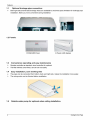
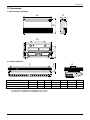
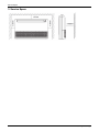
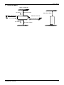
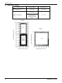
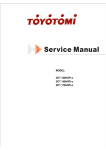
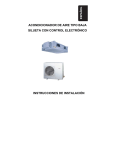
2. Dimensions
a. Wall mounting installation
A
B
C
E
D
>20mm
b. Ceiling installation
F
G
Capacity (Btu/h)
A
B
C
D
E
F
G
12000-24000
990
660
203
505
506
907
200
30000-36000
1280
660
203
795
506
1195
200
48000-60000
1670
680
240
1070
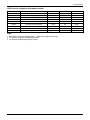
Note: The dimension of 12000Btu/h, 18000Btu/h and 24000Btu/h are the same.
The dimension of 30000Btu/h and 36000Btu/h are the same.
The dimension of 48000Btu/h and 60000Btu/h are the same.
450
1542
200
Ceiling & Floor Type
5
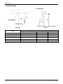
Service Space
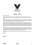
3. Service Space
6
Ceiling & Floor Type
Wiring Diagrams
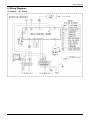
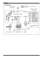
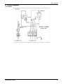
4. Wiring Diagrams
CFT 35A-Ri
CFT 50A-Ri
Ceiling & Floor Type
7
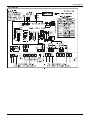
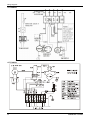
Wiring Diagrams
CFT 70A-Ri
8
Ceiling & Floor Type
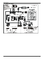
Wiring Diagrams
CFT 100A-Ri
Ceiling & Floor Type
9
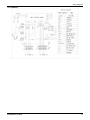
Wiring Diagrams
CFT 140A-Ri CFT 170A-Ri
10
Ceiling & Floor Type
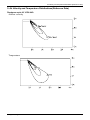
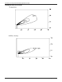
Air Velocity and Temperature Distributions(Reference Data)
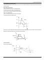
5. Air Velocity and Temperature Distributions(Reference Data)
Discharge angle 60° (CEILING)
Airflow velocity
Temperature
Ceiling & Floor Type
11
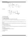
Air Velocity and Temperature Distributions(Reference Data)
Discharge angle 60°(FLOOR)
Temperature
Airflow velocity
12
Ceiling & Floor Type
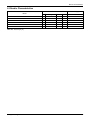
Electric Characteristics
6. Electric Characteristics
Model
CFT 35A-Ri
Indoor Units
Hz
Voltage
Min.
Power Supply
Max.
MFA
50
220-240V
198V
254V
16
CFT 50A-Ri
50
220-240V
198V
254V
16
CFT 70A-Ri
50
220-240V
198V
254V
25
CFT 100A-Ri
50
380-415V
342V
418V
20
CFT 140A-Ri
50
380-420V
342V
440V
20
CFT 170A-Ri
Note:
MFA: Max. Fuse Amps. (A)
50
380-420V
342V
440V
20
Ceiling & Floor Type
13
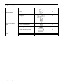
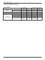
Sound Levels
7. Sound Levels
Ceiling
Model
Noise level dB(A)
H
M
L
43
41
38
CFT 50A-Ri
43
41
38
CFT 70A-Ri
45
43
40
CFT 100A-Ri
45
43
40
CFT 140A-Ri
50
47
45
CFT 170A-Ri
50
49
47
CFT 35A-Ri
14
Floor
Ceiling & Floor Type
Accessories
8. Accessories
Name
Shape
Quantity
1.Hook
2
2.Hanging arm
2
3. Remote controller
1
4. Remote controller holder
1
5. Mounting screw (ST2.9×10-C-H)
2
6. Alkaline dry batteries (AM4)
2
7. Owner's manual
1
8. Installation manual
1
9. Remote controller manual
1
Installation fittings
Remote controller & Its
holder
Others
Ceiling & Floor Type
15
The Specification of Power
9. The Specification of Power
Cooling & Heating
Type
Phase
Power
Frequency and Voltage
Circuit Breaker/ Fuse (A)
30000-60000
Btu/h
3-phase
380-415V,
50Hz
25/20
3×2.5
3×2.5
3×4.0
5×2.5
Ground Wiring
2.5
2.5
4.0
2.5
Outdoor Unit Power Wiring
3×2.5
3×2.5
3×4.0
5×2.5
Strong Electric Signal
2×1.0
2-core shield
wire 2×0.75
2
mm /2×0.5
2
mm
3×1.5
3×1.0
3×1.0
2-core shield
wire 2×0.75
2
mm
2-core shield
wire 2×0.75
2
mm
Weak Electric Signal
16
1-phase
220-240V,
50Hz
40/25
30000-36000
Btu/h
1-phase
220-240V,
50Hz
50/30
24000Btu/h
2
Indoor Unit Power Wiring (mm )
Indoor/Outdoor
2
Connecting Wiring (mm )
12000-18000
Btu/h
1-phase
220-240V,
50Hz
20/16
Ceiling & Floor Type
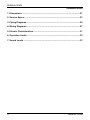
Outdoor Units
Outdoor Units
1. Dimensions .................................................................................................21
2. Service Space..............................................................................................23
3. Piping Diagrams..........................................................................................24
4. Wiring Diagrams .........................................................................................27
5. Electric Characteristics ..............................................................................31
6. Operation Limits .........................................................................................32
7. Sound Levels ..............................................................................................33
20
Outdoor Units
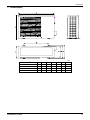
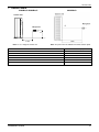
Dimensions
1. Dimensions
mm
Outdoor Units
Model
CFT 35A-Ro
CFT 50A-Ro
A
780
762
B
548
530
C
266
290
D
300
315
E
241
270
F
250
282
H
547
593
CFT 70A-Ro
842
560
335
360
312
324
695
CFT 100A-Ro
990
624
366
396
340
354
966
21
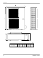
Dimensions
mm
Model
22
A
B
C
D
E
F
H
CFT 140A-Ro
900
590
378
400
330
340
1167
CFT 170A-Ro
900
590
378
400
330
340
1167
Outdoor Units
Service Space
2. Service Space
(Wall or obstacle)
Air inlet
More than 30cm
Air inlet
More than 30cm
More than 60cm
Maintain channel
More than 60cm
Air outlet
Outdoor Units
More than 200cm
23
Piping Diagrams
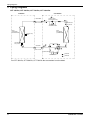
3. Piping Diagrams
CFT 35A-Ro, CFT 50A-Ro, CFT 70A-Ro, CFT 100A-Ro
INDOOR
OUTDOOR
LIQUID SIDE
CHECK VALVE
(Heating Model only)
2-WAY VALVE
T3 Condenser
temp. sensor
CAPILIARY TUBE
HEAT
EXCHANGE
(EVAPORATOR)
HEAT
EXCHANGE
(CONDENSER)
T1 Room temp.
sensor
T2 Evaporator
temp. sensor
GAS SIDE
4-WAY VALVE
3-WAY VALVE
ACCUMULATOR
COOLING
COMPRESSOR
HEATING
For CFT 35A-Ro, CFT 50A-Ro, CFT 70A-Ro the accumulator is not included.
24
Outdoor Units
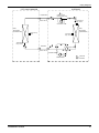
Piping Diagrams
CFT 140A-R INDOOR
OUTDOOR
CHECK VALVE
(Heating Model only)
LIQUID SIDE
2-WAY VALVE
T3 Condenser
temp. sensor
CAPILIARY TUBE
HEAT
EXCHANGE
(CONDENSER)
HEAT
EXCHANGE
(EVAPORATOR)
T1 Room temp.
sensor
T4 Ambient
temp. sensor
T2 Evaporator
temp. sensor
GAS SIDE
4-WAY VALVE
3-WAY VALVE
ACCUMULATOR
COOLING
COMPRESSOR
Outdoor Units
HEATING
25
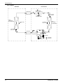
Piping Diagrams
CFT 170A-R
INDOOR
OUTDOOR
LIQUID SIDE
CHECK VALVE
(Heating Model only)
2-WAY VALVE
T3 Condenser
temp. sensor
CAPILIARY TUBE
HEAT
EXCHANGE
(EVAPORATOR)
HEAT
EXCHANGE
(CONDENSER)
T4 Ambient
temp. sensor
T1 Room temp.
sensor
T2 Evaporator
temp. sensor
GAS SIDE
4-WAY VALVE
3-WAY VALVE
Accumulator
Compressor
Oil separator
COOLING
Oil return Capillary
26
HEATING
Outdoor Units
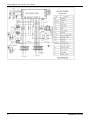
Wiring Diagrams
4. Wiring Diagrams
CFT 35A-Ro
Outdoor Units
27
Wiring Diagrams
CFT 50A-Ro
CFT 70A-Ro
28
Outdoor Units
Wiring Diagrams
CFT 100A-Ro
Outdoor Units
29
Wiring Diagrams CFT 140A-Ro, CFT 170A-Ro
30
Outdoor Units
Electric Characteristics
5. Electric Characteristics
Model
Outdoor Unit
Hz
Voltage
Min.
Max.
50
220~240V
198V
254V
CFT 50A-Ro
50
220~240V
198V
254V
CFT 70A-Ro
50
220~240V
198V
254V
CFT 100A-Ro
50
380~420V
342V
440V
CFT 140A-Ro
50
380~420V
342V
440V
50
380~420V
342V
440V
CFT 35A-Ro
CFT 170A-Ro
Outdoor Units
31
Operation Limits
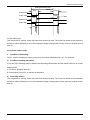
6. Operation Limits
Temperature
Mode
Cooling operation
Heating operation
17đЊ32đ
0đЊ30đ
Room temperature
18đЊ43đ
δ-7đЊ43đφFor the
models with low
temperature cooling
systemε
Outdoor temperature
-7đЊ24đ
Cooling
45
43
40
35
STD
Heating
25
25
24
20
18
20
Outdoor temperature(ć DB)
Outdoor temperature(ć DB)
30
15
10
With Low
Ambient
Cooling
System
5
0
-5
-7
-10
10
15 17 20
25
30 32 35
Indoor temperature(ć WB)
32
15
10
STD
5
0
-5
-7
-10
0
5
10
15
20
25
30
Indoor temperature(ć WB)
Outdoor Units
Sound Levels
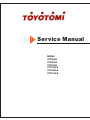
7. Sound Levels
12000Btu/h-48000Btu/h
60000Btu/h
Outdoor Unit
Microphone
H
1.0m
Note: H= 0.5 × height of outdoor unit
Model
Noise level dB(A)
CFT 35A-Ro
43
CFT 50A-Ro
54
CFT 70A-Ro
55
CFT 100A-Ro
57
CFT 140A-Ro
59
CFT 170A-Ro
Outdoor Units
Note: The point A is in the middle of the whole outdoor panel.
59
33
Electrical
Control
Electrical Control System
1. Electrical Control Function ........................................................................35
2. Troubleshooting..........................................................................................45
3. Controller........................................................................... 䭏䈥!ᵠᇐѿҜㆴȾ
34
Electrical
Control
Electrical Control Function
1. Electrical Control Function
1.1 Definition
T1: Indoor room temperature
T2: Coil temperature of evaporator
T3: Coil temperature of condenser
T4: Outdoor ambient temperature
T5: Compressor discharge temperature
1.2 Main Protection
1.2.1 Time Delay at restart for compressor.
1.2.2 Sensor protection at open circuit and breaking disconnection.
1.2.3 Phase check function
If the phase sequence is detected wrong or lack of 1 or 2 phaseWKHXQLWZRQ¶WVWDUWDQGWKHUHLVHUURUFRGH
displayed on outdoor PCB.
1.2.4 Low pressure check function
The low pressure switch should be always closed. If it is open, the system will stop until the fault is cleared.
During defrosting procedure and 4 miQXWHVDIWHUGHIURVWLQJHQGVORZSUHVVXUHVZLWFKZRQ¶WEHFKHFNHG
Note: The system will not check if the protection could be cleared in 30 seconds after the protection occurs.
,IWKLVSURWHFWLRQRFFXUVWLPHVLWZRQ¶WUHFRYHUDXWRPDWLFDOO\XQWLOWKHPDLn power is cut off.
1.2.5 Over-current protection
When compressor is running, if the current is over twice of the rated for 3 seconds, the compressor will stop
and an error code will be displayed on the outdoor PCB. If the current becomes normal, the compressor will
restart after 3 minutes.
Note: 7KHFXUUHQWZRQ¶WEHFKHFNHGZLWKLQVHFRQGVDIWHUWKHFRPSUHVVRUVWDUWV7KHV\VWHPZLOOQRWFKHFN
if the protection could be cleared in 30 seconds after the protection occurs.
Electrical Control
35
Electrical Control Function
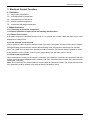
1.3 Operation Modes and Functions
1.3.1 Fan mode
(1) Outdoor fan and compressor stop.
(2) Temperature setting function is disabled, and no setting temperature is displayed.
(3) Indoor fan can be set to high/(med)/low/auto.
(4) The louver operates same as in cooling mode.
(5) Auto fan:
Big Cassette
T1
High
27qC
24qC
Low
Compact Cassette
T1
High
27qC
25qC
Low
Others type
T1
27
High
26
Medium
24
Low
1.3.2 Cooling Mode
1.3.2.1 Outdoor fan running rules
For 1-phase outdoor units:
The On-off outdoor units have single fan speed. The outdoor fan will run following the compressor except
when AC is in evaporator high temp. protection in heating mode ,condenser high temp. protection in cooling
mode, defrosting mode and the current protection.
For 3-phase outdoor units:
36
Electrical Control
Electrical Control Function
High
33
30
Low
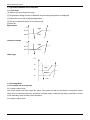
1.3.2.2 Indoor fan running rules
In cooling mode, indoor fan runs all the time and the speed can be selected as high, (medium), low and auto.
The auto fan:
Big cassette:
T1-TS
4qC
High
1qC
Low
Compact cassette:
T1-TS
3qC
High
1qC
Low
Others type
T1-Ts
4
High
3
Medium
1
Low
Electrical Control
37
Electrical Control Function
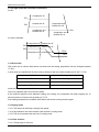
1.3.2.3 Low evaporator coil temperature T2 protection
T2
On
TE6
TE5
Off
When the evaporator coil temp.T2 keeps lower than TE5 for 3 minutes, the compressor and outdoor fan will
shut off. When T2 is higher than TE6, the compressor and outdoor fan will restart up.
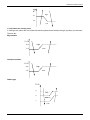
1.3.2.4 Condenser high temperature T3 protection
T3
Off
TE12
TE13
On
:KHQ77(2 for Time1, the compressor will shut off. When T3ψTE13,the compressor will restart.
1.3.3 Heating Mode(For heat pump models)
1.3.3.1 Outdoor fan running rules:
For 1-phase outdoor units:
The On-off outdoor units have single fan speed. The outdoor fan will run following the compressor except
when AC is in evaporator high temp. protection in heating mode ,condenser high temp. protection in cooling
mode, defrosting mode and the current protection.
For 3-phase outdoor units:
18
Low
16
High
38
Electrical Control
Electrical Control Function
1.3.3.2 Indoor fan running rules:
When the compressor is on, the indoor fan can be set to high/med/low/auto. And the anti-cold wind function
has the priority.
Anti-cold wind function:
When evaporator coil temp.T2 is getting higher,
T2>TE2, the indoor fan will run at setting speed.
TE1<T2<TE2, the indoor fan will run at low speed.
When T2 is getting lower,
TE4<T2<TE3,the indoor fan will run at low speed.
T2<TE4, the indoor fan will shut off.
T2
Setting
TE2
TE1
TE3
Low
TE4
Off
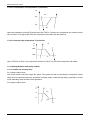
Only for DL: If the compressor stops caused by the room temperature rising, the indoor fan will follow the
below rules. During this period, the anti-cold-wind is disabled.
T2
Setting
TE14+2ć
TE14
Low for15s, then
off
Auto fan action:
For DL: floor installation
Electrical Control
39
Electrical Control Function
For DL ceiling installation & duct::
For cassette:
T1-TS
3qC
1qC
Low
High
1.3.3.3 Defrosting modeφ
For 1-phase outdoor units:
z
Condition of defrosting:
AC will enter defrosting mode if any of the following items is satisfied.
A: For DL, high static pressure duct & cassette :The compressor keeps running over 40 minutes and T3ψ
-2đ
For A5 duct: T3<0đ and the compressor keeps running over 45 minutes. Meanwhile T3ψ-3đ for
3minutes.
B: After the last defrosting, the time that the outdoor fan is off but the compressor is on in high T2 protection
cumulates up to 90 minutes.
z
Condition of ending defrosting:
If any one of the following items is satisfied, the defrosting will terminate and the machine will turn to normal
heating mode.
A: T3 rises to be higher than 20ć.
B: The machine has run for 10 minutes in defrosting.
z
Defrosting actionφ
For A5 duct:
40
Electrical Control
Electrical Control Function
Setting defrosting time
45S
45S
Compressor
4 way valve
40S
40S
Outdoor fan
Indoor fan
10S
For the others type::
The compressor is running, and 4-way valve and outdoor fan stop. The indoor fan works as anti-cold wind
procedure. When defrosting is over, the compressor keeps running and the 4-way valve and outdoor fan will
start up.
For 3-phase outdoor units:
z
Condition of defrosting:
T3<0đ and the compressor keeps running over 45 minutes. Meanwhile T3ψ-3đ for 3minutes.
z
Condition of ending defrosting:
If any one of the following items is satisfied, the defrosting will terminate and the machine will turn to normal
heating mode.
A: T3 rises to be higher than 20ć.
B: The machine has run for 10 minutes in defrosting.
z
Defrosting actionφ
The compressor is running, and 4-way valve and outdoor fan stop. The indoor fan works as anti-cold wind
procedure. When defrosting is over, the compressor keeps running and the 4-way valve and outdoor fan will
start up.
Electrical Control
41
Electrical Control Function
1.3.3.4 High evaporator coil temp.T2 protection:
For DL:
TE7
TE8
Compressor off
Outdoor fan off
Compressor and
Outdoor fan off
Compressor and
Outdoor fan on
TE9
Compressor and
Outdoor fan on
For duct & cassette:
Compressor off Outdoor fan off
TE9
Compressor on Outdoor fan off
TE8
TE10
Compressor on Outdoor fan on
TE11
1.3.4 Auto-mode
This mode can be chosen with remote controller and the setting temperature can be changed between
17~30đ.
In auto mode, the machine will choose cooling, heating or fan-RQO\PRGHDFFRUGLQJWRǻ7ǻ7 7-Ts).
ǻ7 7-Ts
Running mode
ǻ7ϊ2đ
Cooling
-1ǻ72đ
Fan-only
ǻ7-1đ
Heating
Indoor fan will run at auto fan of the relevant mode.
The louver operates same as in relevant mode.
If the machine switches mode between heating and cooling, the compressor will keep stopping for 15
minutes and then choose mode according to T1-Ts.
If the setting temperature is modified, the machine will choose running function again.
1.3.5 Drying mode
1.3.5.1 The indoor fan will keep running at low speed.
1.3.5.2 All protections are active and the same as that in cooling mode.
1.3.5.3 The louver operates the same as in cooling mode.
1.3.6 Timer function
1.3.6.1 Timing range is 24 hours.
42
Electrical Control
Electrical Control Function
1.3.6.2 Timer on. The machine will turn on automatically when reaching the setting time.
1.3.6.3 Timer off. The machine will turn off automatically when reaching the setting time.
1.3.6.4 Timer on/off. TKHPDFKLQHZLOOWXUQRQDXWRPDWLFDOO\ZKHQUHDFKLQJWKHVHWWLQJ³RQ´WLPHDQGWKHQ
WXUQRIIDXWRPDWLFDOO\ZKHQUHDFKLQJWKHVHWWLQJ³RII´WLPH
1.3.6.5 Timer off/on. TKHPDFKLQHZLOOWXUQRIIDXWRPDWLFDOO\ZKHQUHDFKLQJWKHVHWWLQJ³RII´WLPH, and then
WXUQRQDXWRPDWLFDOO\ZKHQUHDFKLQJWKHVHWWLQJ³RQ´WLPH
1.3.6.6 The timer function will not change the AC current operation mode. Suppose AC is off now, it will not
start up firstly after setting the ³timer off´ function. And when reaching the setting time, the timer LED will be
off and the AC running mode has not been changed.
For high static pressure duct & cassette: The timer function will change the AC current operation mode.
6XSSRVHXVHUVVHWWKH³WLPHURII´IXQFWLRQDQG$&LVRIIQRZWKe AC will turn on firstly and then turn off when
reaching the setting time.
1.3.6.7 The setting time is relative time.
1.3.7 Economy function
1.3.7.1 It is valid in cooling, heating and auto mode.
1.3.7.2. Turning off, changing mode or setting fan speed will cancel economy function.
1.3.7.3 Operation process in sleep mode is as follow:
After pressing ECONOMIC or SLEEP button on the controller, the machine will go into economy mode.
When cooling, the setting temperature rises 1đ(be lower than 30đ) every hour, 2 hours later the setting
temperature stops rising.
For heat pump models, when they are in heating, the setting temperature reduces 1đ(be higher than 17đ)
every hour, 2 hours later the setting temperature stops reducing.
1.3.7.4 In this mode, the fan speed is forced into AUTO mode.
1.3.8 Auto-Restart function
The indoor unit is equipped with auto-restart function, which is carried out through an auto-restart module. In
case of a sudden power failure, the module memorizes the setting conditions before the power failure. The
unit will resume the previous operation setting (not including Swing function) automatically after 3 minutes
when power returns.
1.3.9 Drain pump control(For duct & Cassette)
1.3.9.1 Water level check
The water lever will be checked every 5 seconds, if the feedback signal is abnormal, it will be considered as
drain water full by the control system.
1.3.9.2 Drain pump control
If there is no water full error, the drain pump will be on when the unit is in cooling mode (including
auto-cooling and forced cooling) and dry mode. It will be off when the unit is in heating mode, fan only mode
or off state (if the pump is on before the unit is off, it will delay 3 minutes to be off).
If there is a water full error, the drain pump will be on when the error occurs. Afterwards:
Electrical Control
43
Electrical Control Function
If the error disappears in 3 minutes, the drain pump will work as normal state. (if it is necessary to turn off the
pump, it will be off in 1 minute delay.)
If the error is still there in 3 minutes, the drain pump will be off as well as the AC unit. The error can be
cleared only when the power of the unit is cut off.
44
Electrical Control
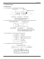
Troubleshooting
2. Troubleshooting
2.1 Display board
2.1.1 Icon explanation on indoor display board (Big cassette).
2.1.2 Icon explanation on indoor display board (Compact cassette & High static pressure Duct).
2.1.3 Icon explanation on indoor display board (Ceiling & Floor)
2.1.4 Icon explanation on indoor display board (A5 Duct)
PRE-DEF indicator(cooling and heating type)
or fan only indicator(cooling only type)
Timer indicator
Alarm indicator
Operation lamp
Infrared signal receiver
Display digital tube
Temporary button
MANUAL OPERATION TIMER DEF./FAN ALARM
Electrical Control
45
Troubleshooting
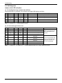
2.2. Self-diagnosis
,QGRRUXQLW¶V/('LQGLFDWLRQ
(1) For the Big Four-way cassette & the A5 Duct
During malfunction or protection, the indicators and digital LED displays as follow:
No
Operation
Timer
Def/Fan
Alarm
Digital LED Display
Malfunction or protection
1
ƿ
X
X
ƿ
E2
Indoor temperature sensor is abnormal
E3
Evaporator temperature sensor is abnormal
E4
Condenser temperature sensor is abnormal
EEPROM malfunction
X
X
X
ƿ
E7
5
X
X
ƿ
X
X
X
X
X
4
X
ƿ
X
ƿ
E8
Full-water malfunction
2
3
Note: ³X´ means off, ³ƿ´ means flashes at 5Hz
(2) For the other types indoor unit
No
Operation
Timer
Def/Fan
Alarm
Information
1
X
X
X
X
X
X
X
Ȗ
X
X
X
X
Normal standby
4
ƾ
X
Ȗ
ƿ
5
X
ƿ
X
X
6
ƿ
X
X
X
7
X
X
ƿ
X
8
ƿ
ƿ
9
X
X
X
X
X
ƿ
2
3
Normal off
Normal running
Forced cooling
Indoor temperature sensor is
abnormal
Evaporator temperature sensor is
abnormal
Condenser temperature sensor is
abnormal
Remark
Nothing wrong with the unit
when LED indicate these
contents.
Recover automatically after
errors are eliminated (For T3
PDOIXQFWLRQRI+3FDQ¶W
recover automatically)
EEPROM malfunction
Full-water malfunction
Note: ³Ȗ´ means on , ³X´ means off, ³ƿ´ means flashes at 5Hz, ³ƾ´ means flashes at 0.5Hz
46
Electrical Control
Troubleshooting
/('V¶IRUWKHLQGLFDWLRQRIRXWGRRUWURXEOH
Type
Contents
LED1
LED2
LED3
Trouble
Phase sequence
Flash
Off
Off
Trouble
Lack of phase(A,B)
Flash
Off
Off
Trouble
Lack of phase(C)
Off
Off
Off
Trouble
Protection of Low pressure
Flash
Flash
Off
Trouble
Overload of current
Off
Off
Flash
Trouble
Communication malfunction
Flash
Off
Flash
Trouble
Open-circuit and short-circuit trouble of T3
Off
Flash
Flash
Trouble
Open-circuit and short-circuit trouble of T4
Off
Flash
Off
Trouble
High temperature protection of condenser
Flash
Flash
Flash
Note:
1. If the LED1-LED3 are flashing slowly, means the system is stand-by.
2. T3: Outdoor condenser temperature sensor
3. T4: Outdoor ambient temperature sensor
Electrical Control
47
Troubleshooting
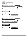
2.3. Solving steps for typical malfunction
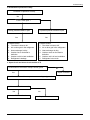
(1) For indoor unit
a. Indoor room temperature T1 and sensor evaporator temperature sensor T2 is abnormal
Is connection to connector of temp. sensor good?
No
Yes
Repair connector
Check the resistance of the temp. sensor according to Appendix 1
Is it the resistance is normal?
Yes
Indoor PCB is defective.
No
Replace the sensor
b. Condenser temperature sensor T3 is abnormal
Is connection to connector of temp. sensor good?
No
Yes
Repair connector
Check the resistance of the temp. sensor according to Appendix 1
Is it the resistance is normal?
Yes
Indoor PCB is defective.
48
No
Replace the sensor
Electrical Control
Troubleshooting
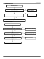
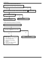
c. EEPROM malfunction
EEPROM malfunction
Yes
EEPROM chip is broken
Replace EEPROM
No
Yes
Replace the control chip
Check whether the main control chip is broken
No
Check PCB board or replace the main control board
f. Full-water malfunction
Full-water malfunction
No
Check whether the water-level switch is inserted well
Insert the water-level switch well
Yes
Yes
Check whether the water-level switch is broken
Replace the water-level switch
No
No
Check whether the water pump is normal
Replace the water pump
Yes
Check PCB board or replace the main control board
Electrical Control
49
Troubleshooting
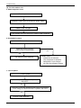
(2) For the outdoor unit
a. Phase sequence error:
Phase sequence error
Change the order of two of the wires to power supply.
Switch on the unit again.
If the problem cannot be solved, the outdoor PCB is defective
b. Overload of current
Overload of current
Check the current, normally
Is the current in rated range?
No
Yes
The outdoor PCB is defective
Possible reason
1. Outdoor fan is defective
2. The compressor is defective
3. Refrigerant is over charged
4. Air enter the refrigerant system
c. Lack of phase
Lack of phase
Check the power supply, is it 3 phase,
380-415V?
Yes
Check the connection between power supply and terminal,
is the voltage in outdoor terminal is 3 phase, 380-415V?
Yes
Outdoor PCB is defective
50
Electrical Control
Troubleshooting
d. Protection of pressure or temp.
Protection of pressure or temp.
Yes
Is it k1 or K2 open ?
Is temp. protective switch K1 open
Is pressure protective switch K2 open
Yes
Possible reason
1. The wires is loose to K1
2. Air or other gas in the refrigerant.
3. Heat exchanger is dirty
4. Outdoor fan or fan blade is
defective
5. Outdoor unit is in bad ventilation
6. Refrigerant is leakage
Yes
Possible reason
1. The wires is loose to K2
2. Air or other gas in the refrigerant.
3. Heat exchanger is dirty
4. Outdoor motor or fan blade is
defective
5. Outdoor unit is in bad ventilation
6. Refrigerant is too much
e. Open-circuit and short-circuit trouble of T3
Is connection to connector of temp. sensor good?
No
Repair connector
Yes
Check the resistance of the temp. sensor according to Appendix 1
Is it the resistance is normal?
Yes
Indoor PCB is defective.
Electrical Control
No
Replace the sensor
51
Troubleshooting
f. Open-circuit and short-circuit trouble of T4
Is connection to connector of temp. sensor good?
No
Yes
Check the resistance of the temp. sensor according to Appendix 1
Repair connector
Is it the resistance is normal?
No
Yes
Indoor PCB is defective.
Replace the sensor
g. High temperature protection of condenser
High temperature protection of condenser
Check the resistance of the temp. sensor
according to Appendix 1, is it normal?
Yes
Possible reason
1. Air or other gas in the refrigerant.
2. Heat exchanger is dirty
3. Outdoor fan or fan blade is
defective
4. Outdoor unit is bad ventilation
5. Refrigerant is leakage
52
No
Replace the sensor
Electrical Control
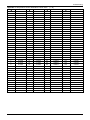
Troubleshooting
Appendix 1 Temperature Sensor Resistance Value Table (ć--K)
ć
-20
K Ohm
ć
20
K Ohm
12.6431
ć
60
K Ohm
2.35774
ć
100
K Ohm
0.62973
21
12.0561
61
2.27249
101
0.61148
-19
115.266
108.146
-18
101.517
22
11.5000
62
2.19073
102
0.59386
-17
96.3423
23
10.9731
63
2.11241
103
0.57683
-16
89.5865
24
10.4736
64
2.03732
104
0.56038
-15
84.2190
25
10.000
65
1.96532
105
0.54448
-14
79.3110
26
9.55074
66
1.89627
106
0.52912
-13
74.5360
27
9.12445
67
1.83003
107
0.51426
-12
70.1698
28
8.71983
68
1.76647
108
0.49989
-11
66.0898
29
8.33566
69
1.70547
109
0.48600
-10
62.2756
30
7.97078
70
1.64691
110
0.47256
-9
58.7079
31
7.62411
71
1.59068
111
0.45957
-8
56.3694
32
7.29464
72
1.53668
112
0.44699
-7
52.2438
33
6.98142
73
1.48481
113
0.43482
-6
49.3161
34
6.68355
74
1.43498
114
0.42304
-5
46.5725
35
6.40021
75
1.38703
115
0.41164
-4
44.0000
36
6.13059
76
1.34105
116
0.40060
-3
41.5878
37
5.87359
77
1.29078
117
0.38991
-2
39.8239
38
5.62961
78
1.25423
118
0.37956
-1
37.1988
39
5.39689
79
1.21330
119
0.36954
0
35.2024
40
5.17519
80
1.17393
120
0.35982
1
33.3269
41
4.96392
81
1.13604
121
0.35042
2
31.5635
42
4.76253
82
1.09958
122
0.3413
3
29.9058
43
4.57050
83
1.06448
123
0.33246
4
28.3459
44
4.38736
84
1.03069
124
0.32390
5
26.8778
45
4.21263
85
0.99815
125
0.31559
6
25.4954
46
4.04589
86
0.96681
126
0.30754
7
24.1932
47
3.88673
87
0.93662
127
0.29974
8
22.5662
48
3.73476
88
0.90753
128
0.29216
9
21.8094
49
3.58962
89
0.87950
129
0.28482
10
20.7184
50
3.45097
90
0.85248
130
0.27770
11
19.6891
51
3.31847
91
0.82643
131
0.27078
12
18.7177
52
3.19183
92
0.80132
132
0.26408
13
17.8005
53
3.07075
93
0.77709
133
0.25757
14
16.9341
54
2.95896
94
0.75373
134
0.25125
15
16.1156
55
2.84421
95
0.73119
135
0.24512
16
15.3418
56
2.73823
96
0.70944
136
0.23916
17
14.6181
57
2.63682
97
0.68844
137
0.23338
18
13.9180
58
2.53973
98
0.66818
138
0.22776
19
13.2631
59
2.44677
99
0.64862
139
0.22231
Electrical Control
53